1999 NISSAN PRIMERA turn signal
[x] Cancel search: turn signalPage 360 of 2267
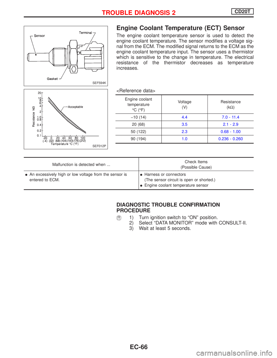
Engine Coolant Temperature (ECT) Sensor
The engine coolant temperature sensor is used to detect the
engine coolant temperature. The sensor modifies a voltage sig-
nal from the ECM. The modified signal returns to the ECM as the
engine coolant temperature input. The sensor uses a thermistor
which is sensitive to the change in temperature. The electrical
resistance of the thermistor decreases as temperature
increases.
Engine coolant
temperature
ÉC (ÉF)Voltage
(V)Resistance
(kW)
þ10 (14)4.4 7.0 - 11.4
20 (68)3.5 2.1 - 2.9
50 (122)2.3 0.68 - 1.00
90 (194)1.0 0.236 - 0.260
Malfunction is detected when ...Check Items
(Possible Cause)
lAn excessively high or low voltage from the sensor is
entered to ECM.lHarness or connectors
(The sensor circuit is open or shorted.)
lEngine coolant temperature sensor
DIAGNOSTIC TROUBLE CONFIRMATION
PROCEDURE
1) Turn ignition switch to ªONº position.
2) Select ªDATA MONITORº mode with CONSULT-II.
3) Wait at least 5 seconds.
SEF594K
SEF012P
TROUBLE DIAGNOSIS 2CD20T
EC-66
Page 367 of 2267
DIAGNOSTIC PROCEDURE
INSPECTION START
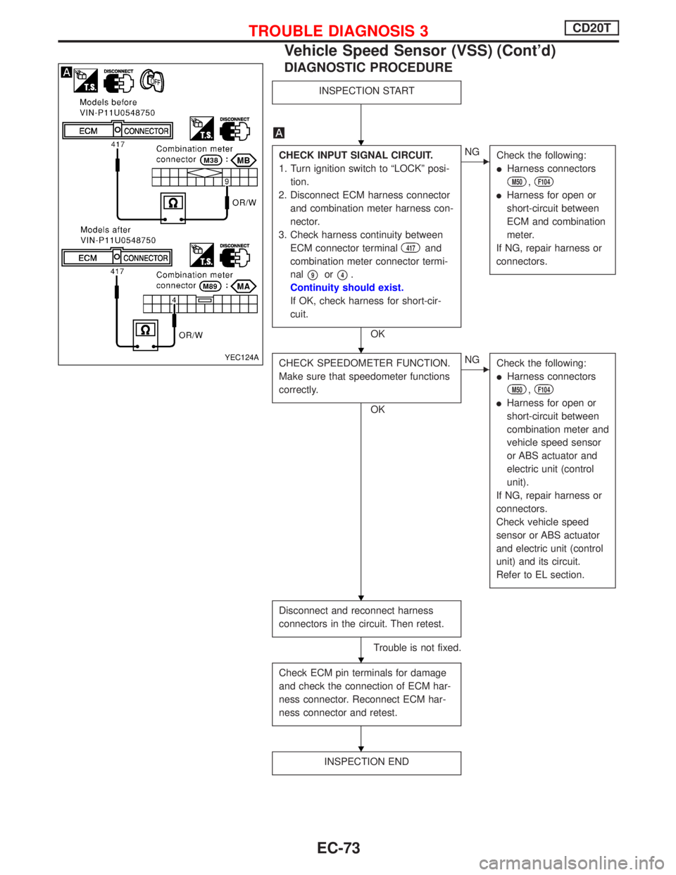
CHECK INPUT SIGNAL CIRCUIT.
1. Turn ignition switch to ªLOCKº posi-
tion.
2. Disconnect ECM harness connector
and combination meter harness con-
nector.
3. Check harness continuity between
ECM connector terminal
417and
combination meter connector termi-
nal
p9orp4.
Continuity should exist.
If OK, check harness for short-cir-
cuit.
OK
ENG
Check the following:
lHarness connectors
M50,F104
lHarness for open or
short-circuit between
ECM and combination
meter.
If NG, repair harness or
connectors.
CHECK SPEEDOMETER FUNCTION.
Make sure that speedometer functions
correctly.
OK
ENG
Check the following:
lHarness connectors
M50,F104
lHarness for open or
short-circuit between
combination meter and
vehicle speed sensor
or ABS actuator and
electric unit (control
unit).
If NG, repair harness or
connectors.
Check vehicle speed
sensor or ABS actuator
and electric unit (control
unit) and its circuit.
Refer to EL section.
Disconnect and reconnect harness
connectors in the circuit. Then retest.
Trouble is not fixed.
Check ECM pin terminals for damage
and check the connection of ECM har-
ness connector. Reconnect ECM har-
ness connector and retest.
INSPECTION END
YEC124A
H
H
H
H
H
TROUBLE DIAGNOSIS 3CD20T
Vehicle Speed Sensor (VSS) (Cont'd)
EC-73
Page 368 of 2267
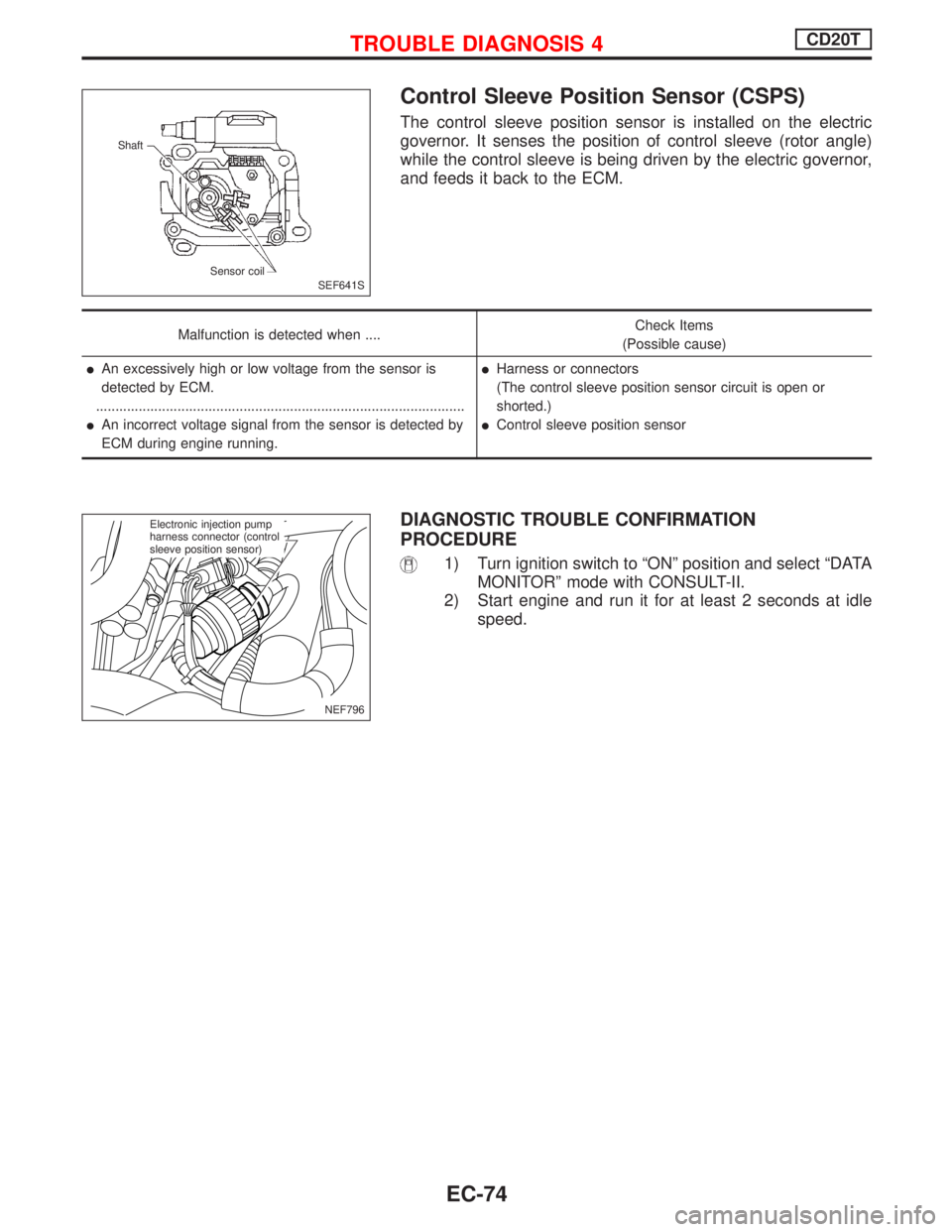
Control Sleeve Position Sensor (CSPS)
The control sleeve position sensor is installed on the electric
governor. It senses the position of control sleeve (rotor angle)
while the control sleeve is being driven by the electric governor,
and feeds it back to the ECM.
Malfunction is detected when ....Check Items
(Possible cause)
lAn excessively high or low voltage from the sensor is
detected by ECM.
...............................................................................................
lAn incorrect voltage signal from the sensor is detected by
ECM during engine running.
lHarness or connectors
(The control sleeve position sensor circuit is open or
shorted.)
lControl sleeve position sensor
DIAGNOSTIC TROUBLE CONFIRMATION
PROCEDURE
1) Turn ignition switch to ªONº position and select ªDATA
MONITORº mode with CONSULT-II.
2) Start engine and run it for at least 2 seconds at idle
speed.
SEF641S Shaft
Sensor coil
NEF796
.Electronic injection pump
harness connector (control
sleeve position sensor)
TROUBLE DIAGNOSIS 4CD20T
EC-74
Page 370 of 2267
DIAGNOSTIC PROCEDURE
INSPECTION START
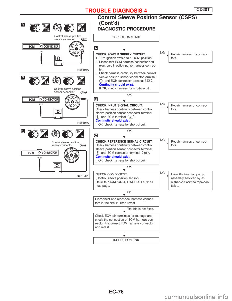
CHECK POWER SUPPLY CIRCUIT.
1. Turn ignition switch to ªLOCKº position.
2. Disconnect ECM harness connector and
electronic injection pump harness connec-
tor.
3. Check harness continuity between control
sleeve position sensor connector terminal
p3and ECM connector terminal320.
Continuity should exist.
If OK, check harness for short-circuit.
OK
ENG
Repair harness or connec-
tors.
CHECK INPUT SIGNAL CIRCUIT.
Check harness continuity between control
sleeve position sensor connector terminal
p2and ECM terminal321.
Continuity should exist.
If OK, check harness for short-circuit.
OK
ENG
Repair harness or connec-
tors.
CHECK REFERENCE SIGNAL CIRCUIT.
Check harness continuity between control
sleeve position sensor connector terminal
p1and ECM connector terminal322.
Continuity should exist.
If OK, check harness for short-circuit.
OK
ENG
Repair harness or connec-
tors.
CHECK COMPONENT
(Control sleeve position sensor).
Refer to ªCOMPONENT INSPECTIONº on
next page.
OK
ENG
Have the injection pump
assembly serviced by an
authorised service represen-
tative.
Disconnect and reconnect harness connec-
tors in the circuit. Then retest.
Trouble is not fixed.
Check ECM pin terminals for damage and
check the connection of ECM harness con-
nector. Reconnect ECM harness connector
and retest.
INSPECTION END
NEF196A
Control sleeve position
sensor connector
NEF197A
Control sleeve position
sensor connector
NEF198A
Control sleeve position
sensor connector
H
H
H
H
H
H
H
TROUBLE DIAGNOSIS 4CD20T
Control Sleeve Position Sensor (CSPS)
(Cont'd)
EC-76
Page 376 of 2267
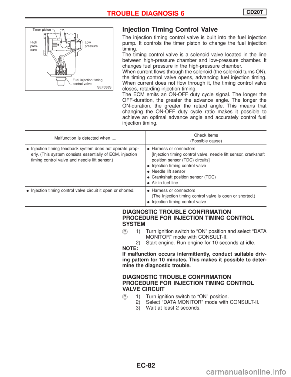
Injection Timing Control Valve
The injection timing control valve is built into the fuel injection
pump. It controls the timer piston to change the fuel injection
timing.
The timing control valve is a solenoid valve located in the line
between high-pressure chamber and low-pressure chamber. It
changes fuel pressure in the high-pressure chamber.
When current flows through the solenoid (the solenoid turns ON),
the timing control valve opens, advancing fuel injection timing.
When current does not flow through it, the timing control valve
closes, retarding injection timing.
The ECM emits an ON-OFF duty cycle signal. The longer the
OFF-duration, the greater the advance angle. The longer the
ON-duration, the greater the retard angle. This means that
changing the ON-OFF duty cycle ratio makes it possible to
achieve an optimal advance angle and accurately control fuel
injection timing.
Malfunction is detected when ....Check Items
(Possible cause)
lInjection timing feedback system does not operate prop-
erly. (This system consists essentially of ECM, injection
timing control valve and needle lift sensor.)lHarness or connectors
[Injection timing control valve, needle lift sensor, crankshaft
position sensor (TDC) circuits]
lInjection timing control valve
lNeedle lift sensor
lCrankshaft position sensor (TDC)
lAir in fuel line
lInjection timing control valve circuit it open or shorted.lHarness or connectors
(The Injection timing control valve is open or shorted.)
lInjection timing control valve
DIAGNOSTIC TROUBLE CONFIRMATION
PROCEDURE FOR INJECTION TIMING CONTROL
SYSTEM
1) Turn ignition switch to ªONº position and select ªDATA
MONITORº mode with CONSULT-II.
2) Start engine. Run engine for 10 seconds at idle.
NOTE:
If malfunction occurs intermittently, conduct suitable driv-
ing pattern for 10 minutes. This makes it possible to deter-
mine the diagnostic trouble.
DIAGNOSTIC TROUBLE CONFIRMATION
PROCEDURE FOR INJECTION TIMING CONTROL
VALVE CIRCUIT
1) Turn ignition switch to ªONº position.
2) Select ªDATA MONITORº mode with CONSULT-II.
3) Wait at least 2 seconds.
SEF638S Timer piston
High
pres-
sureLow
pressure
Fuel injection timing
control valve
TROUBLE DIAGNOSIS 6CD20T
EC-82
Page 378 of 2267
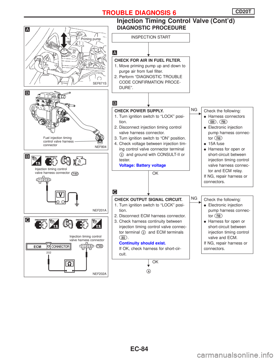
DIAGNOSTIC PROCEDURE
INSPECTION START
CHECK FOR AIR IN FUEL FILTER.
1. Move priming pump up and down to
purge air from fuel filter.
2. Perform ªDIAGNOSTIC TROUBLE
CODE CONFIRMATION PROCE-
DUREº.
CHECK POWER SUPPLY.
1. Turn ignition switch to ªLOCKº posi-
tion.
2. Disconnect injection timing control
valve harness connector.
3. Turn ignition switch to ªONº position.
4. Check voltage between injection tim-
ing control valve connector terminal
p3and ground with CONSULT-II or
tester.
Voltage: Battery voltage
OK
ENG
Check the following:
lHarness connectors
E89,F96
lElectronic injection
pump harness connec-
tor
F49
l15A fuse
lHarness for open or
short-circuit between
injection timing control
valve harness connec-
tor and ECM relay.
If NG, repair harness or
connectors.
CHECK OUTPUT SIGNAL CIRCUIT.
1. Turn ignition switch to ªLOCKº posi-
tion.
2. Disconnect ECM harness connector.
3. Check harness continuity between
injection timing control valve connec-
tor terminal
p2and ECM terminals
202.
Continuity should exist.
If OK, check harness for short-cir-
cuit.
OK
ENG
Check the following:
lElectronic injection
pump harness connec-
tor
F49
lHarness for open or
short-circuit between
injection timing control
valve and ECM.
If NG, repair harness or
connectors.
pA
SEF671S
Priming pump
NEF804
Fuel injection timing
control valve harness
connector
NEF201A
Injection timing control
valve harness connector
NEF202A
Injection timing control
valve harness connector
H
H
H
H
TROUBLE DIAGNOSIS 6CD20T
Injection Timing Control Valve (Cont'd)
EC-84
Page 380 of 2267
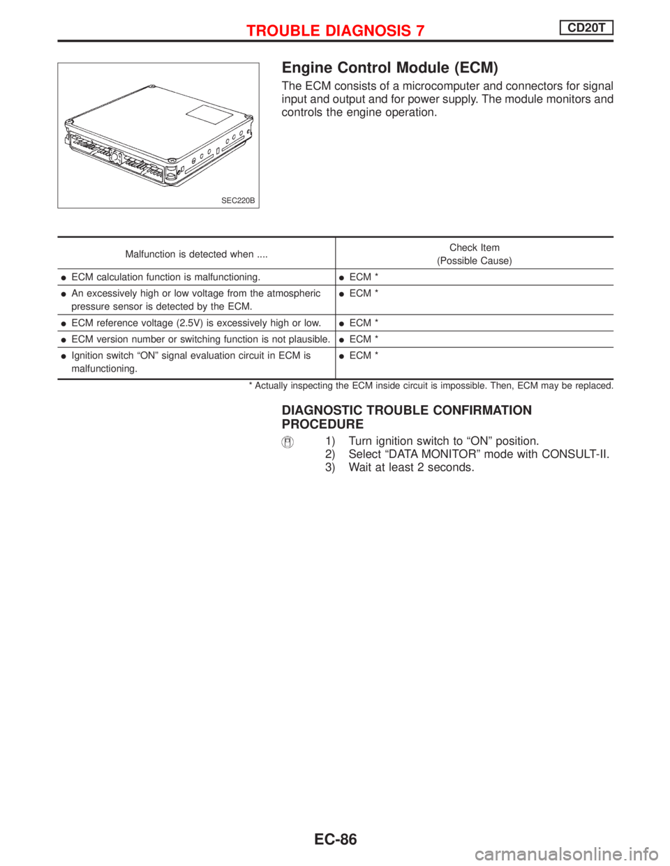
Engine Control Module (ECM)
The ECM consists of a microcomputer and connectors for signal
input and output and for power supply. The module monitors and
controls the engine operation.
Malfunction is detected when ....Check Item
(Possible Cause)
lECM calculation function is malfunctioning.lECM *
lAn excessively high or low voltage from the atmospheric
pressure sensor is detected by the ECM.lECM *
lECM reference voltage (2.5V) is excessively high or low.lECM *
lECM version number or switching function is not plausible.lECM *
lIgnition switch ªONº signal evaluation circuit in ECM is
malfunctioning.lECM *
* Actually inspecting the ECM inside circuit is impossible. Then, ECM may be replaced.
DIAGNOSTIC TROUBLE CONFIRMATION
PROCEDURE
1) Turn ignition switch to ªONº position.
2) Select ªDATA MONITORº mode with CONSULT-II.
3) Wait at least 2 seconds.
SEC220B
TROUBLE DIAGNOSIS 7CD20T
EC-86
Page 386 of 2267
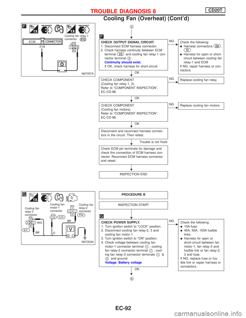
pC
CHECK OUTPUT SIGNAL CIRCUIT.
1. Disconnect ECM harness connector.
2. Check harness continuity between ECM
terminal
219and cooling fan relay-1 con-
nector terminal
p2.
Continuity should exist.
If OK, check harness for short-circuit.
OK
ENG
Check the following:
lHarness connectorsE43,F2
lHarness for open or short-
circuit between cooling fan
relay-1 and ECM
If NG, repair harness or con-
nectors.
CHECK COMPONENT
(Cooling fan relay-1, 2).
Refer to ªCOMPONENT INSPECTIONº,
EC-CD-96.
OK
ENG
Replace cooling fan relay.
CHECK COMPONENT
(Cooling fan motors).
Refer to ªCOMPONENT INSPECTIONº,
EC-CD-96.
OK
ENG
Replace cooling fan motors.
Disconnect and reconnect harness connec-
tors in the circuit. Then retest.
Trouble is not fixed.
Check ECM pin terminals for damage and
check the connection of ECM harness con-
nector. Reconnect ECM harness connector
and retest.
INSPECTION END
PROCEDURE B
INSPECTION START
CHECK POWER SUPPLY.
1. Turn ignition switch to ªLOCKº position.
2. Disconnect cooling fan relay-2, 3 and
cooling fan motor-1.
3. Turn ignition switch to ªONº position.
4. Check voltage between cooling fan
motor-1 connector terminal
p1; cooling
fan relay-2 connector terminal
p1; cool-
ing fan relay-3 connector terminals
p1&
p3and ground.
Voltage: Battery voltage
OK
ENG
Check the following:
l10A-fusel40A, 50A, 100A fusible
links
lHarness for open or
short-circuit between fan
motor-1, fan relay-3 and
fusible link or fan relay-2,
3 and fuse.
If NG, replace fuse or fus-
ible link or repair harness or
connectors.
pD
NEF207A
Cooling fan relay-1
connector
NEF203A
Cooling fan
relay-2
connector Cooling fan
motor-1
connector Cooling fan
relay-3
connector
H
H
H
H
H
H
H
H
TROUBLE DIAGNOSIS 8CD20T
Cooling Fan (Overheat) (Cont'd)
EC-92