1999 NISSAN PRIMERA turn signal
[x] Cancel search: turn signalPage 1815 of 2267

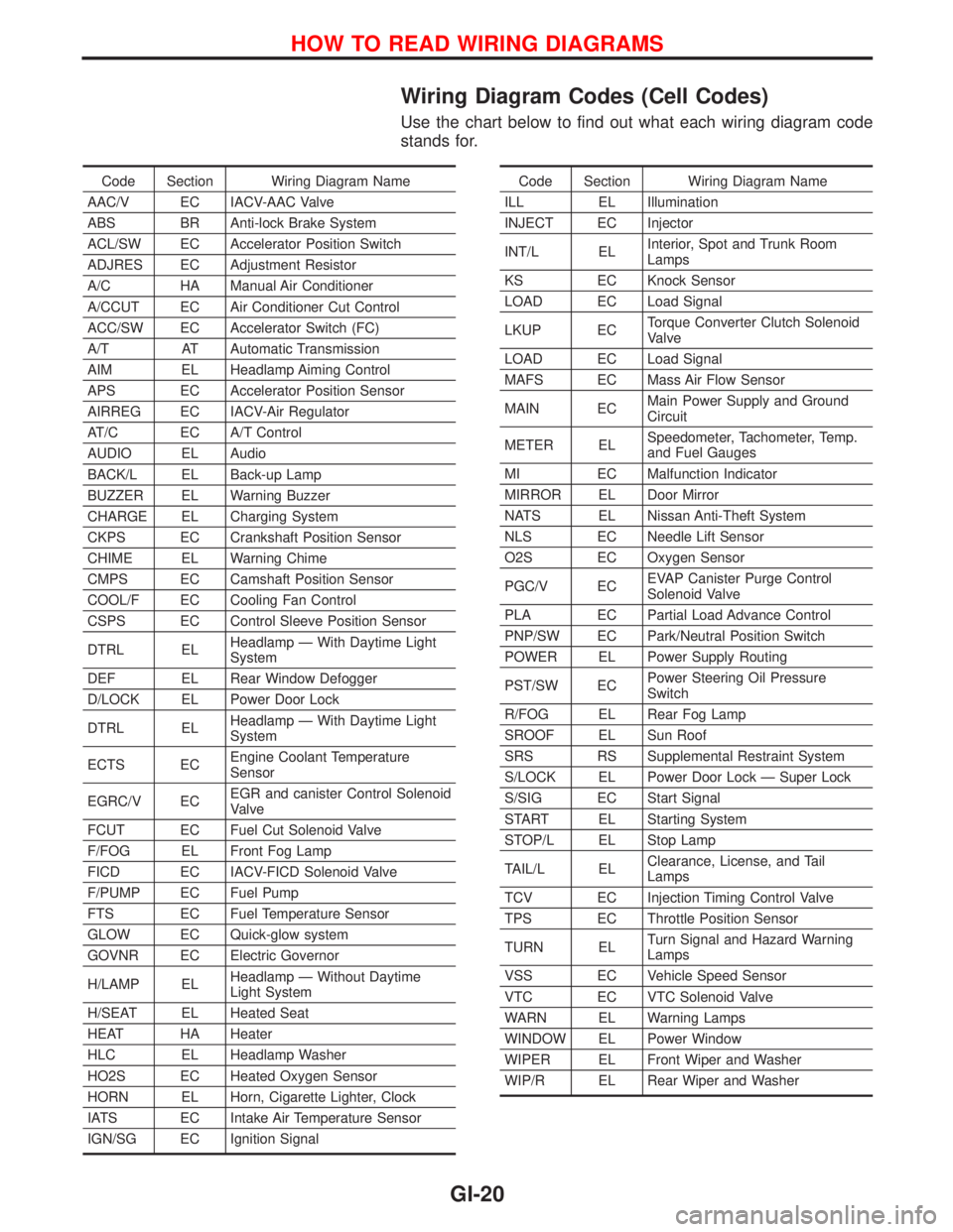
Wiring Diagram Codes (Cell Codes)
Use the chart below to find out what each wiring diagram code
stands for.
Code Section Wiring Diagram Name
AAC/V EC IACV-AAC Valve
ABS BR Anti-lock Brake System
ACL/SW EC Accelerator Position Switch
ADJRES EC Adjustment Resistor
A/C HA Manual Air Conditioner
A/CCUT EC Air Conditioner Cut Control
ACC/SW EC Accelerator Switch (FC)
A/T AT Automatic Transmission
AIM EL Headlamp Aiming Control
APS EC Accelerator Position Sensor
AIRREG EC IACV-Air Regulator
AT/C EC A/T Control
AUDIO EL Audio
BACK/L EL Back-up Lamp
BUZZER EL Warning Buzzer
CHARGE EL Charging System
CKPS EC Crankshaft Position Sensor
CHIME EL Warning Chime
CMPS EC Camshaft Position Sensor
COOL/F EC Cooling Fan Control
CSPS EC Control Sleeve Position Sensor
DTRL ELHeadlamp Ð With Daytime Light
System
DEF EL Rear Window Defogger
D/LOCK EL Power Door Lock
DTRL ELHeadlamp Ð With Daytime Light
System
ECTS ECEngine Coolant Temperature
Sensor
EGRC/V ECEGR and canister Control Solenoid
Valve
FCUT EC Fuel Cut Solenoid Valve
F/FOG EL Front Fog Lamp
FICD EC IACV-FICD Solenoid Valve
F/PUMP EC Fuel Pump
FTS EC Fuel Temperature Sensor
GLOW EC Quick-glow system
GOVNR EC Electric Governor
H/LAMP ELHeadlamp Ð Without Daytime
Light System
H/SEAT EL Heated Seat
HEAT HA Heater
HLC EL Headlamp Washer
HO2S EC Heated Oxygen Sensor
HORN EL Horn, Cigarette Lighter, Clock
IATS EC Intake Air Temperature Sensor
IGN/SG EC Ignition SignalCode Section Wiring Diagram Name
ILL EL Illumination
INJECT EC Injector
INT/L ELInterior, Spot and Trunk Room
Lamps
KS EC Knock Sensor
LOAD EC Load Signal
LKUP ECTorque Converter Clutch Solenoid
Valve
LOAD EC Load Signal
MAFS EC Mass Air Flow Sensor
MAIN ECMain Power Supply and Ground
Circuit
METER ELSpeedometer, Tachometer, Temp.
and Fuel Gauges
MI EC Malfunction Indicator
MIRROR EL Door Mirror
NATS EL Nissan Anti-Theft System
NLS EC Needle Lift Sensor
O2S EC Oxygen Sensor
PGC/V ECEVAP Canister Purge Control
Solenoid Valve
PLA EC Partial Load Advance Control
PNP/SW EC Park/Neutral Position Switch
POWER EL Power Supply Routing
PST/SW ECPower Steering Oil Pressure
Switch
R/FOG EL Rear Fog Lamp
SROOF EL Sun Roof
SRS RS Supplemental Restraint System
S/LOCK EL Power Door Lock Ð Super Lock
S/SIG EC Start Signal
START EL Starting System
STOP/L EL Stop Lamp
TAIL/L ELClearance, License, and Tail
Lamps
TCV EC Injection Timing Control Valve
TPS EC Throttle Position Sensor
TURN ELTurn Signal and Hazard Warning
Lamps
VSS EC Vehicle Speed Sensor
VTC EC VTC Solenoid Valve
WARN EL Warning Lamps
WINDOW EL Power Window
WIPER EL Front Wiper and Washer
WIP/R EL Rear Wiper and Washer
HOW TO READ WIRING DIAGRAMS
GI-20
Page 1945 of 2267

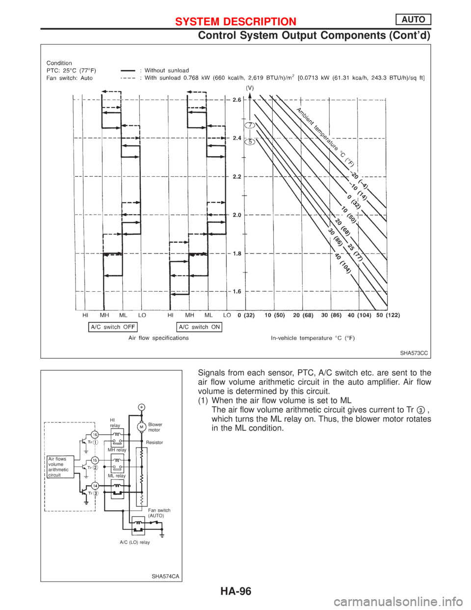
Signals from each sensor, PTC, A/C switch etc. are sent to the
air flow volume arithmetic circuit in the auto amplifier. Air flow
volume is determined by this circuit.
(1) When the air flow volume is set to ML
The air flow volume arithmetic circuit gives current to Tr
p3,
which turns the ML relay on. Thus, the blower motor rotates
in the ML condition.
SHA573CC
SHA574CA
Air flows
volume
arithmetic
circuitHI
relay
MH relay
ML relayBlower
motor
Resistor
Fan switch
(AUTO)
A/C (LO) relay
SYSTEM DESCRIPTIONAUTO
Control System Output Components (Cont'd)
HA-96
Page 1974 of 2267

S/SIG - Wiring diagram ....EC-QG-333, EC-SR-313,
EC-CD-145
Stabilizer bar (front) ........................................FA-32
Stall test (A/T) .................................................AT-34
Standardized relay ............................................EL-8
START - Wiring diagram .................................EL-37
Start signal .................EC-QG-38, 332, EC-SR-312,
EC-CD-145
Starter .......................................................EL-37, 43
Starting system ...............................................EL-37
Steering gear and linkage inspection ............MA-53
Steering knuckle........................................FA-11, 12
Stop lamp ......................................................EL-104
STOP/L - Wiring diagram..............................EL-104
Sun roof, electric ...........................................EL-230
Sunload sensor ..............................................HA-86
Sunroof .....................................................BT-31, 46
Super lock .............................................EL-245, 265
Supplemental Restraint System .......................RS-8
Supplemental restraint system - Wiring
diagram .......................................................RS-33
Symbols and abbreviations .............................GI-38
Symptom matrix chart ...........EC-QG-82, EC-SR-94
Synchronizer (M/T) ......................MT-22, 27, 59, 65
System readiness test (SRT) code ..........EC-SR-50
T
Tachometer ...........................................EL-141, 146
Tail lamp ........................................................EL-100
TCM circuit diagram ........................................AT-10
TCM inspection table ......................................AT-41
Temperature control cable and linkage
adjustment ..................................................HA-83
THEFT - Wiring diagram ...............................EL-316
Theft warning system ....................................EL-311
Thermal protector .........................................HA-113
Thermo control amp .......................................HA-80
Thermostat ..........................................LC-11, 23, 34
Third link (front susp.) .....................................FA-29
Three way catalyst ............EC-QG-258, EC-SR-246
Three way catalyst precautions.........................GI-6
Throttle position sensor
(TPS) .............................EC-QG-125, EC-SR-137
Throttle position sensor
adjustment .........................EC-QG-72, EC-SR-84
Throttle position switch ...............EC-SR-271, AT-85
Tightening torque of standard bolts.................GI-50
Time control system ......................................EL-306
Timing belt....................................................EM-131
Timing chain.............................................EM-19, 75
Tire rotation ....................................................MA-53
Tire size ...........................................................GI-45
Torque converter installation .........................AT-117
Torque convertor clutch solenoid valve...........AT-69
Tow truck towing ..............................................GI-46
Towing point.....................................................GI-49
TP/SW - Wiring diagram ........................EC-SR-273
TPS - Wiring diagram .......EC-QG-128, EC-SR-140
Transmission case (M/T) ................................MT-39Transverse link (front) .....................................FA-32
Trim .................................................................BT-18
Triple pressure switch ....................................HA-79
Trouble diagnoses ...........................................GI-35
Trunk lid ............................................................BT-7
Trunk lid opener - See Trunk lid .......................BT-7
Trunk room lamp...................................EL-130, 131
Trunk room trim...............................................BT-28
Turbocharger........................................EM-156, 201
Turbocharger precautions..................................GI-6
TURN - Wiring diagram.................................EL-118
Turn signal lamp............................................EL-117
Two trip detection logic .........EC-QG-36, EC-SR-48
U
Upper link (front susp.) ...................................FA-29
V
Vacuum hose (brake system).........................BR-20
Vacuum hose drawing (Engine
control) ............EC-QG-19, EC-SR-21, EC-CD-13
Valve clearance .............................EM-40, 179, 191
Valve guide..............EM-36, 93, 142, 180, 189, 197
Valve lifter ..............................EM-40, 145, 179, 198
Valve seat................EM-38, 95, 143, 182, 190, 198
Valve spring.............EM-39, 96, 145, 179, 189, 197
Vehicle identification number...........................GI-43
Vehicle speed sensor
(VSS) ..........EC-QG-267, EC-SR-255, EC-CD-70
Viscosity number (SAE) .................................MA-17
VSS - Wiring
diagram .......EC-QG-269, EC-SR-257, EC-CD-71
W
WARN - Wiring diagram ...............................EL-167
Warning buzzer .............................................EL-180
Warning chime ..............................................EL-180
Warning lamps ..............................................EL-165
Washer, front .................................................EL-186
Washer, rear..................................................EL-193
Water cock control rod adjustment ................HA-82
Water pump ........................................LC-10, 22, 33
Water temperature gauge .....................EL-141, 146
Weatherstrip - See Exterior ............................BT-31
Wheel alignment (front) ..................................FA-35
Wheel alignment (rear).....................................RA-6
Wheel balance ...............................................MA-53
Wheel bearing (front axle) ....................FA-6, 12, 35
Wheel bearing (rear) ........................................RA-5
Wheel hub (front) ............................................FA-12
Wheel hub (rear) ..............................................RA-7
Wheel sensors (ABS) .....................................BR-53
Wheel size .......................................................GI-45
Wheelbase (Dimensions) ................................GI-45
ALPHABETICAL INDEX
IDX-7
Page 2022 of 2267

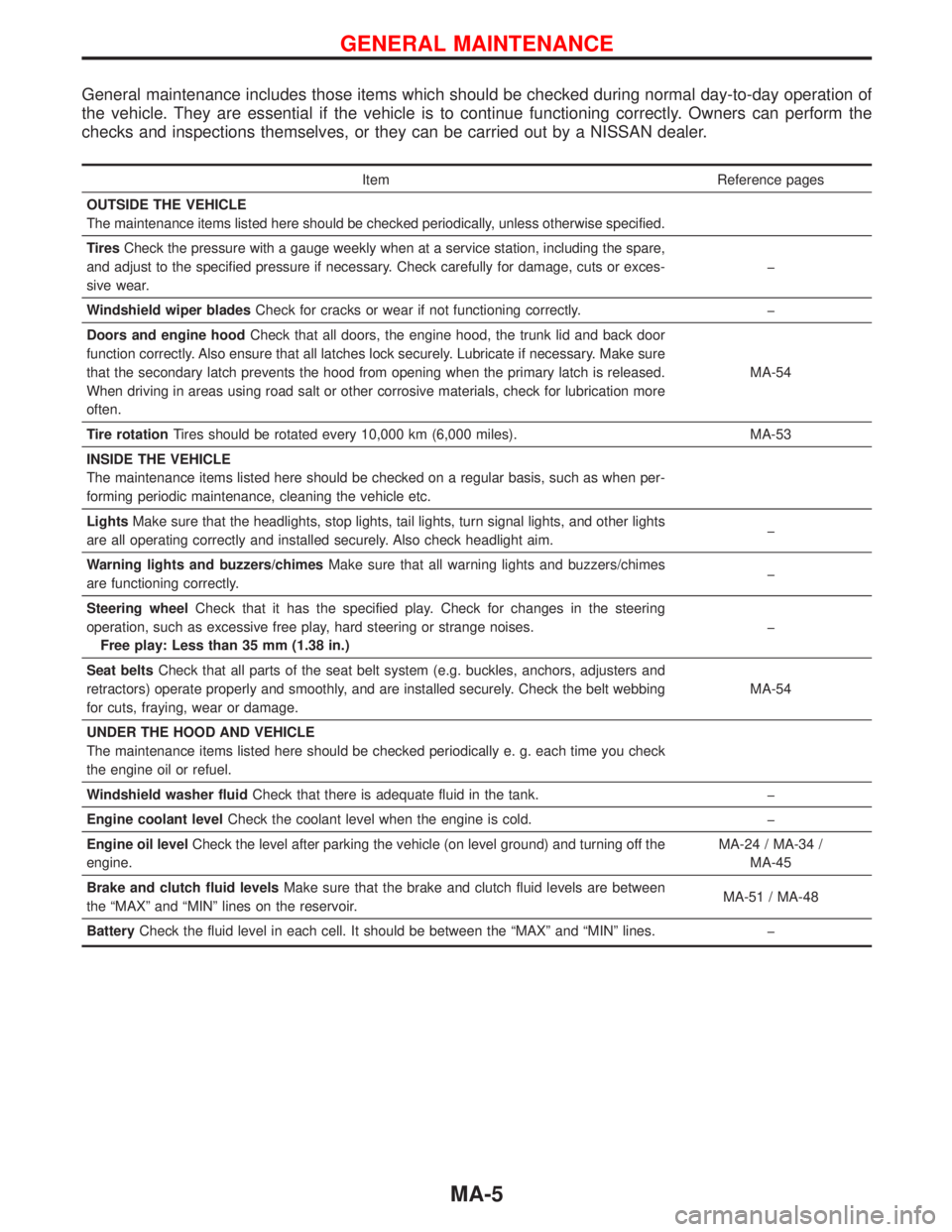
General maintenance includes those items which should be checked during normal day-to-day operation of
the vehicle. They are essential if the vehicle is to continue functioning correctly. Owners can perform the
checks and inspections themselves, or they can be carried out by a NISSAN dealer.
Item Reference pages
OUTSIDE THE VEHICLE
The maintenance items listed here should be checked periodically, unless otherwise specified.
TiresCheck the pressure with a gauge weekly when at a service station, including the spare,
and adjust to the specified pressure if necessary. Check carefully for damage, cuts or exces-
sive wear.�
Windshield wiper bladesCheck for cracks or wear if not functioning correctly.�
Doors and engine hoodCheck that all doors, the engine hood, the trunk lid and back door
function correctly. Also ensure that all latches lock securely. Lubricate if necessary. Make sure
that the secondary latch prevents the hood from opening when the primary latch is released.
When driving in areas using road salt or other corrosive materials, check for lubrication more
often.MA-54
Tire rotationTires should be rotated every 10,000 km (6,000 miles). MA-53
INSIDE THE VEHICLE
The maintenance items listed here should be checked on a regular basis, such as when per-
forming periodic maintenance, cleaning the vehicle etc.
LightsMake sure that the headlights, stop lights, tail lights, turn signal lights, and other lights
are all operating correctly and installed securely. Also check headlight aim.�
Warning lights and buzzers/chimesMake sure that all warning lights and buzzers/chimes
are functioning correctly.�
Steering wheelCheck that it has the specified play. Check for changes in the steering
operation, such as excessive free play, hard steering or strange noises.
Free play: Less than 35 mm (1.38 in.)�
Seat beltsCheck that all parts of the seat belt system (e.g. buckles, anchors, adjusters and
retractors) operate properly and smoothly, and are installed securely. Check the belt webbing
for cuts, fraying, wear or damage.MA-54
UNDER THE HOOD AND VEHICLE
The maintenance items listed here should be checked periodically e. g. each time you check
the engine oil or refuel.
Windshield washer fluidCheck that there is adequate fluid in the tank.�
Engine coolant levelCheck the coolant level when the engine is cold.�
Engine oil levelCheck the level after parking the vehicle (on level ground) and turning off the
engine.MA-24 / MA-34 /
MA-45
Brake and clutch fluid levelsMake sure that the brake and clutch fluid levels are between
the“MAX”and“MIN”lines on the reservoir.MA-51 / MA-48
BatteryCheck the fluid level in each cell. It should be between the“MAX”and“MIN”lines.�
GENERAL MAINTENANCE
MA-5