Page 1151 of 1701
ENGINECOOLING SYSTEM
IiJ
6.28 -8.34 (0.641 -0.851, 55.6-73.8)
SEC.
210 Water
Pump
~ 6.28 -8.34 (0.641 -0.851, 55.6-73.8)
WaterpumppUlley
l
~Liquid gasket
~ N.m(kg-m, in-Ib)
SLC989AB
•
CAUTION:
• When removing waterpumpassembly, becareful nottoget
coolant ontiming chain.
• Water pumpcannot bedisassembled andshould be
replaced asaunit.
• After installing waterpump, connect hoseandclamp
securely, thencheck forleaks using radiator captester.
REMOVAL
1. Drain coolant fromradiator andcylinder block.
2. Remove drivebeltsforcompressor, powersteering pump
and alternator.
3. Remove waterpumppulley.
4. Remove waterpump.
INSPECTION
1. Check bodyassembly forrust orcorrosion.
2. Check forrough operation duetoexcessive endplay.
SLC162A LC-13
Page 1199 of 1701

TIMINGCHAIN
Without
VTC
CAUTION:
• After removing timingchain,donot turn crankshaft and
camshaft separately, orvalves willstrike piston heads.
• When installing camshafts, chaintensioner, oilseals, or
other sliding parts,lubricate contacting surfaceswithnew
engine oil.
• Apply newengine oiltobolt threads andseat surfaces when
installing cylinderhead,camshaft sprocket,crankshaft
pulley, andcamshaft brackets.
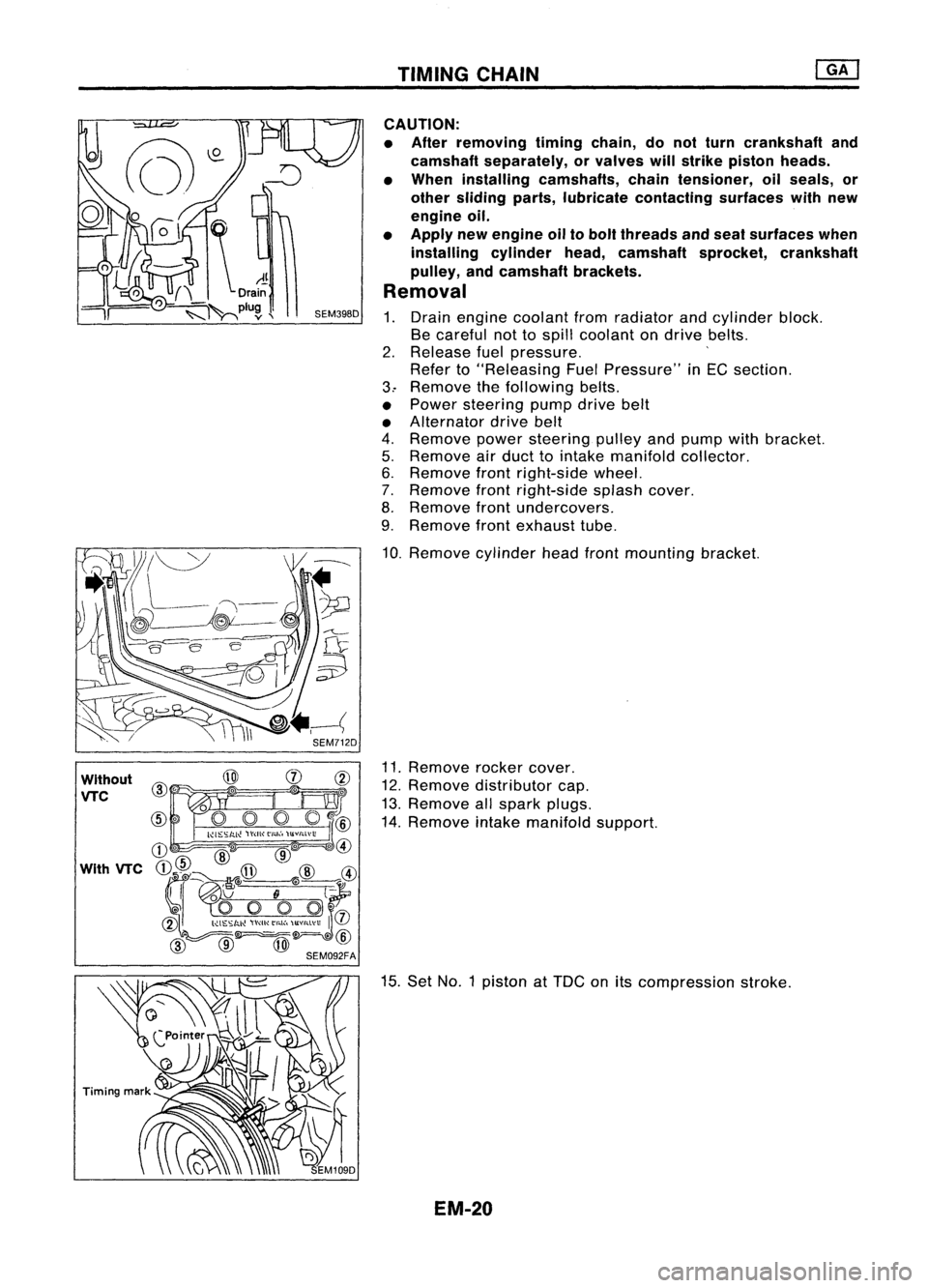
Removal
1. Drain engine coolant fromradiator andcylinder block.
Be careful nottospill coolant ondrive belts.
2. Release fuelpressure. '
Refer to"Releasing FuelPressure" inEG section.
3.. Remove thefollowing belts.
• Power steering pumpdrivebelt
• Alternator drivebelt
4. Remove powersteering pulleyandpump withbracket.
5. Remove airduct tointake manifold collector.
6. Remove frontright-side wheel.
7. Remove frontright-side splashcover.
8. Remove frontundercovers.
9. Remove frontexhaust tube.
10. Remove cylinderheadfrontmounting bracket.
11. Remove rockercover.
12. Remove distributor cap.
13. Remove allspark plugs.
14. Remove intakemanifold support.
15. Set NO.1 piston at
TOG
onitscompression stroke.
EM-20
Page 1201 of 1701
Slackside
chain gUide SEM081FTIMING
CHAIN
Removal (Coni'd)
35. Remove enginefrontmounting.
36. Remove enginefrontmounting bracket.
37. Remove frontcover boltsandfront cover asshown.
*1:
Located onengine frontmounting bracket
*2: Located onwater pump
*3: Located onpower steering pumpadjusting bar
38. Remove idlersprocket.
39. Remove lowertiming chain.
40. Remove oilpump drivespacer.
41. Remove chainguides.
42. Remove crankshaft sprocket.
EM-22
Page 1208 of 1701

WithoutVTC
Engine front
Unit: mm(in)
~(0.39)
~1-J--10 (0.39)
* -\
3 (0.12)
Z~
Liquid
gasket
SEM59BEA TIMING
CHAIN
Installation (Cont'd)
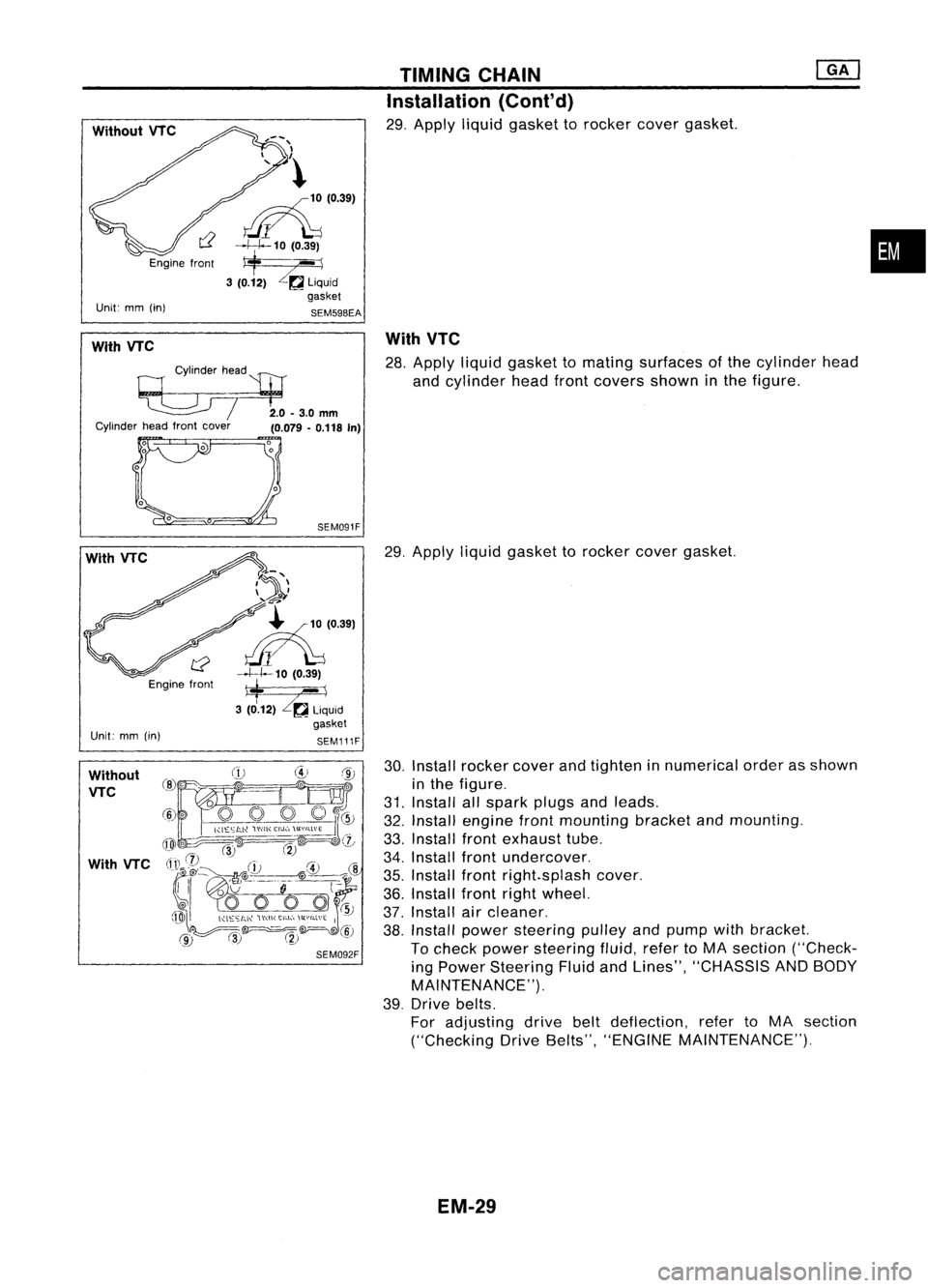
29. Apply liquidgasket torocker covergasket.
•
With VTC
Cylinderhead
'l:tJ
~ /2.0-3.0mm
Cylinder headfront cover
(0.079-0.118 In)
With
VTC
28. Apply liquidgasket tomating surfaces ofthe cylinder head
and cylinder headfrontcovers showninthe figure.
With VTC
Engine front
Unit: mm(in)
SEM091F
7~'\
\ ..... -4'
~-'?
~'0391
~10 (0.39)
*
--1
3 (0.12)
Zr.a
liquid
gasket
SEM111F
29.
Apply liquidgasket torocker covergasket.
Without VTC
With VTC
30.
Install rocker coverandtighten innumerical orderasshown
in the figure.
31. Install allspark plugsandleads.
32. Install engine frontmounting bracketandmounting.
33. Install frontexhaust tube.
34. Install frontundercover.
35. Install frontright.splash cover.
36. Install frontrightwheel.
37. Install aircleaner.
38. Install power steering pulleyandpump withbracket.
To check power steering fluid,refertoMA section ("Check-
ing Power Steering FluidandLines", "CHASSIS ANDBODY
MAINTENANCE").
39. Drive belts.
For adjusting drivebeltdeflection, refertoMA section
("Checking DriveBelts", "ENGINE MAINTENANCE").
EM-29
Page 1209 of 1701
OILSEAL REPLACEMENT
KV10l07902
VALVE
OilSEAL
1. Remove rockercover.
2. Remove camshaft.
3. Remove valvespring. Referto"CYLINDER HEAD".
4. Remove valveoilseal withasuitable tool.
Piston concerned shouldbeset atTOC toprevent valvefrom
falling.
5. Apply engine oiltonew valve oilseal andinstall itwith Tool.
SEM136D
10.5
mm
(0.413 In)
SEM137D
FRONTOilSEAL
1. Remove thefollowing parts:
• Engine undercover
• Right-side splashcover
• Alternator andpower steering drivebelts
• Crankshaft pulley
2. Remove frontoilseal from front cover.
Be careful nottodamage oilseal portion.
• Install newoilseal inthe direction shown.
Engine /',
inside
Y
~
Engine
Youtside
Oil seal lip Dust
seal
lip
SEM715A EM-30
Page 1224 of 1701

ENGINEREMOVAL
WARNING:
a. Situate vehicle onaflat and solid surface.
b. Place chocks atfront andback ofrear wheels.
c. Donot remove engineuntilexhaust systemhascompletely
cooled off.
Otherwise, youmay burn yourself and/orfiremay break out
in fuel line.
d. For safety during subsequent steps,thetension ofwires
should beslackened againsttheengine.
e. Before disconnecting fuelhose, release fuelpressure from
fuel line.
Refer to"Releasing FuelPressure" inEC section.
f. Besure tohoist engine andtransaxle inasafe manner.
g. For engines notequipped withengine slingers, attach
proper slingers andbolts described inPARTS CATALOG.
CAUTION:
• When liftingengine, besure toclear surrounding parts.
Take special careforaccelerator wirecasing, brakelines
and brake master cylinder.
• Inhoisting theengine, alwaysuseengine slingers inasafe
manner.
• Inremoving driveshaft, becareful nottodamage grease
seal oftransaxle.
Engine cannotberemoved separately fromtransaxle. Remove
engine withtransaxle.
Removal
1. Drain water.
2. Remove hood.
3. Remove battery.
4. Remove reservoir tankandbracket.
5. Remove drivebelts.
6. Remove alternator, compressor andpower steering oil
pump fromengine.
Power steering pumpdoesnotneed tobe disconnected from
power steering tubes.
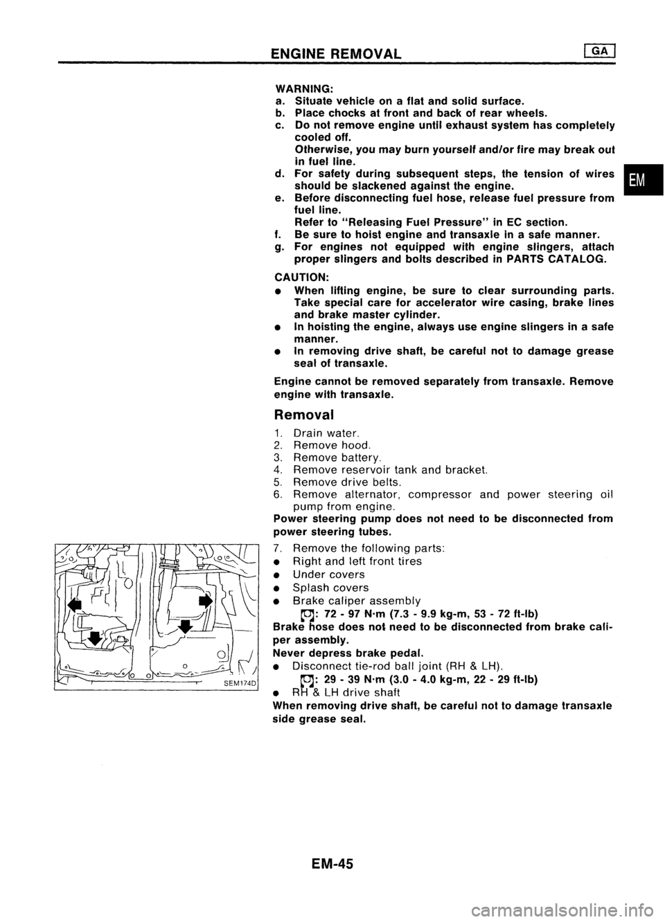
7. Remove thefollowing parts:
• Right andleftfront tires
• Under covers
• Splash covers
• Brake caliper assembly
~: 72-97 N'm (7.3•9.9 kg-m, 53•72 ft-Ib)
Brake hosedoes notneed tobe disconnected frombrake cali-
per assembly.
Never depress brakepedal.
• Disconnect tie-rodballjoint (RH
&
LH).
~: 29-39 N'm (3.0-4.0 kg-m, 22-29 ft-Ib)
• RH
&
LH drive shaft
When removing driveshaft, becareful nottodamage transaxle
side grease seal.
EM-45
•
Page 1238 of 1701

OUTERCOMPONENT PARTS
•
SEM231F
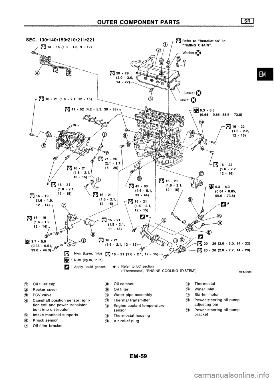
SEC.
130-140-150-210-211-221
~ __to:J
13•16 (1.3 -1.6, 9.12)
to:J
16•21 (1.6. 2.1,12. 15)
to:J
20•29
(2.0 •3.0,
14 .22)
to:J
41-52 (4.2 -5.3, 30-38)
~---- D_?
. 'J ~
~~~ 0
-t::;-.....~ /,
0
to:J
21-26 ./"
(2.1. 2.7, ,./"~/'
12 -1~)
fs\
19-~~7
~ to:J
16•21
Q
to:J
18. 21 ,
to:J
45_60 (1.6-2.1, 0
Ii]
6.3 _8.3
(1.8 •2.1, (4.6•6.1, 12•15)
1
(0.64•0.85,
to:J
16•19 13-15)
to:J
16•21 33•44)
(1.6 -1.9, (1.6-2.1,
to:J
16•21
12 -14)
12•15)
t"J
16•,.
f"-~
t"J
15•21
r::!
*
H
...----4lJ
~~'. '1~
J
r \~ ~~'..,:;
1,
~Q.
/¥i-;:
--'Il
1il3.7 -5.0
J~
--A)
to:J
16-21
~11V>/
(0.38 _0.51, A~ - (1.6.2.1,12•15)\...,//
~to:J
20.29(2.0-3.0, 14-22)
33.0 •44.3)
Y
&'/-
:f~l
to:J
20•26 (2.0 •2.7, 14-20)
to:J :
N'm (kg-m, fl-Ib)
to:J
16-21 (1.6 -2.1, 12-15)~/
Ii] :
N'm (kg-m, in-Ib) •
~ :Apply
liquidgasket.
*:
Refer toLC section
("Thermostat", "ENGINECOOLING SYSTEM").
G)
Oilfiller cap
@
Oilcatcher
@
Thermostat
@
Rocker cover
@
Oilfilter
@
Water inlet
@
PCVvalve
@
Water pipeassembly
@
Starter motor
@
Camshaft
positionsensor,igni-
@
Thermal transmitter
@
Power steering oilpump
tion coiland power transistor
@
Engine coolant temperature adjusting
bar
built intodistributor
sensor
@
Power
steering oilpump
@
Intake manifold supports
@
Thermostat housing bracket
@
Knock sensor
@
Airrelief plug
rJ)
Oilfilter bracket
EM-59
Page 1248 of 1701
TIMINGCHAIN
CAUTION:
• After removing timingchain,donot turn crankshaft and
camshaft separately, orvalves willstrike piston heads.
• When installing rockerarms,camshafts, chaintensioner, oil
seals, orother sliding parts,lubricate contacting surfaces
with newengine oil.
• Apply newengine oiltobolt threads andseat surfaces when•
installing cylinderhead,camshaft sprockets, crankshaft
pulley, andcamshaft brackets.
Removal
1. Release fuelpressure.
Refer to"Releasing FuelPressure" inEC section.
2. Remove engineundercovers.
3. Remove frontRHwheel andengine sidecover.
4. Drain coolant byremoving cylinderblockdrainplugand
radiator draincock.
5. Remove radiator.
6. Remove airduct tointake manifold.
7. Remove drivebeltsandwater pumppulley.
8. Remove alternator andpower steering oilpump.
9. Remove vacuumhoses,fuelhoses, wires,harness, connec-
tors andsoon.
10. Remove allspark plugs.
11. Remove rockercoverandoilseparator.
12. Remove intakemanifold supports.
EM-69