1995 NISSAN ALMERA N15 steering
[x] Cancel search: steeringPage 1539 of 1701
SERVICEDATAANDSPECIFICATIONS (SOS)
Engine Maintenance
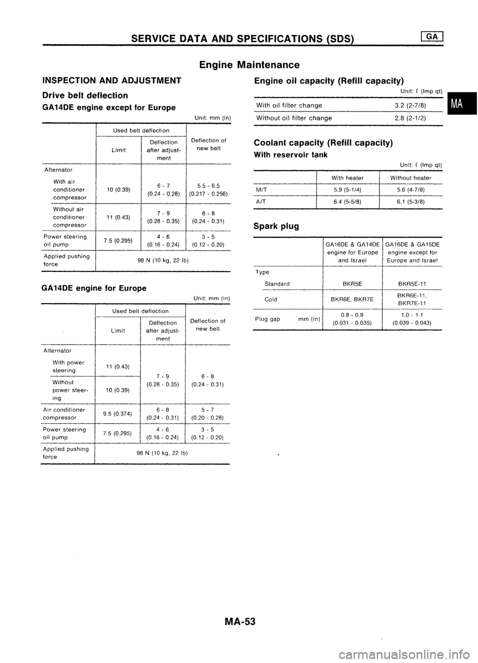
Engine oilcapacity (Refillcapacity)
Unit:
r
(Imp qt)
INSPECTION
ANDADJUSTMENT
Drive beltdeflection
GA14DE engineexceptforEurope
Unit:mm(in)
With
oilfilter change
Without oilfilter change
3.2
(2-7/8)
2.8
(2-1/2)
•
Used beltdeflection
Deflection Deflection
of
Limit afteradjust- new
belt
ment
Alternator With air
6-7 55-6.5
conditioner 10(0.39)
(0.24-0.28)
(0.217-0.256)
compressor
Without air
7-9 6-8
conditioner 11(0.43)
(0.28-0.35) (0.24-0.31)
compressor
Power steering
7.5(0.295) 4
-6
3-5
oil pump
(0.16-0.24) (0.12-0.20)
Applied pushing
98N(10 kg, 22Ib)
force
GA14DE engineforEurope
Unit:mm(in)
Used beltdeflection
Deflection Deflection
of
Limit afteradjust- new
belt
ment
Alternator
With power
11(0.43)
steering
7-9
6-8
Without (0.28-0.35) (0.24-0.31)
power steer- 10(0.39)
ing
Air conditioner
9.5(0.374) 6
-8 5
-7
compressor (0.24
-0.31) (0.20-0.28)
Power steering
75(0.295) 4
-6 3-5
oil pump (0.16
-0.24)
(0.12-0.20)
Applied pushing
98N(10 kg,22Ib)
force
Coolant
capacity (Refillcapacity)
With reservoir tank
Unit:((Imp qt)
With heater Without
heater
M/T
5.9(5-1/4) 5.6(4-7/8)
A/T 6.4(5-5/8) 6.1(5-3/8)
Spark plug
GA16DE
&
GA14DE
GA16DE
&
GA15DE
engine forEurope engineexceptfor
and Israel EuropeandIsrael
Type Standard BKR5EBKR5E-11
Cold BKR6E,
BKR7E BKR6E-11,
BKR7E-11
Plug gap mm
(in) 0.8
-0.9 1.0
-
1.1
(0.031 -0.035) (0.039-0.043)
MA-53
Page 1540 of 1701

SERVICEDATAANDSPECIFICATIONS (SOS)
INSPECTION ANDADJUSTMENT
Drive beltdeflection Engine
Maintenance
Engine oilcapacity (Refillcapacity)
Unit:
f
(Imp qt)
Unit:
f
(Imp qt)
Spark plug(Platinum-tipped type)
Coolant
capacity (Refillcapacity)
With reservoir tank
Withheater Withoutheater
MIT
6.1(5-3/8)
5.8(5-1/8)
AIT
6.6(5-718) 6.3(5-1/2)
Reservoir tank
07(5/8)
3.4
(3)
3.2 (2-7/8)
With
oilfilter change
Without oilfilter change
Unit:
mm(in)
Used beltdeflection
Deflection Deflection
of
Limit afteradjust- new
belt
ment
Alternator With aircon-
11.5-12.5 7-8 6.5-7.5
ditioner com-
(0.453-0.492) (0.28
-0.31) (0.256-0.295)
pressor
Without air
12-13 8-9 7-8
conditioner
(0.47-0.51) (0.31-0.35) (0.28-0.31)
compressor
Power steering 6-7 4-5 3.5-4.5
oil pump (0.24-0.28) (0.16-0.20) (0.138-0.177)
Applied pushing
98N(10 kg,22Ib)
force
Make
Type
Standard
Alternative NGK
PFR58-11
PFR68-11 PFR78-11
MA-54
Page 1541 of 1701
SERVICEDATAANDSPECIFICATIONS (50S)
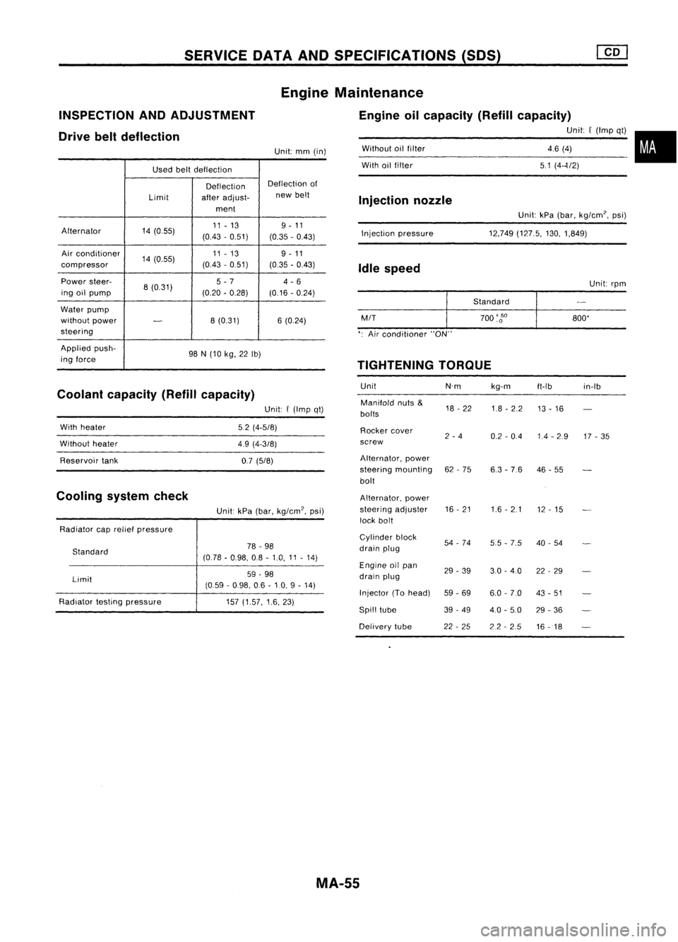
Used beltdeflection
Deflection Deflection
of
Limit afteradjust- new
belt
ment
Alternator 14(055) 11
-13 9-11
(0.43 -0.51)
(0.35-0.43)
Air conditioner
14(0.55) 11
-13
9-11
compressor (0.43
-0.51)
(0.35-0.43)
Power steer-
8(0.31) 5
-7
4-6
ing oilpump (0.20-0.28)
(0.16-0.24)
Water pump
without power
-
8
(0.31) 6(0.24)
steering
Applied push-
98N(10 kg, 22Ib)
ing force
Coolant capacity (Refillcapacity)
INSPECTION
ANDADJUSTMENT
Drive beltdeflection
Unit:kPa(bar, kg/cm', psi)
12,749 (127.5, 130,1,849)
Without
oilfilter
With oilfilter
Injection pressure
Injection
nozzle
Idle speed
Unit:rpm
Standard
M/T
700
'go
800'
': Air conditioner "ON"
TIGHTENING TORQUE
Unit N'mkg-m
ft-Ib in-Ib
Manifold nuts
&
18-22
1.8-2.2
bolts 13
-16
Rocker cover
2-4
0.2-0.4 1.4-2.9 17-35
screw
Alternator, power
steering mounting 62-75
6.3-76 46
-55
bolt
Alternator, power
steering adjuster 16
-21
1.6-2.1
12-15
lock bolt
Cylinder block
54-74
5.5-7.5 40
-54
drain plug
Engine oilpan
29-39 3.0-4.0 22-29
drain plug
Injector (Tohead)
59-69 6.0-7.0 43-51
Spill tube 39-49
4.0-5.0 29-36
Delivery tube 22-25 2.2-2.5
16-18
Engine
Maintenance
Engine oilcapacity (Refillcapacity)
Unit:[(Imp qt)•
46 (4)
51 (4--1/2)
Unit:
mm(in)
Unit:
f
(Imp qt)
5.2 (4-5/8)
49 (4-3/8)
0.7 (5/8)
Unit: kPa(bar, kg/cm', psi)
78 -98
(0.78 -0.98, 08-1.0, 11-14)
59 -98
(0.59 -0.98, 06-10, 9-14)
157 (1.57, 1.6,23)
Standard
Limit
With
heater
Without heater
Reservoir tank
Radiator caprelief pressure
Radiator testingpressure
Cooling
systemcheck
MA-55
Page 1622 of 1701
PRECAUTION
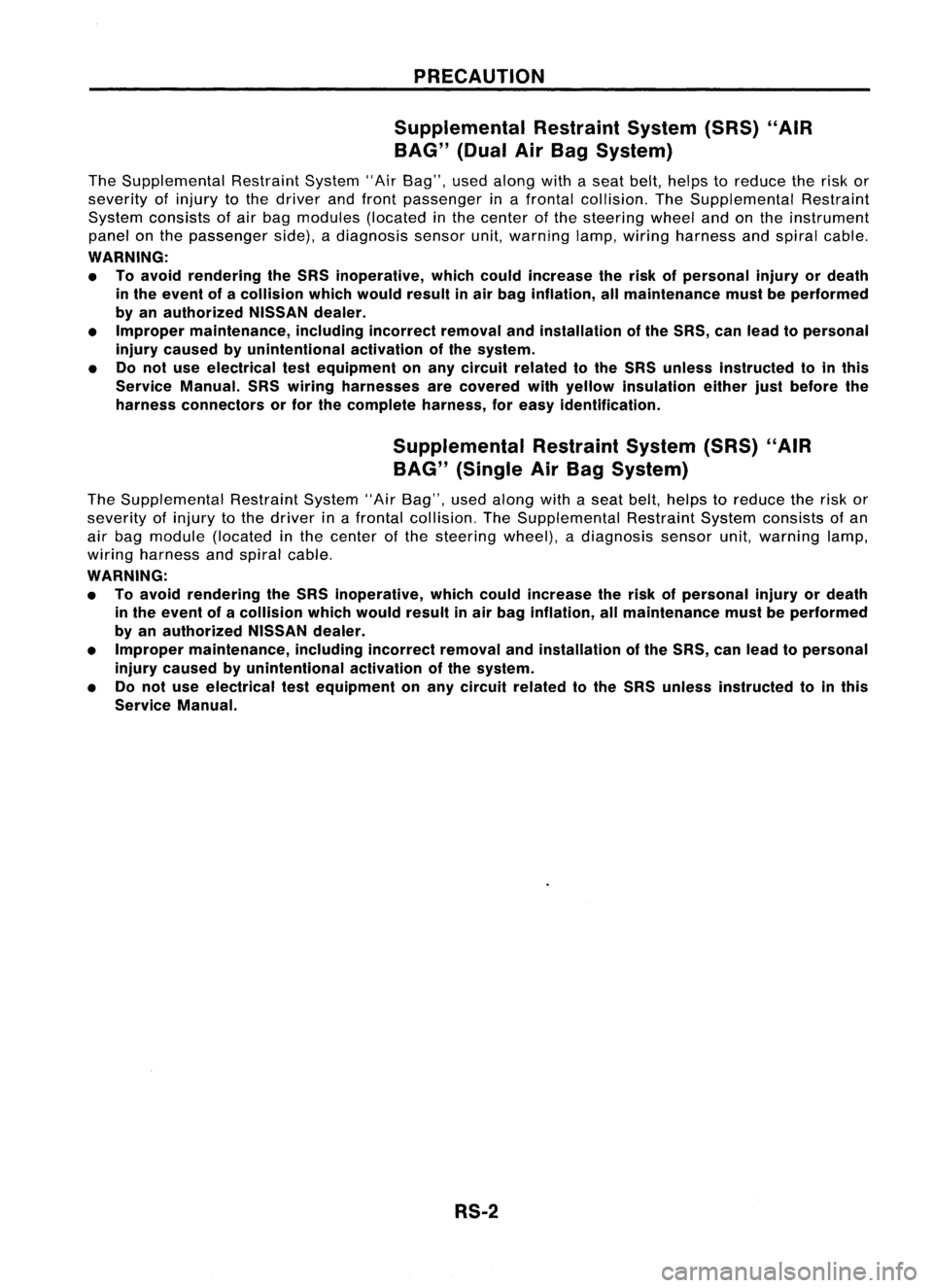
Supplemental RestraintSystem(SRS)"AIR
BAG" (DualAirBag System)
The Supplemental RestraintSystem"AirBag", usedalong withaseat belt, helps toreduce therisk or
severity ofinjury tothe driver andfront passenger inafrontal collision. TheSupplemental Restraint
System consists ofair bag modules (locatedinthe center ofthe steering wheelandonthe instrument
panel onthe passenger side),adiagnosis sensorunit,warning lamp,wiring harness andspiral cable.
WARNING:
• Toavoid rendering theSRS inoperative, whichcouldincrease therisk ofpersonal injuryordeath
in the event ofacollision whichwould resultinair bag inflation, allmaintenance mustbeperformed
by an authorized NISSANdealer.
• Improper maintenance, includingincorrectremovalandinstallation ofthe SRS, canlead topersonal
injury caused byunintentional activationofthe system.
• Donot use electrical testequipment onany circuit related tothe SRS unless instructed tointhis
Service Manual. SRSwiring harnesses arecovered withyellow insulation eitherjustbefore the
harness connectors orfor the complete harness,foreasy identification.
Supplemental RestraintSystem(SRS)"AIR
BAG" (Single AirBag System)
The Supplemental RestraintSystem"AirBag", usedalong withaseat belt, helps toreduce therisk or
severity ofinjury tothe driver inafrontal collision. TheSupplemental RestraintSystemconsists ofan
air bag module (located inthe center ofthe steering wheel),adiagnosis sensorunit,warning lamp,
wiring harness andspiral cable.
WARNING:
• Toavoid rendering theSRS inoperative, whichcouldincrease therisk ofpersonal injuryordeath
in the event ofacollision whichwould resultinair bag inflation, allmaintenance mustbeperformed
by an authorized NISSANdealer.
• Improper maintenance, includingincorrectremovalandinstallation ofthe SRS, canlead topersonal
injury caused byunintentional activationofthe system.
• Donot use electrical testequipment onany circuit related tothe SRS unless instructed tointhis
Service Manual.
RS-2
Page 1628 of 1701
SUPPLEMENTALRESTRAINTSYSTEM(SRS)
Precautions forSRS "AirBag" and"Seat Belt
Pre-tensioner" Service
• Donot use acircuit testertocheck SRScircuits.
• Before servicing theSRS. turnignition switch"OFF", disconnect bothbattery cablesandwait forat
least 10minutes.
For approximately 10minutes afterthecables areremoved, itis still possible forthe airbag to
deploy. Therefore, donot work onany SRS connectors orwires untilatleast 10minutes havepassed.
• For single airbag system, donot separate diagnosis sensorunitfrom steering wheel.
• For dual airbag system. diagnosis sensorunitmust always beinstalled withtheir arrow marks
"Q"
pointing towards thefront ofthe vehicle forproper operation. Alsocheck diagnosis sensorunitfor
cracks. deformities orrust before installation andreplace asrequired.
• The spiral cablemustbealigned withtheneutral position sinceitsrotations arelimited. Donot
attempt toturn steering wheelorcolumn afterremoval ofsteering gear.
• Handle airbag module carefully. Alwaysplaceitwith thepad side facing upward.
• Donot use oldbolts afterremoving anySRS parts; replace withnewones. Conduct self-diagnosis
to check entire SRSforproper function.
• For dual airbag system, instrument panelassembly shouldbereplaced afterairbag inflates.
X
X
Use
forspecial bolts
[TAMPER RESISTANT
TORX (SizeT50))
a:
3.5 (0.138)
dia.
b: 8.5 -8.6
(0.335 •0.339) dia.
c: approx.
10
(0.39) sq.
c
NT354
a
HT61961000
and
HT62152000 com-
bined *1 Special torxbit
Special
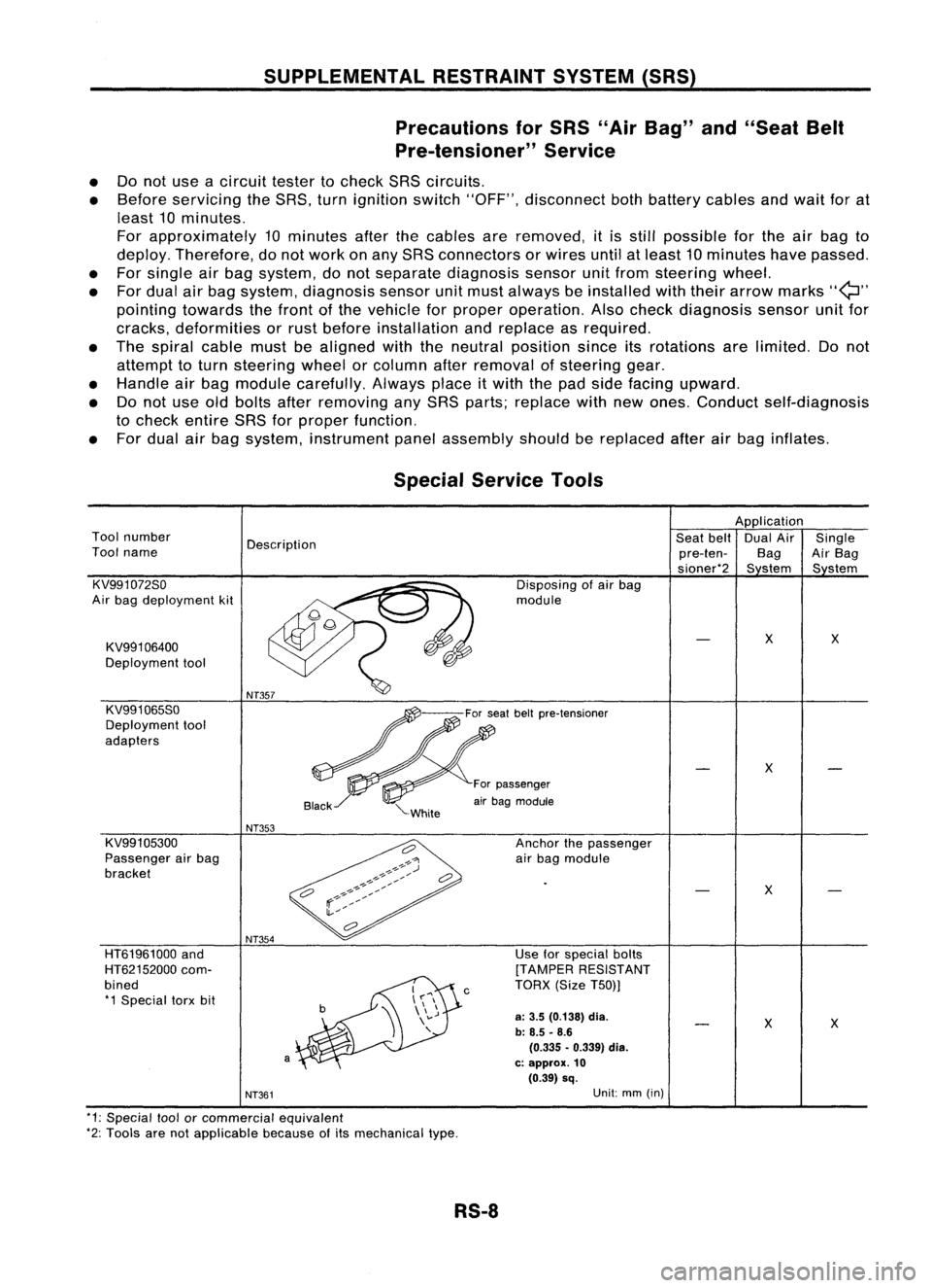
Service Tools
Application
Tool number
Description Seat
belt DualAir Single
Tool name
pre-ten-BagAirBag
sioner*2 Sstem Sstem
KV991072So Disposingofair bag
Air bag deployment kit module
KV991 06400
X
X
Deployment tool
KV991065So
Deployment tool
adapters
X
For passenger
air bag module
NT353
KV991 05300 Anchorthepassenger
Passenger airbag
airbag module
bracket
X
NT361
Unit:
mm(in)
*1: Special toolorcommercial equivalent
*2: Tools arenotapplicable becauseofits mechanical type.
RS-8
Page 1631 of 1701
SUPPLEMENTALRESTRAINTSYSTEM(SRS)
Visually checkSRScomponents
Diagnosis sensorunit
Check diagnosis sensorunitand bracket fordents, cracks
or deformities.
Check connectors fordamage, andterminals fordeformi-
ties.
Air bag module andsteering wheel
Remove airbag module fromsteering wheelorinstrument
panel. Check harness coverandconnectors fordamage,
terminals fordeformities, andharness forbinding.
Install driversideairbag module tosteering wheeltocheck
fit or alignment withthewheel.
Check steering wheelforexcessive freeplay.
For dual airbag system, installpassenger sideairbag
module toinstrument paneltocheck fitor alignment withthe
instrument panel.
Maintenance
Items
1. Check "AIRBAG" warning lampoperation
After turning ignition keyto"ON" position, "AIRBAG"
warning lampilluminates. The"AIR BAG" warning lamp
will turn offafter about 7seconds ifno malfunction is
detected. If any ofthe following airbag warning lampconditions
occur, immediately checktheairbag system. RefertoRS-32
and 43for details.
The warning lampdoesnotilluminate whentheignition
switch isturned "ON".
The warning lampdoesnotturn offabout 7seconds after
the ignition switchisturned "ON".
The warning lampturns offabout 7seconds aftertheigni-
tion switch isturned "ON",butitturns onorflashes again.
•
MRS115A
•
•
2. (1)
•
•
(2)
•
•
•
•
(3) Spiral cable
• Check spiralcablefordents, cracks, ordeformities.
• Check connectors andprotective tapefordamage.
• Check steering wheelfornoise, binding orheavy operation. •
(4) Main harness andairbag harness (Fordual airbag system
only)
• Check connectors forpoor connections, damage,andtermi-
nals fordeformities.
• Check harnesses forbinding, chafingorcut.
CAUTION: Replace previously usedscrews withnewones.
RS-11
Page 1632 of 1701
SUPPLEMENTALRESTRAINTSYSTEM(SRS)
Removal andInstallation -Diagnosis Sensor
Unit
CAUTION:
• Before servicing SRS,turntheignition switchoff,disconnect bothbattery cablesandwait foratleast
10 minutes.
• The special boltsarecoated withbonding agentwhiletheother boltisfor ground. Donot use old
bolts afterremoval; replacewithnewones.
• For single airbag system, donot separate diagnosis sensorunitfrom steering wheel.
• For dual airbag system, checkdiagnosis sensorunitforproper installation.
• Check diagnosis sensorunittoensure theyarefree ofdeformities, dents,cracks orrust. Ifthey show
any visible signsofdamage, replacethemwithnewones.
• Check diagnosis sensorunitbrackets toensure theyarefree ofdeformities orrust.
• Always workfromtheside ofair bag module.
• Replace diagnosis sensorunitifithas been dropped orsustained animpact.
SEC. 253~
IT
r
Grou~? bolt~
G ~~ ~
Forward mark
Fr?nt
_--I
d--!
Dia~no:iS senSlrunit
!
Special bOIt~ -
t"'J
15-25 N.m
(1.5 •2.5 kg-m,
11-
18 ft-Ib)
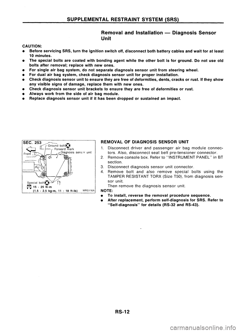
MRS116A REMOVAL
OFDIAGNOSIS SENSORUNIT
1. Disconnect driverandpassenger airbag module connec-
tors. Also, disconnect seatbeltpre-tensioner connector.
2. Remove consolebox.Refer to"INSTRUMENT PANEL"in8T
section.
3. Disconnect diagnosissensorunitconnector.
4. Remove boltandalso remove specialboltsusing the
TAMPER RESISTANT TORX(SizeT50),fromdiagnosis sen-
sor unit.
Then remove thediagnosis sensorunit.
NOTE:
• Toinstall, reverse theremoval procedure sequence.
• After replacement, performself-diagnosis forSRS. Refer to
"Self-diagnosis" fordetails (RS-32andRS-43).
RS-12
Page 1634 of 1701
SUPPLEMENTALRESTRAINTSYSTEM(SRS)
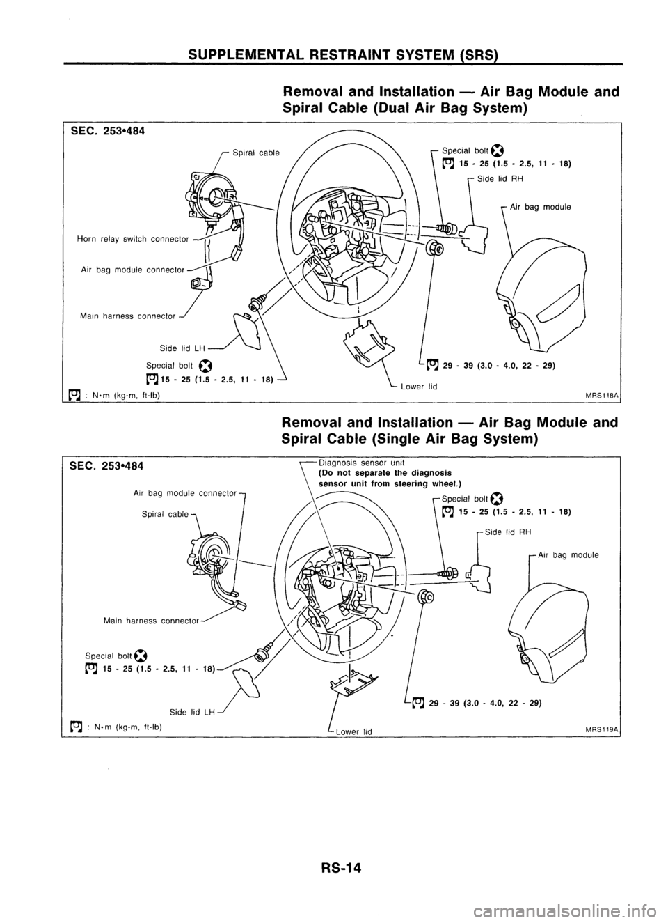
Removal andInstallation -Air Bag Module and
Spiral Cable(DualAirBag System)
SEC. 253-484
Horn relayswitch connector
Special bolt~
to:J
15-25 (1.5 -2.5,
11-
18)
to:J :
N.m (kg-m. ft-Ib) Special
bolt~
to:J
15.25 (1.5•2.5,
11•
18)
Side lidRH
Air bag module
to:J
29-39 (3.0 -4.0, 22-29)
Lower lid
MRS118A
Removal andInstallation -Air Bag Module and
Spiral Cable(Single AirBag System)
SEC. 253-484
Airbag module connector
Spiral cable
A'
Special bolt~ ~
t"J
15•25 (1.5 •2.5, 11•18)- ~
Side lidLH/
"-J
to:J :
N. m (kg-m. ft-Ib) ~DiagnOSiS
sensorunit
(Do notseparate thediagnosis
sensor unitfrom steering wheel.)
Special boll~
to:J
15-25 (1.5 -2.5,
11-
18)
~~ r
S;d, lidRH
~ (]A;,b'9
mod",
MRS119A
RS-14