Page 1249 of 1701
TIMINGCHAIN [][]
Removal (Conl'd)
13. Remove oilfilter bracket andpower steering oilpump
bracket.
14. Set NO.1 piston at
TOG
onthe compression strokebyrotat-
ing crankshaft.
• Rotate crankshaft untilmating markoncamshaft sprocketis
set atposition indicated infigure atleft.
15. Remove chaintensioner.
16. Remove distributor.
Do not turn rotor withdistributor removed.
EM-70
Page 1259 of 1701
SEM990C
SEM991C TIMING
CHAIN
[]K]
Installation (Cont'd)
23. Install distributor.
• Make surethatposition ofcamshaft isas shown infigure.
• Make surethatNo.1 piston isset at
TOe
andthat distribu-
tor isset atNo.1 cylinder sparkposition.
24. Install chaintensioner.
Make surethecamshaft sprockets aretightened completely.
Press camstopper downand"press-in" sleeveuntilhook can
be engaged onpin. When tensioner isbolted inposition the
hook willrelease automatically. Makesurearrow "A"points
toward enginefront.
25. Install oilfilter bracket andpower steering oilpump bracket.
EM-80
Page 1260 of 1701
Unit:mm(in)
10
(0.39)
n'
Engine front
1+ .,..I
3 (0.12) ~LiqUid
gasket
SEM366D TIMING
CHAIN
Installation (Cont'd)
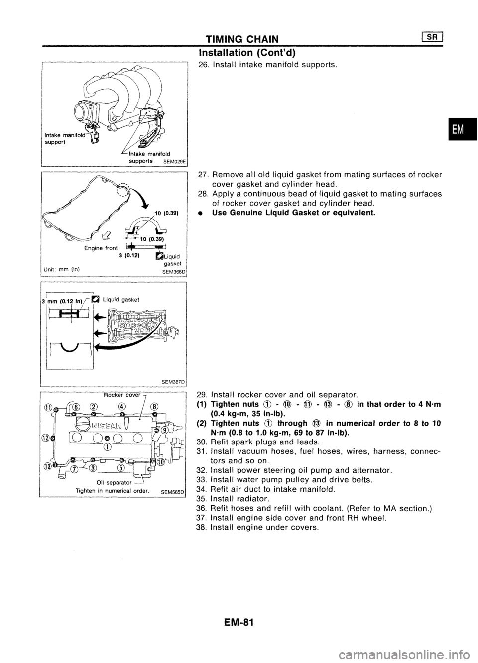
26. Install intakemanifold supports.
27. Remove allold liquid gasket frommating surfaces ofrocker
cover gasket andcylinder head.
28. Apply acontinuous beadofliquid gasket tomating surfaces
of rocker covergasket andcylinder head.
• Use Genuine LiquidGasket orequivalent.
•
3
1
mm (0.12
In)r~
liquidgasket
tJ$j
SEM367D
@
8l"-L~~[c,.l~
Q
[0 O@O 0
CD
Oil separator
Tighten innumerical order.
SEM585D
29.
Install rocker coverandoilseparator.
(1) Tighten nuts
C!J-
@l -
@ -@ -
cID
inthat order to4N'm
(0.4 kg-m, 35in-Ib).
(2) Tighten nuts
d)
through @innumerical orderto8to 10
N'm (0.8to1.0 kg-m, 69to87 in-Ib).
30. Refit spark plugsandleads.
31. Install vacuum hoses,fuelhoses, wires,harness, connec-
tors andsoon.
32. Install power steering oilpump andalternator.
33. Install waterpumppulley anddrive belts.
34. Refit airduct tointake manifold.
35. Install radiator.
36. Refit hoses andrefill withcoolant. (RefertoMA section.)
37. Install engine sidecover andfront RHwheel.
38. Install engine undercovers.
EM-81
Page 1278 of 1701
SEM092DENGINE
REMOVAL
WARNING:
• Situate vehicle onaflat and solid surface.
• Place chocks atfront andback ofrear wheels.
• Donot remove engineuntilexhaust systemhascompletely
cooled off.
Otherwise, youmay burn yourself and/orfiremay break out
in fuel line.
• For safety during subsequent steps,thetension ofwires
should beslackened againsttheengine.
• Before disconnecting fuelhose, release fuelpressure from
fuel line.
Refer to"Releasing FuelPressure" inEC section.
• Besure tohoist engine andtransaxle inasafe manner.
• For engines notequipped withengine slingers, attach
proper slingers andbolts described inPARTS CATALOG.
CAUTION:
• When liftingengine, becareful nottostrike adjacent parts,
especially thefollowing: Accelerator wirecasing, brake
lines, andbrake master cylinder.
• Inhoisting theengine, alwaysuseengine slingers inasafe
manner.
Removal
1. Remove engineundercoverandhood.
2. Drain coolant frombothcylinder block,andradiator.
3. Drain engine oilfrom drain plugofoil pan.
4. Remove vacuumhoses,fuelhoses, wires,harness andcon-
nectors andsoon.
5. Remove exhausttubes,balljoints anddrive shafts.
6. Remove radiatorandfans.
7. Remove drivebelts.
8. Remove alternator, compressor andpower steering oil
pump fromengine.
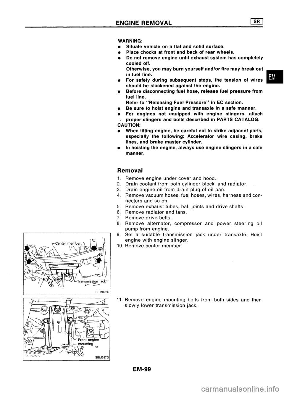
9. Set asuitable transmission jackunder transaxle. Hoist
engine withengine slinger.
10. Remove centermember.
11. Remove enginemounting boltsfrombothsides andthen
slowly lowertransmission jack.
EM-99
•
Page 1280 of 1701
CYLINDERBLOCK
SEC.
Snapring~
f)
to:J
Refer to
"ASSembIY"'-~
: Apply liquidgasket.
Lubricate withnew engine
011
•
CD
Rear oilseal retainer
@
Cylinder block
@
Water pump
@
Power steering oilpump
adjusting bar
@
Front cover withoilpump
@
Oilstrainer
(J)
Thrust bearing
@
Crankshaft
@
Connecting rodbushing
@J
Piston rings
@
Piston
@
Piston pin
@
Connecting rod
@
Connecting rodbearing
@
Baffle plate
@
Aluminum oilpan
@
Rear cover plate
@
Drain plug
@J
Steel oilpan
@
Baffle plate
EM-101 @
Side gallery baffleplate
@
Main bearing beam
@
Main bearing cap
@
Pilotconverter
@
Drive plate
@
Reinforcement plate
@
Flywheel
@
Pilotbushing
@
Rear plate
@
Main bearing
Page 1320 of 1701
Drainplug(Radiator)
SFA110A
SFA 1538
SEM534D ENGINE
REMOVAL
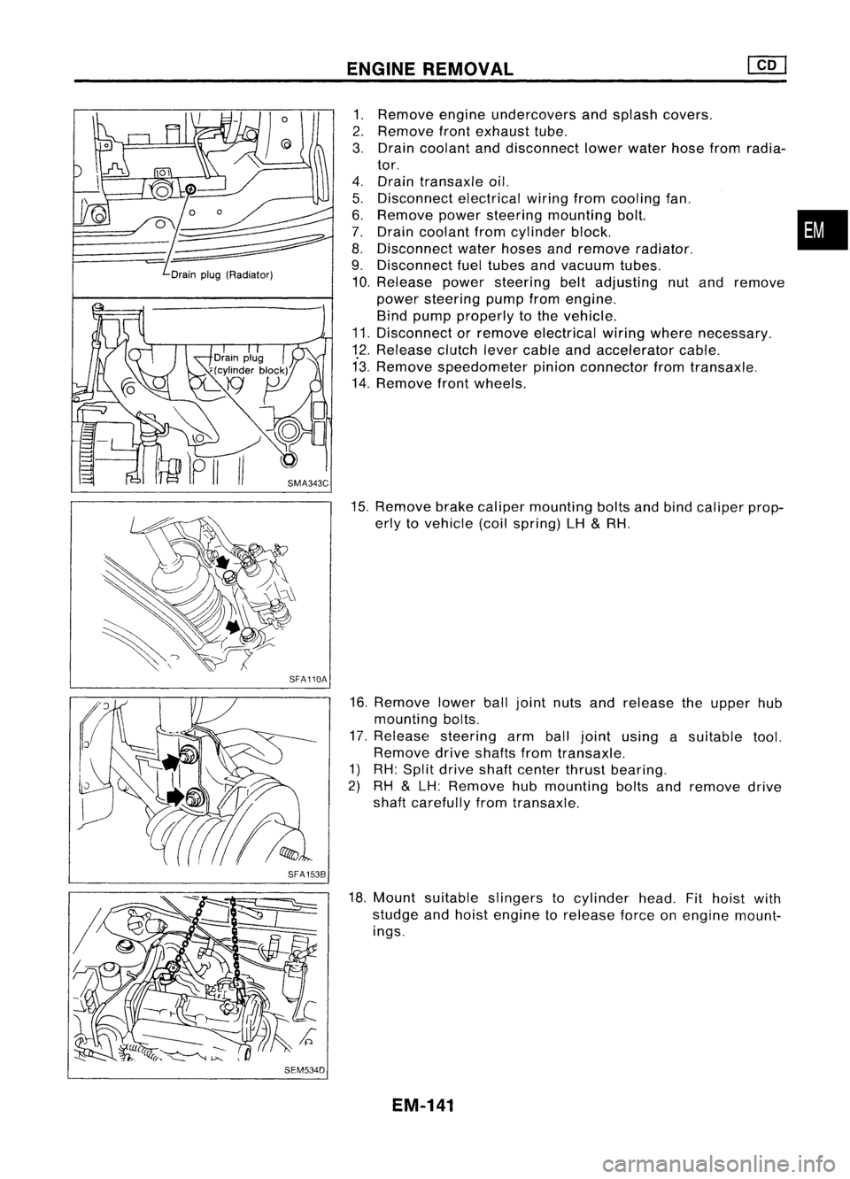
1. Remove engineundercovers andsplash covers.
2. Remove frontexhaust tube.
3. Drain coolant anddisconnect lowerwater hosefromradia-
tor.
4. Drain transaxle oil.
5. Disconnect electricalwiringfromcooling fan.
6. Remove powersteering mounting bolt. •
7. Drain coolant fromcylinder block.
8. Disconnect waterhoses andremove radiator.
9. Disconnect fueltubes andvacuum tubes.
10. Release powersteering beltadjusting nutand remove
power steering pumpfromengine.
Bind pump properly tothe vehicle.
11. Disconnect orremove electrical wiringwhere necessary.
12. Release clutchlevercable andaccelerator cable.
13. Remove speedometer pinionconnector fromtransaxle.
14. Remove frontwheels.
15. Remove brakecaliper mounting boltsandbind caliper prop-
erly tovehicle (coilspring) LH
&
RH.
16. Remove lowerballjoint nutsandrelease theupper hub
mounting bolts.
17. Release steering armballjoint using asuitable tool.
Remove driveshafts fromtransaxle.
1) RH: Split drive shaftcenter thrustbearing.
2) RH
&
LH: Remove hubmounting boltsandremove drive
shaft carefully fromtransaxle.
18. Mount suitable slingers tocylinder head.Fithoist with
studge andhoist engine torelease forceonengine mount-
ings.
EM-141
Page 1356 of 1701
PRECAUTIONS
Observe thefollowing precautions toensure safeandproper
servicing.
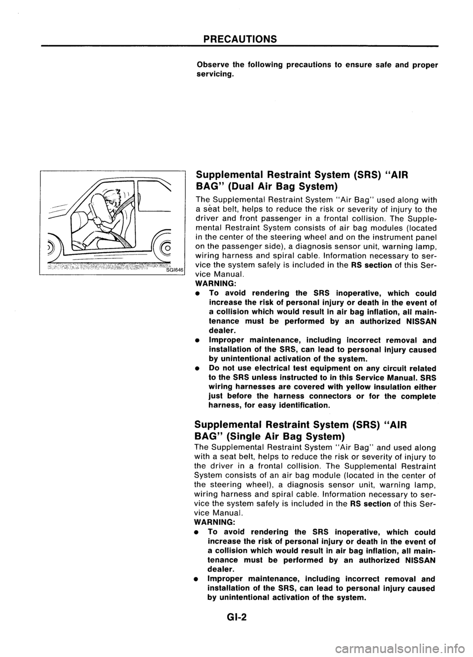
Supplemental RestraintSystem(SRS)"AIR
BAG" (DualAirBag System)
The Supplemental RestraintSystem"AirBag" usedalong with
a seat belt,helps toreduce therisk orseverity ofinjury tothe
driver andfront passenger inafrontal collision. TheSupple-
mental Restraint Systemconsists ofair bag modules (located
in the center ofthe steering wheelandonthe instrument panel
on the passenger side),adiagnosis sensorunit,warning lamp,
wiring harness andspiral cable. Information necessarytoser-
vice thesystem safelyisincluded inthe RSsection ofthis Ser-
vice Manual.
WARNING:
• To avoid rendering theSRS inoperative, whichcould
increase therisk ofpersonal injuryordeath inthe event of
a collision whichwould resultinair bag inflation, allmain-
tenance mustbeperformed byan authorized NISSAN
dealer.
• Improper maintenance, includingincorrectremovaland
installation ofthe SRS, canlead topersonal injurycaused
by unintentional activationofthe system.
• Donot use electrical testequipment onany circuit related
to the SRS unless instructed tointhis Service Manual. SRS
wiring harnesses arecovered withyellow insulation either
just before theharness connectors orfor the complete
harness, foreasy identification.
Supplemental RestraintSystem(SRS)"AIR
BAG" (Single AirBag System)
The Supplemental RestraintSystem"AirBag" andused along
with aseat belt, helps toreduce therisk orseverity ofinjury to
the driver inafrontal collision. TheSupplemental Restraint
System consists ofan air bag module (located inthe center of
the steering wheel),adiagnosis sensorunit,warning lamp,
wiring harness andspiral cable. Information necessarytoser-
vice thesystem safelyisincluded inthe RSsection ofthis Ser-
vice Manual.
WARNING:
• To avoid rendering theSRS inoperative, whichcould
increase therisk ofpersonal injuryordeath inthe event of
a collision whichwould resultinair bag inflation, allmain-
tenance mustbeperformed byan authorized NISSAN
dealer.
• Improper maintenance, includingincorrectremovaland
installation ofthe SRS, canlead topersonal injurycaused
by unintentional activationofthe system.
GI-2
Page 1362 of 1701
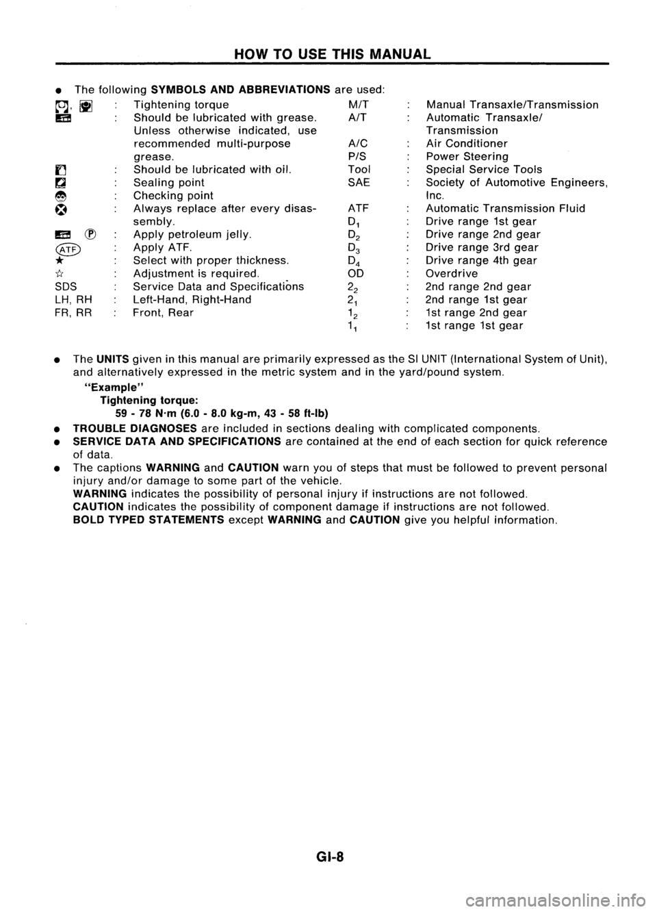
HOWTOUSE THIS MANUAL
ManualTransaxle/Transmission
Automatic Transaxle/
Transmission
Air Conditioner
Power Steering
Special Service Tools
Society ofAutomotive Engineers,
Inc.
Automatic Transmission Fluid
Drive range 1stgear
Drive range 2ndgear
Drive range 3rdgear
Drive range 4thgear
Overdrive
2nd range 2ndgear
2nd range 1stgear
1st range 2ndgear
1st range 1stgear
A/C
PIS
Tool SAE
ATF
0
1
O
2
0
3
0
4
00
2
2
2
1
1
2
1
1
•
The following
SYMBOLS ANDABBREVIATIONS
areused:
to;J,
l\tI
Tightening torque M/T
IE!
Shouldbelubricated withgrease. A/T
Unless otherwise indicated,use
recommended multi-purpose
grease.
Should belubricated withoil.
Sealing point
Checking point
Always replaceafterevery disas-
sembly.
Apply petroleum jelly.
Apply ATF.
Select withproper thickness.
Adjustment isrequired.
Service DataandSpecifications
Left-Hand, Right-Hand
Front, Rear
IE!
~
@
*
1I
SDS LH, RH
FR, RR
• The
UNITS
giveninthis manual areprimarily expressed asthe SlUNIT (International SystemofUnit),
and alternatively expressedinthe metric system andinthe yard/pound system.
"Example" Tightening torque:
59 -78 N'm (6.0-8.0 kg-m, 43-58 ft-Ib)
• TROUBLE DIAGNOSES
areincluded insections dealingwithcomplicated components.
• SERVICE DATAANDSPECIFICATIONS
arecontained atthe end ofeach section forquick reference
of data.
• The captions
WARNING
and
CAUTION
warnyouofsteps thatmust befollowed toprevent personal
injury and/or damage tosome partofthe vehicle.
WARNING
indicatesthepossibility ofpersonal injuryifinstructions arenotfollowed.
CAUTION
indicatesthepossibility ofcomponent damageifinstructions arenotfollowed.
BOLD TYPED STATEMENTS
except
WARNING
and
CAUTION
giveyouhelpful information.
GI-8