1995 NISSAN ALMERA N15 steering
[x] Cancel search: steeringPage 890 of 1701

•
INSPECTION END
OK
The
power steering oilpressure switchisattached tothe power
steering high-pressure tubeanddetects apower steering load.
When apower steering loadisdetected,
it
signals theECM. The
ECM adjusts theIACV-AAC valvetoincrease theidle speed and
adjust forthe increased load.
INSPECTION START
OR
1. Start engine.
2. Check voltage between ECM
terminal
@
or
@
and ground.
Voltage: When steering wheelis
turned quickly.
Approximately OV
Except above
Approximately 5V
NG
DIAGNOSTIC
PROCEDURE
CHECK OVERALL FUNCTION.
fiii\
1.Turn ignition switch"ON".
~ 2.Perform "PW/STSIGNAL
CIRCUIT" in"FUNCTION
TEST" modewithCONSULT.
OR
(F.i\
1.Start engine.
~ 2.Check "PW/ST SIGNAL" in
"DATA MONITOR" modewith
CONSULT.
Steering isin neutral
position: OFF
Steering isturned:
ON
SEF591I
SEF235R
MEF023E
Power
steering oil___
pressure switch
-
~
to
TROUBLE
DIAGNOSIS FORNON-DETECTABLE ITEMS
@[]
Power Steering OilPressure Switch(Cont'd)
COMPONENT DESCRIPTION
RECORD
NEXT
II
START
•
PW/ST SIGNAL CIRCUIT.
HOLD STEERING WHEEL
IN AFULL
LOCKED
POSITION
THEN
TOUCH START
* MONITOR *NO FAIL
0
PW/ST SIGNAL OFF
@):
ForAustralia
@:
Except forAustralia
~i)~
II
ECM
Ef
CONNECTOR
II
43 25
EC-171
Page 891 of 1701
![NISSAN ALMERA N15 1995 Service Manual TROUBLEDIAGNOSIS FORNON-DETECTABLE ITEMS
@K]
Power Steering OilPressure Switch(Cont'd)
@:
ForAustralia
@:
Except forAustralia SEF176R
Repair
harness orcon-
nectors.
CHECK INPUTSIGNAL CIRCUIT. NISSAN ALMERA N15 1995 Service Manual TROUBLEDIAGNOSIS FORNON-DETECTABLE ITEMS
@K]
Power Steering OilPressure Switch(Cont'd)
@:
ForAustralia
@:
Except forAustralia SEF176R
Repair
harness orcon-
nectors.
CHECK INPUTSIGNAL CIRCUIT.](/manual-img/5/57349/w960_57349-890.png)
TROUBLEDIAGNOSIS FORNON-DETECTABLE ITEMS
@K]
Power Steering OilPressure Switch(Cont'd)
@:
ForAustralia
@:
Except forAustralia SEF176R
Repair
harness orcon-
nectors.
CHECK INPUTSIGNAL CIRCUIT. NG
Check thefollowing .
1. Disconnect ECMharness connector.
......---..
•Harness connectors
2. Check harness continuity between
aD,
(MID
ECM terminal
@
or
@
and terminal •
Harness connectors
G).
@,@or@,
Continuity shouldexist.
If
OK, check harness forshort. •
Harness foropen or
OK short
between ECMand
power steering oilpres-
sure switch
If NG, repair harness or
connectors.
CHECK COMPONENT NG
Replace powersteering
(Power steering oilpressure switch).
--...
oilpressure switch.
Refer to"COMPONENT INSPECTION"
below.
OK
Disconnect andreconnect harnesscon-
nectors inthe circuit. Thenretest.
Trouble isnot fixed.
Check ECMpinterminals fordamage or
the connection ofECM harness connec-
tor. Reconnect ECMharness connector
and retest.
@
1
CHECK GROUND CIRCUIT.
1. Turn ignition switch"OFF".
2. Disconnect powersteering oilpres-
sure switch harness connector.
3. Check harness continuity between
terminal
@
and engine ground.
Continuity shouldexist.
AEC760
IfOK, check harness forshort.
~i5
[i
c:ITb
~i5
ECM
Ef
CONNECTOR
II
43 25
II
INSPECTIONEND
Power steering oilpressure switch
1. Disconnect powersteering oilpressure switchharness con-
nector thenstart engine.
2. Check continuity betweenterminals
@.
[At
IV
ID
~ COMPONENT
INSPECTION
Conditions
Steering wheelisbeing turned
Steering wheelisnot being turned Continuity
Yes
No
AEC762
IfNG, replace powersteering oilpressure switch.
EC-172
Page 911 of 1701
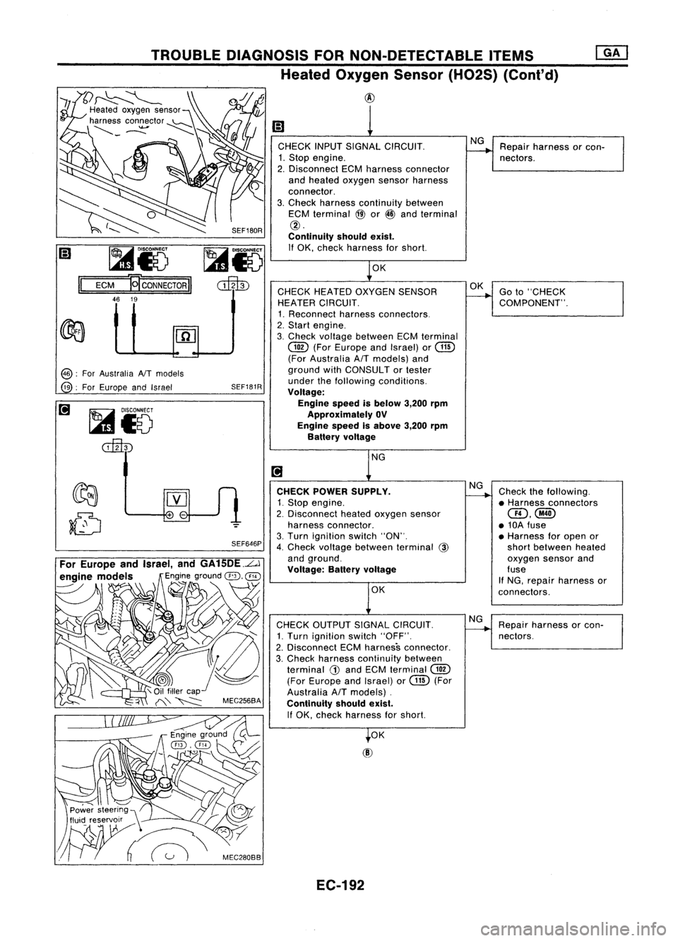
I;)
1
CHECK INPUTSIGNAL CIRCUIT. NG
Repair harness orcon-
1. Stop engine.
--.
nectors.
2. Disconnect ECMharness connector
and heated oxygen sensorharness
connector.
3. Check harness continuity between
ECM terminal
@
or
@
and terminal
@.
Continuity shouldexist.
If OK, check harness forshort.
1
0K
CHECK HEATED OXYGEN SENSOR OK
Goto"CHECK
HEATER CIRCUIT.
--.
COMPONENT".
1. Reconnect harnessconnectors.
2. Start engine.
3. Check voltage between ECMterminal
@
(ForEurope andIsrael) or
@
(For Australia AfTmodels) and
ground withCONSULTor tester
under thefollowing conditions.
Voltage:
Engine speedisbelow 3,200rpm
Approximately OV
Engine speedisabove 3,200rpm
Battery voltage
NG
[!J
CHECK POWER SUPPLY. NG
Check thefollowing.
1. Stop engine.
~
•Harness connectors
2. Disconnect heatedoxygen sensor
aD,@
harness connector. •10A fuse
3. Turn ignition switch"ON".
•Harness foropen or
4. Check voltage between terminal
@
shortbetween heated
and ground. oxygensensorand
Voltage: Batteryvoltage fuse
If NG, repair harness or
OK connectors.
CHECK OUTPUT SIGNALCIRCUIT. NG
Repair harness orcon-
1. Turn ignition switch"OFF".
-----...
nectors.
2. Disconnect ECMharness connector.
3, Check harness continuity between
terminal
G)
and ECM terminal
@
(For Europe andIsrael) orGill (For
Australia
AfT
models) .
Continuity shouldexist.
If OK, check harness forshort.
t
OK
SEF180R
SEF646P
SEF181R
~i5
cilltD
@:
ForAustralia NTmodels
@:
ForEurope andIsrael
TROUBLE
DIAGNOSIS FORNON-DETECTABLE ITEMS
Heated Oxygen Sensor(H02S) (Cont'd)
@
~
~
I;) ~i5
Il
ECM
'QcoNNECTORII
46 19
For Europe andIsrael, andGA15DE.L.J
engine models
Engineground
@,
@
----- \
~ ~
'1
\
.~
,~\ C/
Power steering",
fluid reservoir __\ ~
W~
:'C"",,
EC-192
Page 951 of 1701
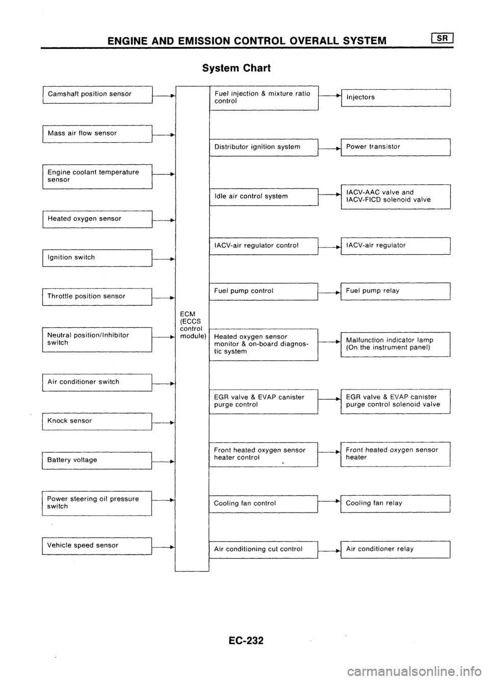
ENGINEANDEMISSION CONTROLOVERALLSYSTEM
System Chart
Camshaft positionsensor Fuel
injection
&
mixture ratio
•
I
I
control Injectors
Mass airflow sensor
I
Distributorignitionsystem
r
~1
Power transistor
Engine coolant temperature
.
sensor
I
IACV-AAC valveand
Idle aircontrol system
IACV-FICDsolenoidvalve
Heated oxygen sensor
I
IACV-airregulator control
~--..j
IACV-air regulator
I
Ignition switch
I
I
Throttle position sensor
~-+
Fuel
pump control Fuel
pump relay
ECM
(ECCS
control
Neutral position/Inhibitor
.
module) Heatedoxygen sensor
switch monitor
&
on-board diagnos-
~-+
Malfunction
indicatorlamp
tic system (On
theinstrument panel)
I
Air conditioner switch
t~
EGRvalve
&
EVAP canister
1---+
EGR
valve
&
EVAP canister
purge control purge
control solenoid valve
Knock sensor
.....
Frontheated oxygen sensor Front
heated oxygen sensor
Battery voltage
.
heater
control heater
I
.
Power steering oilpressure
~
Coolingfancontrol
--
Cooling
fanrelay
switch
Vehicle speedsensor
.....
Airconditioning cutcontrol Air
conditioner relay
EC-232
Page 974 of 1701
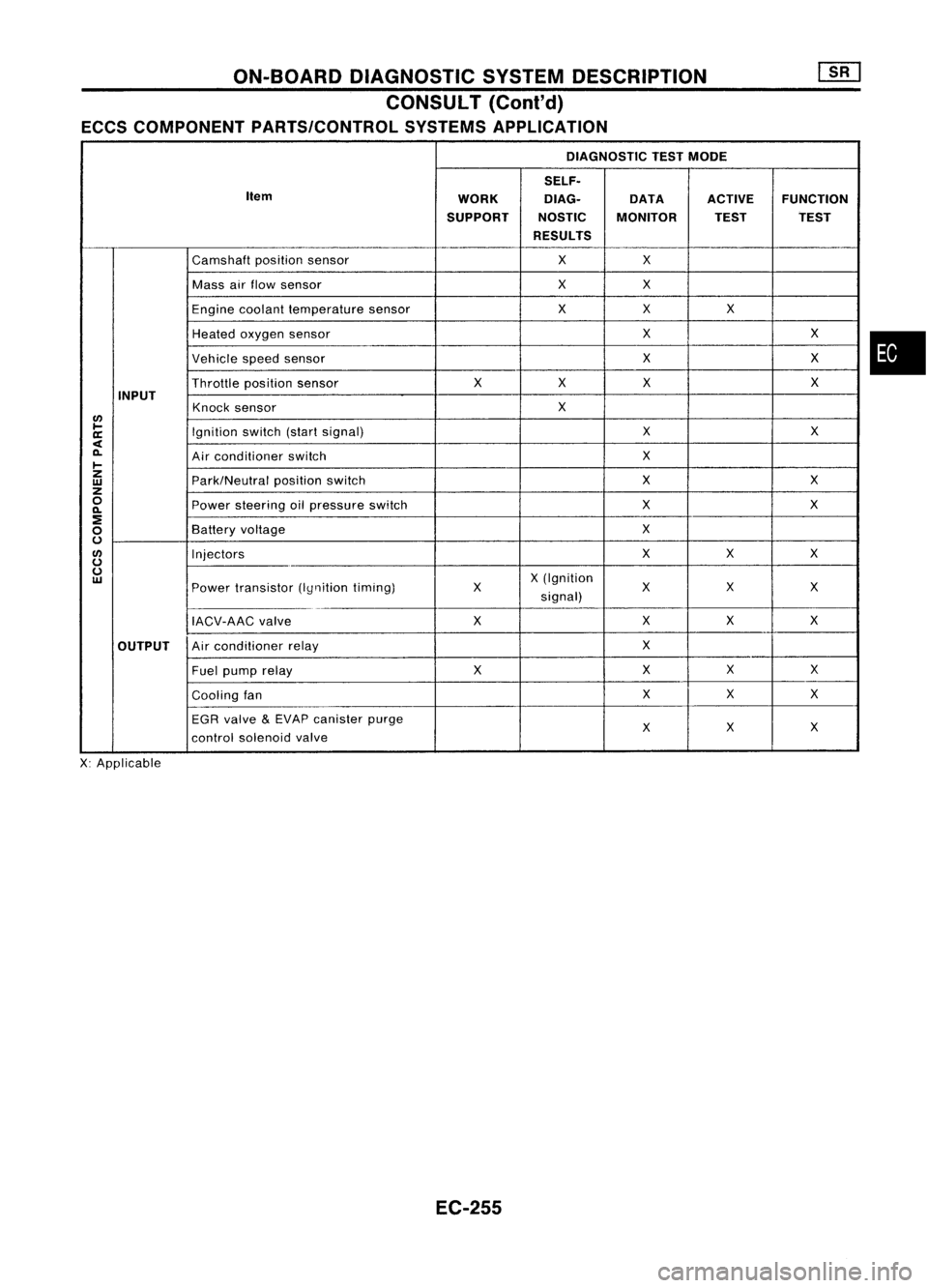
ON-BOARDDIAGNOSTIC SYSTEMDESCRIPTION
CONSULT (Coni'd)
ECCS COMPONENT PARTS/CONTROL SYSTEMSAPPLICATION
DIAGNOSTIC TESTMODE
SELF.
Item WORKDlAG.
DATAACTIVEFUNCTION
SUPPORT NOSTICMONITOR TESTTEST
RESULTS
Camshaft positionsensor XX
Mass airflow sensor XX
Engine coolant temperature sensor XX
X
Heated oxygen sensor X
X
Vehicle speedsensor X
X
Throttle positionsensor X
XX X
INPUT Knocksensor X
lJ)
~ Ignitionswitch(startsignal) X
X
a:
<
0-
Airconditioner switch X
~
z
Park/Neutralpositionswitch X
X
w
z
0
Powersteering oilpressure switch X
X
0-
:!
X
0
Battery
voltage
0
lJ)
Injectors XX
X
0
0
X(Ignition
w
Powertransistor (Iynitiontiming) X
XX
X
signal)
IACV-AAC valve XX
XX
OUTPUT Air
conditioner relay X
Fuel pump relay XXX
X
Cooling fan X
X
X
EGR valve
&
EVAP canister purge
X
X
X
control solenoid valve
X: Applicable
EC-255
•
Page 977 of 1701
![NISSAN ALMERA N15 1995 Service Manual ON-BOARDDIAGNOSTIC SYSTEMDESCRIPTION
CONSULT (Conl'd)
Monitored item ECM
Main
[Unit] input
signals Description
Remarks
signals
AIR COND SIG •Indicates [ON/OFF] conditionofthe
[ON/OFF]
00
air
NISSAN ALMERA N15 1995 Service Manual ON-BOARDDIAGNOSTIC SYSTEMDESCRIPTION
CONSULT (Conl'd)
Monitored item ECM
Main
[Unit] input
signals Description
Remarks
signals
AIR COND SIG •Indicates [ON/OFF] conditionofthe
[ON/OFF]
00
air](/manual-img/5/57349/w960_57349-976.png)
ON-BOARDDIAGNOSTIC SYSTEMDESCRIPTION
CONSULT (Conl'd)
Monitored item ECM
Main
[Unit] input
signals Description
Remarks
signals
AIR COND SIG •Indicates [ON/OFF] conditionofthe
[ON/OFF]
00
air
conditioner switchasdetermined
by the airconditioning signal.
PIN POSI SW
00
•
Indicates [ON/OFF] conditionfromthe
[ON/OFF] park/neutralpositionswitchsignal.
PW/ST SIGNAL •Indicates [ON/OFF] conditionofthe
[ON/OFF]
00
power
steering oilpressure switch
determined bythe power steering oil
pressure signal.
INJ PULSE [msec]
0
•
Indicates theactual fuelinjection •
When theengine isstopped, acertain
pulse widthcompensated byECM computedvalueisindicated.
according tothe input signals.
IGN TIMING [BTDC]
0
•
Indicates theignition timingcomputed
by ECM according tothe input sig-
nals.
IACV-AACIV
[%]
•Indicates theidle aircontrol valve
0
(AAC
valve) control valuecomputed
by ECM according tothe input sig-
nals.
A/F ALPHA [%J •Indicates themean valueofthe air- •When theengine isstopped, acertain
0
fuel
ratio feedback correction factor valueisindicated.
per cycle. •This dataalsoincludes thedata for
the air-fuel ratiolearning control.
AIR COND RLY •Indicates theairconditioner relay
[ON/OFF]
0
control
condition (determined byECM
according tothe input signal).
FUEL PUMP RLY •Indicates thefuel pump relaycontrol
[ON/OFFJ
0
condition
determined byECM accord-
ing tothe input signals.
COOLING FAN
•Indicates thecontrol condition ofthe
[HI/LOW/OFFJ coolingfans(determined byECM
0
according
tothe input signal).
HI ...High speed operation
LOW ...Low speed operation
OFF ...Stopped
EGRC SOLIV •Indicates thecontrol condition ofthe
[ON/OFFJ EGR
valve
&
EVAP canister Purge
control solenoid valve(determined by
0
ECM
according tothe input signal).
ON ...EGR andEVAP canister purge
operation cut-off
OFF ...EGR andEVAP canister purge
operation notcut-off
VOLTAGE •Voltage measured bythe voltage
[V] probe.
PULSE •Pulse width, frequency orduty cycle •Only "#"isdisplayed ifitem is
[msec] or[Hz] or
measuredbythe pulse probe. unabletobe measured.
[%]
•Figures with"#"s aretemporary
ones. Theyarethesame figures as
an actual pieceofdata which wasjust
previously measured.
EC-258
Page 980 of 1701
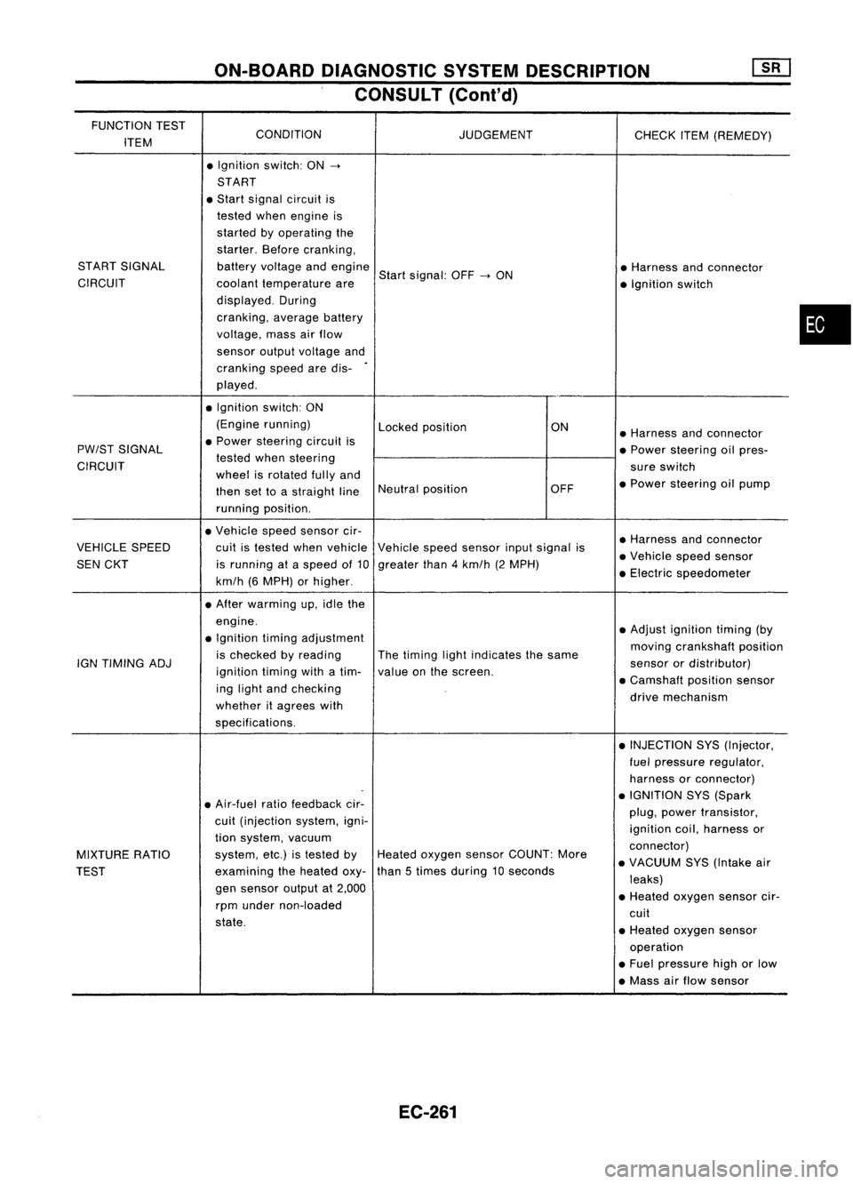
ON-BOARDDIAGNOSTIC SYSTEMDESCRIPTION
CONSULT (Cont'd)
FUNCTION TEST
CONDITION
ITEM JUDGEMENT
CHECKITEM(REMEDY)
• Ignition switch:ON
->
START
• Start signal circuit is
tested whenengine is
started byoperating the
starter. Beforecranking,
START SIGNAL batteryvoltage andengine
Startsignal: OFF
->
ON •
Harness andconnector
CIRCUIT coolanttemperature are
•Ignition switch
displayed. During
cranking, averagebattery
voltage, massairflow
sensor outputvoltage and
cranking speedaredis-
.
played .
• Ignition switch:ON
(Engine running)
Lockedposition ON
•Harness andconnector
PW/ST SIGNAL •
Power steering circuitis
•Power steering oilpres-
CIRCUIT tested
whensteering
sureswitch
wheel isrotated fullyand
•Power steering oilpump
then settoastraight lineNeutral
position OFF
running position.
• Vehicle speedsensor cir-
•Harness andconnector
VEHICLE SPEED cuitistested whenvehicle Vehiclespeedsensor inputsignal is
•Vehicle speedsensor
SEN CKT isrunning ataspeed of10 greater than4km/h (2MPH)
•Electric speedometer
km/h (6MPH) orhigher .
• After warming up,idle the
engine. •Adjust ignition timing(by
• Ignition timingadjustment
movingcrankshaft position
is checked byreading Thetiming lightindicates thesame
IGN TIMING ADJ
ignitiontimingwithatim- valueonthe screen. sensor
ordistributor)
ing light andchecking •
Camshaft positionsensor
whether itagrees with drive
mechanism
specifications. •INJECTION SYS(Injector,
fuel pressure regulator,
harness orconnector)
• Air-fuel ratiofeedback cir- •
IGNITION SYS(Spark
cuit (injection system,igni- plug,
power transistor,
ignition coil,harness or
tion system, vacuum
connector)
MIXTURE RATIO system,
etc.)istested byHeated oxygen sensorCOUNT: More
•VACUUM SYS(Intake air
TEST examining
theheated oxy-than
5times during 10seconds
leaks)
gen sensor outputat2,000
•Heated oxygen sensorcir-
rpm under non-loaded
cuit
state. •Heated oxygen sensor
operation
• Fuel pressure highorlow
• Mass airflow sensor
EC-261
•
Page 990 of 1701
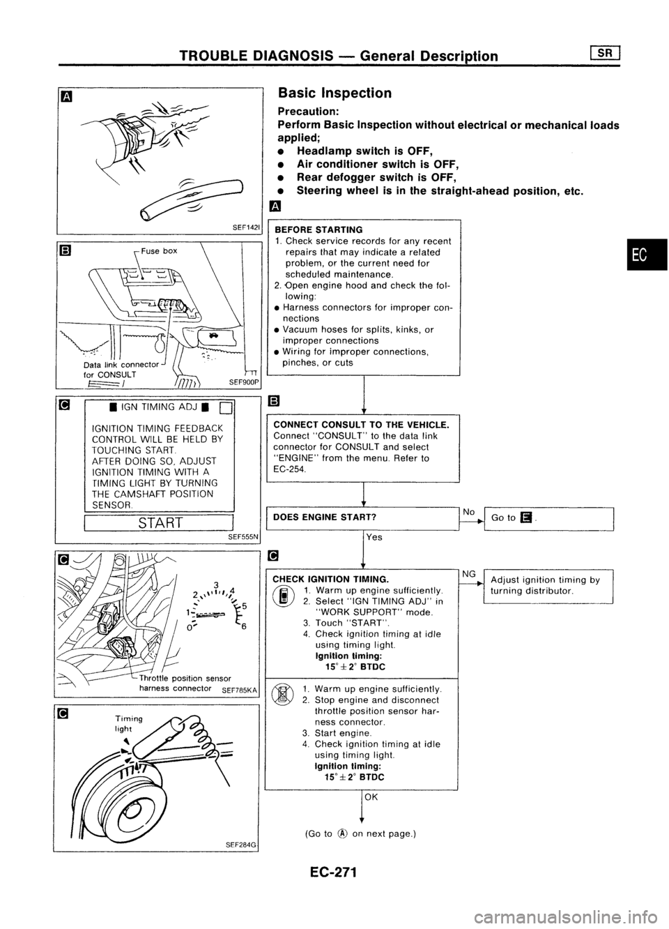
TROUBLEDIAGNOSIS -General Descrip_ti_on
1S_R_'
Basic Inspection
Precaution:
Perform BasicInspection withoutelectrical ormechanical loads
applied;
• Headlamp switchisOFF,
• Air conditioner switchisOFF,
• Rear defogger switchisOFF,
• Steering wheelisinthe straight-ahead position,etc.
m
BEFORE STARTING
1. Check service records forany recent •
repairs thatmay indicate arelated
problem, orthe current needfor
scheduled maintenance.
2. Open engine hoodandcheck thefol-
lowing:
• Harness connectors forimproper con-
nections
• Vacuum hosesforsplits, kinks,or
improper connections
• Wiring forimproper connections,
pinches, orcuts
Goto
(I.
No
CONNECT
CONSULTTOTHE VEHICLE.
Connect "CONSULT" tothe data link
connector forCONSULT andselect
"ENGINE" fromthemenu. Referto
EC-254.
DOES ENGINE START?
\\
~
~ SEF1421
START
•
IGN TIMING ADJ.
0
IGNITION TIMINGFEEDBACK
CONTROL WILLBEHELD BY
TOUCHING START
AFTER DOING SO,ADJUST
IGNITION TIMINGWITHA
TIMING LIGHTBYTURNING
THE CAMSHAFT POSITION
SENSOR.
SEF555N
Yes
CHECK IGNITION TIMING.
(ij\
1.Warm upengine sufficiently.
~ 2.Select "IGNTIMING ADJ"in
"WORK SUPPORT" mode.
3. Touch "START".
4. Check ignition timingatidle
using timing light.
Ignition timing:
15°::f:2° BTDC
~ 1Warm upengine sufficiently.
~ 2:
Stop engine anddisconnect
throttle position sensorhar-
ness connector.
3. Start engine.
4. Check ignition timingatidle
using timing light.
Ignition timing:
15°::f:2° BTDC
OK
(Go to
@
onnext page.) Adjust
ignition timingby
turning distributor.
EC-271