1995 NISSAN ALMERA N15 steering
[x] Cancel search: steeringPage 794 of 1701
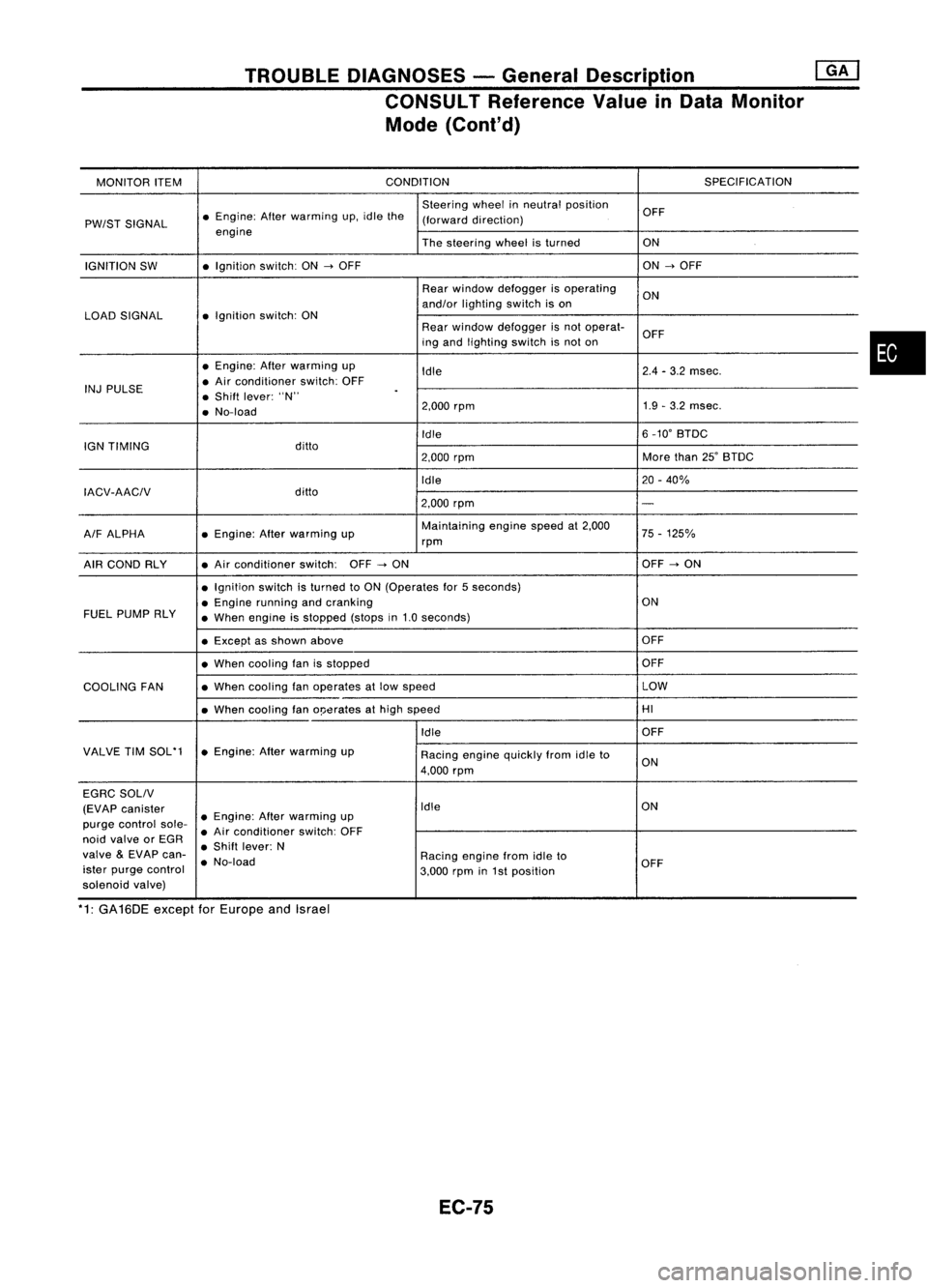
TROUBLEDIAGNOSES -General Description @KJ
CONSULT Reference ValueinData Monitor
Mode (Cont'd)
MONITOR ITEM CONDITION
SPECIFICATION
Steering wheelinneutral position
OFF
PW/ST SIGNAL •
Engine: Afterwarming up.idle the
(forward direction)
engine Thesteering wheelisturned ON
IGNITION SW •
Ignition switch:ON
-->
OFF ON
-->
OFF
Rear window defogger isoperating
ON
and/or lighting switchison
LOAD SIGNAL •
Ignition switch:ON
Rearwindow defogger isnot operat-
OFF
ing and lighting switchisnot on
• Engine: Afterwarming up
Idle 2.4
-3.2 msec.
INJ PULSE •
Air conditioner switch:OFF
• Shift lever: "N"
.
• No-load 2.000
rpm 1.9
-3.2 msec.
Idle 6
_10' BTDC
IGN TIMING ditto
2.000rpm More
than25'BTDC
Idle 20-40%
IACV-AACIV ditto
2.000rpm
-
A/F ALPHA •
Engine: Afterwarming up Maintaining
enginespeedat2.000
75-125%
rpm
AIR COND RLY •
Air conditioner switch:OFF
-->
ON OFF
-->
ON
• Ignition switchisturned toON (Operates for5seconds)
• Engine running andcranking ON
FUEL PUMP RLY
•When engine isstopped (stopsin1.0 seconds)
• Except asshown above OFF
• When cooling fanisstopped OFF
COOLING FAN •
When cooling fanoperates atlow speed LOW
• When cooling fano!Jerates athigh speed HI
Idle OFF
VALVE TIMSOL'1 •Engine: Afterwarming up
Racingenginequickly fromidleto
4.000 rpm ON
EGRC SOLIV
(EVAP canister Idle
ON
purge control sole-•
Engine: Afterwarming up
• Air conditioner switch:OFF
noid valve orEGR
•Shift lever: N
valve
&
EVAP can-
•No-load Racing
enginefromidleto
ister purge control
3.000rpmin1st position OFF
solenoid valve)
*1: GA16DE exceptforEurope andIsrael
EC-75
•
Page 799 of 1701
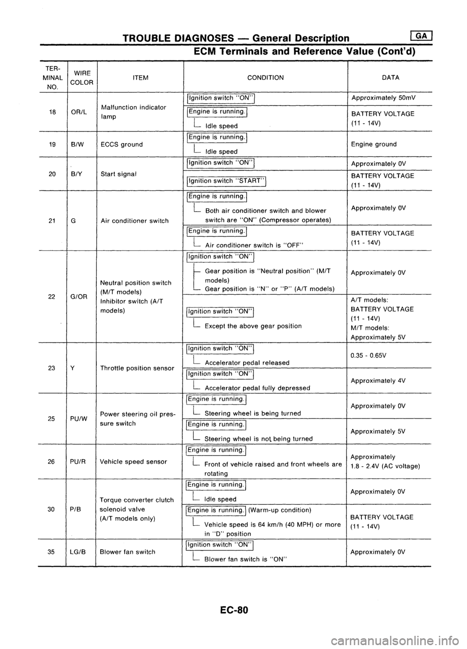
TROUBLEDIAGNOSES -General Description ~
ECM Terminals andReference Value(Cont'd)
TER- WIRE
MINAl ITEM CONDITION DATA
NO. COLOR
/'gnitionswitch"ON'" Approximately
50mV
18 OR/l Malfunction
indicator
I
Engine isrunning.
I
lamp BATTERY
VOLTAGE
L
Idle speed (11.14V)
19 BIW ECCS
ground
I
Engine isrunning.
I
Engineground
L
Idle speed
I'gnition switch"ON"
I
ApproximatelyOV
20 BIY
Startsignal
BATTERYVOLTAGE
I'gnition switch"5TART"
I
(11-14V)
I
Engine isrunning.
I
L
Both airconditioner switchandblower Approximately
OV
21 G Airconditioner switch switch
are"ON" (Compressor operates)
IEngine isrunning.
I
BATTERYVOLTAGE
L
Airconditioner switchis"OFF" (11
-14V)
I'gnition switch"ON'"
t
Ge.,
po,"'on "
"Ne"".1
po,ltlon"
(MIT
Approximately OV
Neutral position switch models)
(M/T
models) Gear
position is"N" or"P"
(A/T
models)
22
G/OR
Inhibitorswitch
(A/T AIT
models:
models) llgnitionswitch"ON'" BATTERY
VOLTAGE
L
Except theabove gearposition (11
-14V)
M/T
models:
Approximately 5V
Ilgnition switch"ON"
I
0.35-0.65V
L
Accelerator pedalreleased
23 Y Throttleposition sensor
!'gnitionswitch"ON"
I
L
Accelerator pedalfullydepressed Approximately
4V
/Engine isrunning.1
ApproximatelyOV
25 Pu/W Power
steering oilpres-
L
Steering wheelisbeing turned
sure switch
IEngineisrunning.1
L
Steering wheelisnot being turned Approximately
5V
I
Engine isrunning.
I
Approximately
26 PUIR Vehiclespeedsensor
L
Front ofvehicle raisedandfront wheels are
1.8-2.4V (ACvoltage)
rotating
I
Engine isrunning.
I
ApproximatelyOV
Torque converter clutch
L
Idle speed
30 PIB
solenoidvalve
I
Engine isrunning.
I
(Warm-up condition)
(A/T
models only)
L
Vehicle speedis64 km/h (40MPH) ormore BATTERY
VOLTAGE
(11-14V)
in "D" position
35 lG/B Blower
fanswitch I,gnition
switch"ON",
ApproximatelyOV
L
Blower fanswitch is"ON"
EC-80
Page 804 of 1701
![NISSAN ALMERA N15 1995 Service Manual TROUBLEDIAGNOSES -General Description @K]
ECM Terminals andReference Value(Conl'd)
TERMINAL WIRE
NO. COLOR ITEM
CONDITION
DATA
Ilgnition switch"ON"I
ApproximatelyOV
34 BIY Startsignal
pgn NISSAN ALMERA N15 1995 Service Manual TROUBLEDIAGNOSES -General Description @K]
ECM Terminals andReference Value(Conl'd)
TERMINAL WIRE
NO. COLOR ITEM
CONDITION
DATA
Ilgnition switch"ON"I
ApproximatelyOV
34 BIY Startsignal
pgn](/manual-img/5/57349/w960_57349-803.png)
TROUBLEDIAGNOSES -General Description @K]
ECM Terminals andReference Value(Conl'd)
TERMINAL WIRE
NO. COLOR ITEM
CONDITION
DATA
Ilgnition switch"ON"I
ApproximatelyOV
34 BIY Startsignal
pgnitionswitch"START"I BATTERY
VOLTAGE
(11 -14V)
pgnition switch"ON"I
t
"N" or"P" position
(A/T)
OV
Neutral position
(M/T)
Neutral position switchl For
Europe andIsrael
35
G/OR
Approximately5V
Inhibitor switch
llgnitionswitch"ON"1
ExceptforEurope and
. L
Except theabove gearposition Israel
BATTERY VOLTAGE
(11 -14V)
Ilgnition switch"OFF"!
OV
36 B/R Ignition
switch(Except
for Europe)
!Ignitionswitch"ON"I BA
TTERY VOLTAGE
(11 •14V)
37 P/L Throttle
position sensor
Ilgnitionswitch"ON"I
Approximately5V
power supply
38
W/R
Powersupply forECM Ilgnition switch"ON"I BA
TTERY VOLTAGE
47 (11
-14V)
IEngine isrunning.1
L
Both airconditioner switchandblower Approximately
OV
41 Gor GY Air
conditioner switch fan
switch are"ON".
!Engine isrunning.1
BATTERYVOLTAGE
L
Airconditioner switchis"OFF". (11
-14V)
IEngine isrunning.!
OV
PU/W Power
steering oilpres-
L
Steering wheelisbeing turned.
43 sureswitch
IEngineisrunning.1
L
Steering wheelisnot being turned. Approximately
5V
jlgnition switch"OFF"I OV
Ignition switch
44 B/R
(ForEurope) BA
TTERY VOLTAGE
pgnition switch"ON"I
(11-14V)
IEngine isrunning.1
Thermo controlamp.
L
Both airconditioner switchandblower fanApproximately
OV
44 R/L (Except
forEurope and switch
are"ON".
Israel) IEngineisrunning.1
BATTERYVOLTAGE
L
Airconditioner switchis"OFF". (11
-14V)
IEngine isrunning.1
ApproximatelyOV
L
Blower fanswitch is"ON".
45 LG/B
or
Blower fanswitch
G/Y
IEngineisrunning.!
L
Blower fanswitch is"OFF". Approximately
5V
EC-85
•
Page 824 of 1701
•
Repair
harness orcon-
nectors.
Repair harness orcon-
nectors.
Replace massairflow
sensor. Repair
harness orcon-
nectors.
NG
NG
NG
NG
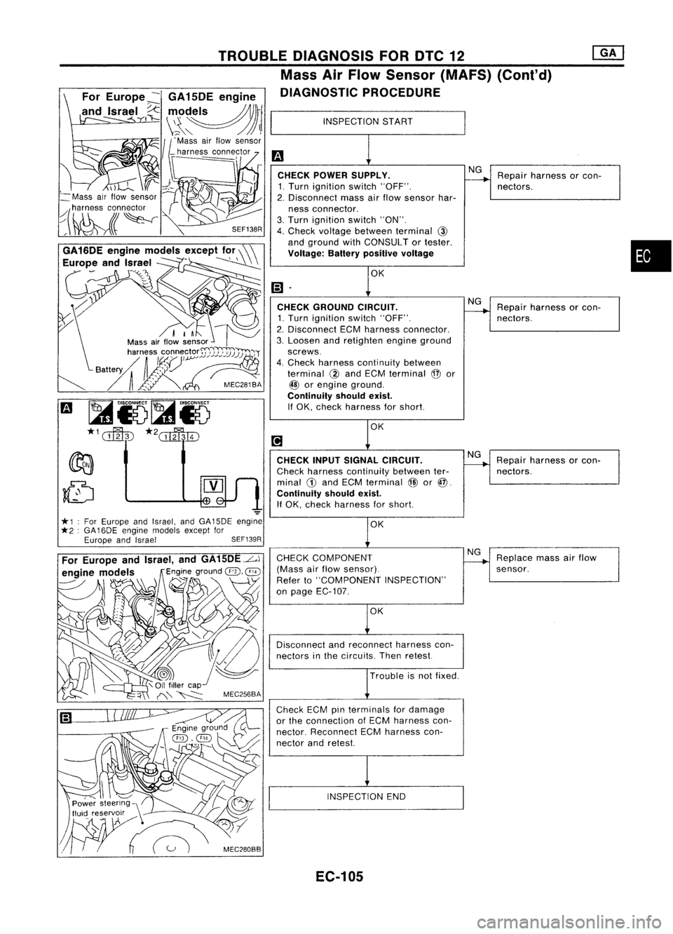
INSPECTION
START
CHECK POWER SUPPLY.
1. Turn ignition switch"OFF".
2. Disconnect massairflow sensor har-
ness connector.
3. Turn ignition switch"ON".
4. Check voltage between terminal
@
and ground withCONSULT ortester.
Voltage: Batterypositive voltage
CHECK INPUTSIGNAL CIRCUIT.
Check harness continuity betweenter-
minal
CD
and ECM terminal
@
or@.
Continuity shouldexist.
If OK, check harness forshort.
INSPECTION END
OK
Trouble isnot fixed.
CHECK
GROUND CIRCUIT.
1. Turn ignition switch"OFF".
2. Disconnect ECMharness connector.
3. Loosen andretighten engineground
screws.
4. Check harness continuity between
terminal
@
and ECM terminal
@
or
@
orengine ground.
Continuity shouldexist.
If OK, check harness forshort.
CHECK COMPONENT
(Mass airflow sensor).
Refer to"COMPONENT INSPECTION"
on page EC-107.
Disconnect andreconnect harnesscon-
nectors inthe circuits. Thenretest.
Check ECMpinterminals fordamage
or the connection ofECM harness con-
nector. Reconnect ECMharness con-
nector andretest.
SEF138R
TROUBLE
DIAGNOSIS FORDTC12
Mass AirFlow Sensor (MAFS) (Conl'd)
DIAGNOSTIC PROCEDURE
For Europe ~GA 15DE engine
and Israel
I~
",,~~)rl
\~\" /JJ~
11'
Mass airflow sensor
_ harness connector
==---,
I-
I
I
d.-
I
;~
*1 ForEurope andIsrael, andGA15DE engine
*2 :GA 16DE engine models exceptfor
Europe andIsrael SEF139R
~
Mass airflow sensor
~(~lr~~
,~\ C/
Power steering \'
tluic! reservxr ..--\ /,'"
W~
Meo,"""
EC-105
Page 850 of 1701
•
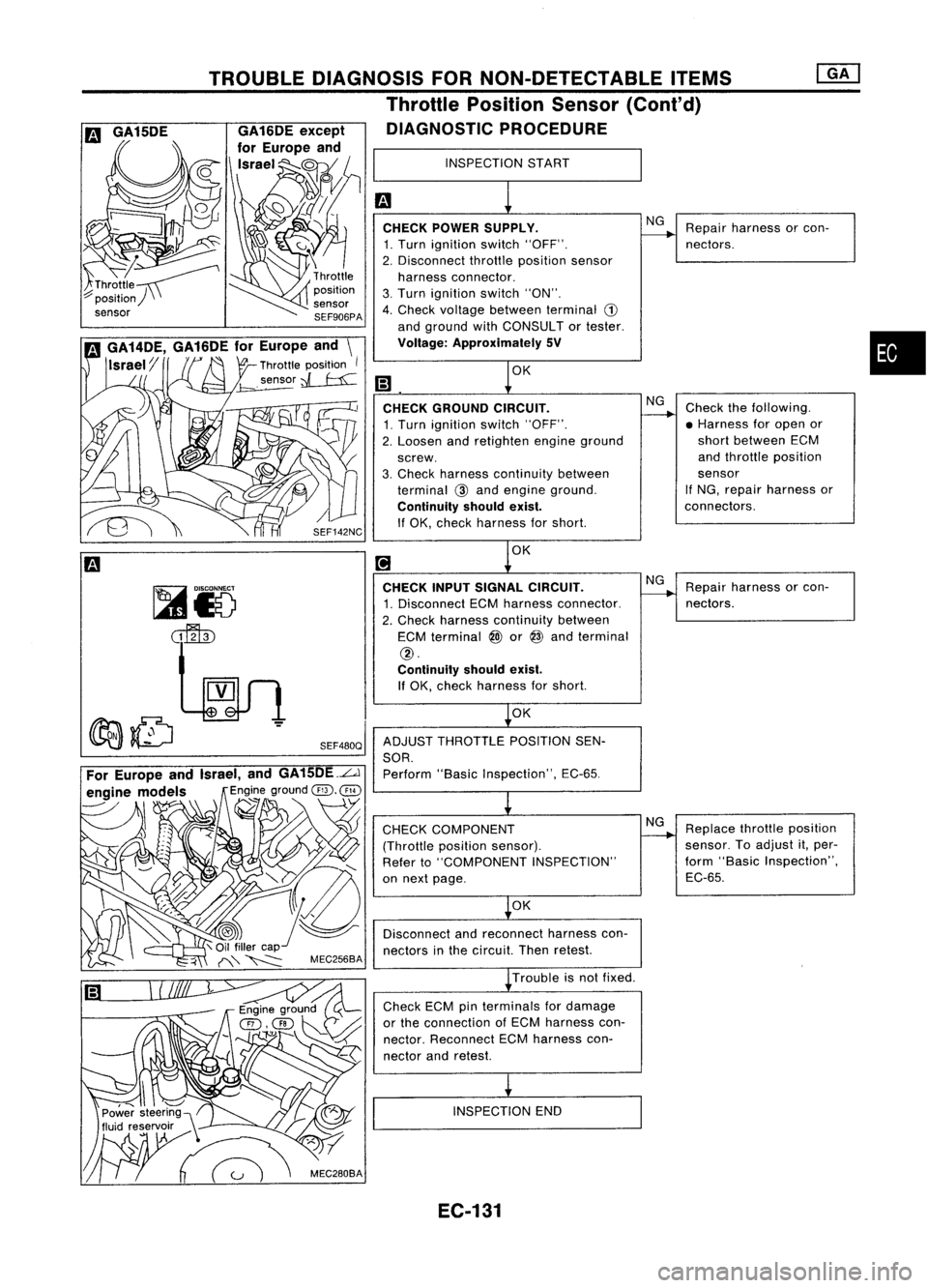
INSPECTION
START
m
1
CHECK POWER SUPPLY.
NG
Repair harness orcon-
------.
1. Turn ignition switch"OFF". nectors.
2. Disconnect throttleposition sensor
harness connector.
3. Turn ignition switch"ON".
4. Check voltage between terminal
CD
and ground withCONSULTor tester.
Voltage: Approximately SV
m
1
0K
CHECK GROUND CIRCUIT.
NG
Check thefollowing.
1. Turn ignition switch"OFF".
------.
•Harness foropen or
2. Loosen andretighten engineground short
between ECM
screw. and
throttle position
3. Check harness continuity between sensor
terminal
@
and engine ground. If
NG, repair harness or
Continuity shouldexist.
connectors.
If OK, check harness forshort.
[!J
1
0K
CHECK INPUTSIGNAL CIRCUIT.
NG
Repair harness orcon-
1. Disconnect ECMharness connector.
------.
nectors.
2. Check harness continuity between
ECM terminal
@)
or
@
and terminal
@.
Continuity shouldexist.
If OK, check harness forshort.
~OK
ADJUST THROTTLE POSITIONSEN-
SOR. Perform "BasicInspection", EC-65.
~
CHECK COMPONENT NG
Replace throttleposition
(Throttle positionsensor).
------.
sensor. Toadjust it,per-
Refer to"COMPONENT INSPECTION" form
"Basic Inspection",
on next page. EC-65.
~OK
Disconnect andreconnect harnesscon-
nectors inthe circuit. Thenretest.
~ Trouble isnot fixed.
Check ECMpinterminals fordamage
or the connection ofECM harness con-
nector. Reconnect ECMharness con-
nector andretest.
i
INSPECTION END
SEF480Q
TROUBLE
DIAGNOSIS FORNON-DETECTABLE ITEMS
Throttle Position Sensor(Cont'd)
DIAGNOSTIC PROCEDURE
,~\ C/
Power steering)\
~
m
GA15DE
EC-131
Page 869 of 1701
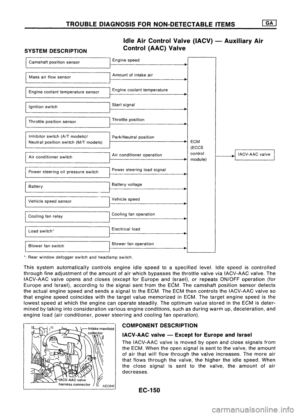
TROUBLEDIAGNOSIS FORNON-DETECTABLE ITEMS
SYSTEM DESCRIPTION Idle
AirControl Valve(IACV) -Auxiliary Air
Control (AAC)Valve
Camshaft positionsensor Engine
speed
I
Mass
airflow sensor Amount
ofintake air
I
Engine coolant temperature sensor Engine
coolant temperature
~
I
Ignition switch Start
signal
I
Throttle positionsensor Throttle
position
~
I
Inhibitor switch(A/Tmodels)/
Park/Neutralposition
Neutral position switch(M/Tmodels) ECM
(ECCS
Air conditioner operation control
!
IACV-AAC valve
I
Air conditioner switch
module)
Power steering oilpressure switch Power
steering loadsignal
I
Battery
~
Battery voltage
Vehicle speedsensor Vehicle
speed
Cooling fanrelay Cooling
fanoperation
Load switch' Electrical
load
Blower fanswitch Blower
fanoperation
': Rear window defogger switchandheadlamp switch.
This system automatically controlsengineidlespeed toaspecified level.Idlespeed iscontrolled
through fineadjustment ofthe amount ofair which bypasses thethrottle valveviaIACV-AAC valve.The
IACV-AAC valveopens andcloses (except forEurope andIsrael), orrepeats ON/OFF operation (for
Europe andIsrael), according tothe signal sentfrom theECM. Thecamshaft positionsensordetects
the actual engine speedandsends asignal tothe ECM. TheECM thencontrols theIACV-AAC valveso
that engine speedcoincides withthetarget valuememorized inECM. Thetarget engine speedisthe
lowest speedatwhich theengine canoperate steadily. Theoptimum valuestored inthe ECM isdeter-
mined bytaking intoconsideration variousengineconditions, suchasduring warmup,deceleration, and
engine load(airconditioner, powersteering andcooling fanoperation).
COMPONENT DESCRIPTION
IACV-AAC valve-Except forEurope andIsrael
The IACV-AAC valveismoved byopen andclose signals from
the ECM. When theopen signal issent tothe valve, theamount
of air that willflow through thevalve increases. Themore air
that flows through thevalve, thehigher theidle speed. When
the close signal issent tothe valve. theamount ofair
decreases.
EC-150
Page 888 of 1701
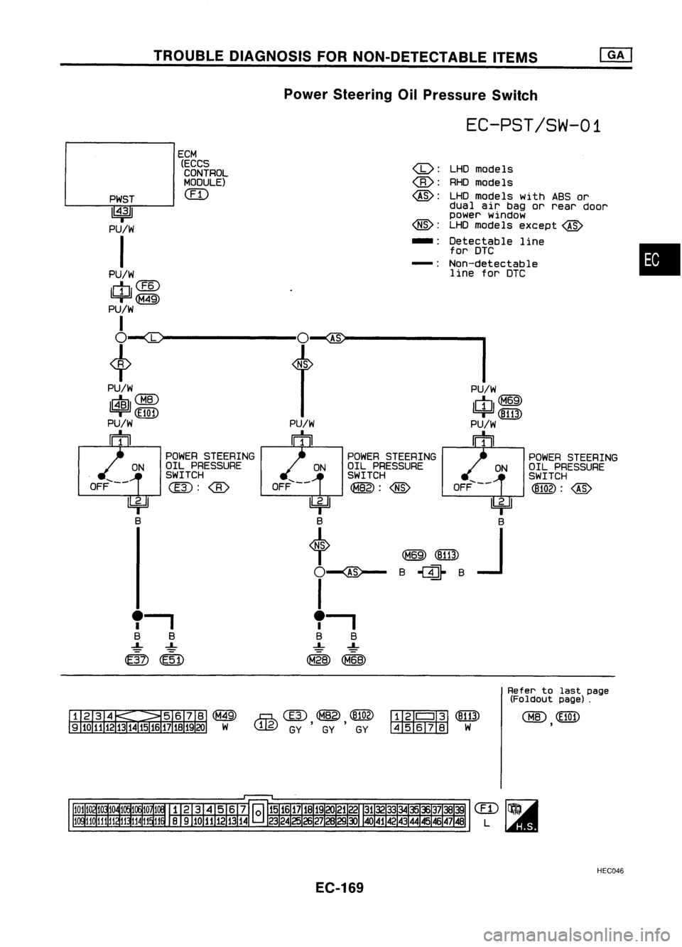
TROUBLEDIAGNOSIS FORNON-DETECTABLE ITEMS
Power Steering OilPressure Switch
EC-PST/SW-01
•
LHD
models
RHO models
LHD models withABSor
dual airbag orrear door
power window
LHO models except
@
Detectable line
for DTC
Non-detectable line forDTC
(0:
@:
@:
-:
-:
ECM
(ECCSCONTROL
MODULE)
em
PWST
1~31
PU/W
I
PU/W
14J1
PU/W
I
+~--------~'-@--------I
PU/W PU/W
1$11
CHID
1c}J1~
(El0n (8113)
PU/W PU/W
rh rh
,.
B B
~ ~
m
(E51)
POWER
STEERING
OIL PRESSURE
SWITCH
~:
STEERING
OIL PRESSURE
SWITCH
(8102):
@
ON
OFF .....--
~B
J
ON
OFF .....--
~B
+
O~
I
,.
B B
~ ~
@~
POWER
STEERING
OIL PRESSURE
SWITCH
@:@
ON
~ B
~
W
,..Q...
@ ~
(8102)
UJ.g)
GY,GY ,GY
ffiIl'
I
lfij
(8113)
45678 W
Refer
tolast page
(Foldout page).
CHID
(El0n
,
HEC046
EC-169
Page 889 of 1701
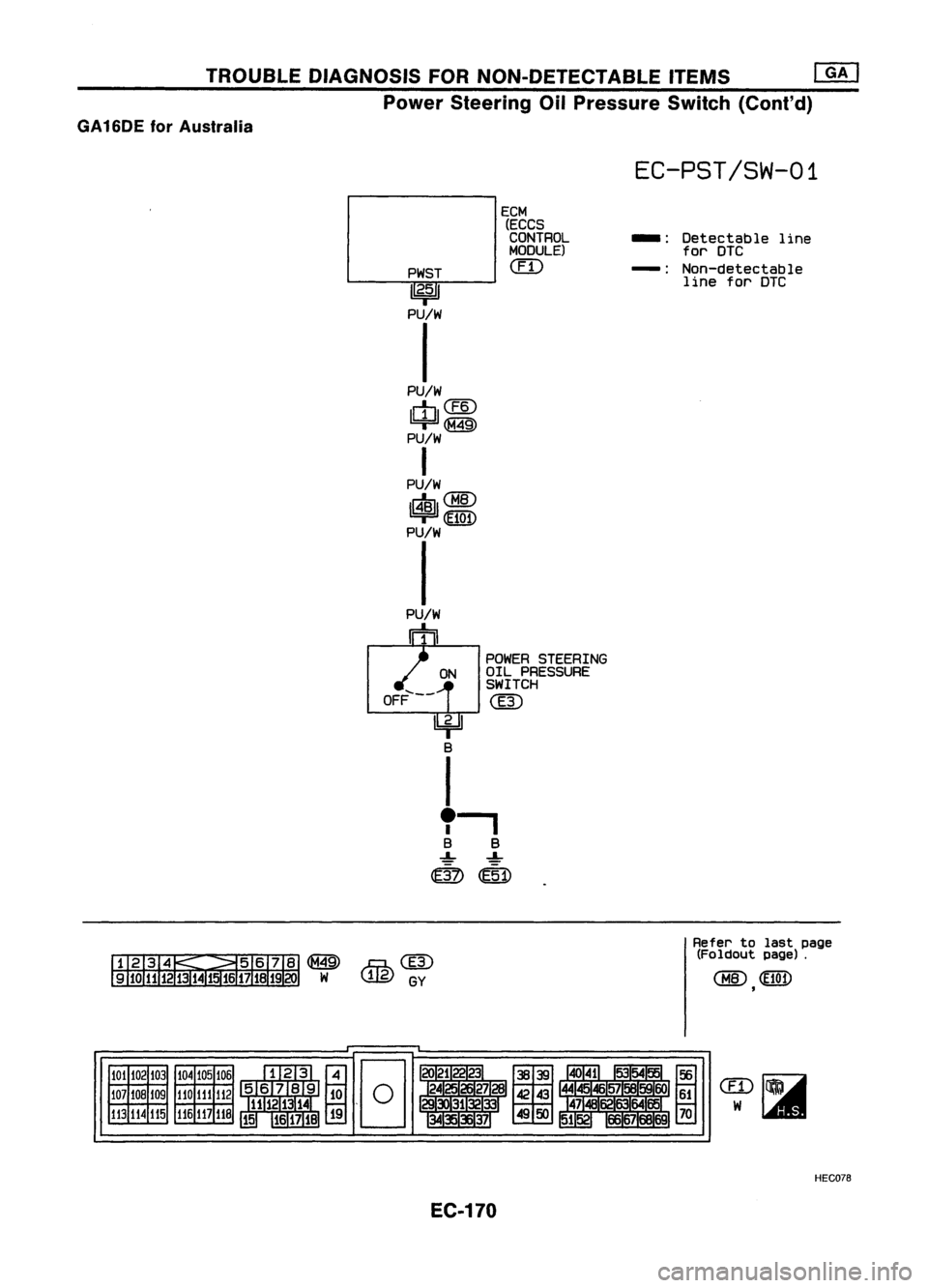
TROUBLEDIAGNOSIS FORNON-DETECTABLE ITEMS
@J
Power Steering OilPressure Switch(Cont'd)
GA16DE forAustralia
EC-PST/SW-01
PWST
1
2•5
1
PU/W
I
PU/W
Iml@
=r~
PU/W
I
PU/W
1$11
~
PU/W
I
ECM
(ECCS
CONTROL
MODULE)
(IT)
-:
Detectable line
for
DTC
-: Non-detectable
line for
DTC
POWER STEERING
OIL PRESSURE
SWITCH
@
ON
OFF'---
~B
I
,-,
B B
..L. ..L.
do
~1)
~@
W,g)
GY
Refer
tolast page
(Foldout page).
,
101 102103
107 108109
113 114
115 104
105
106
110 111112
116
117
118
EC.170 HEC078