Page 994 of 1701

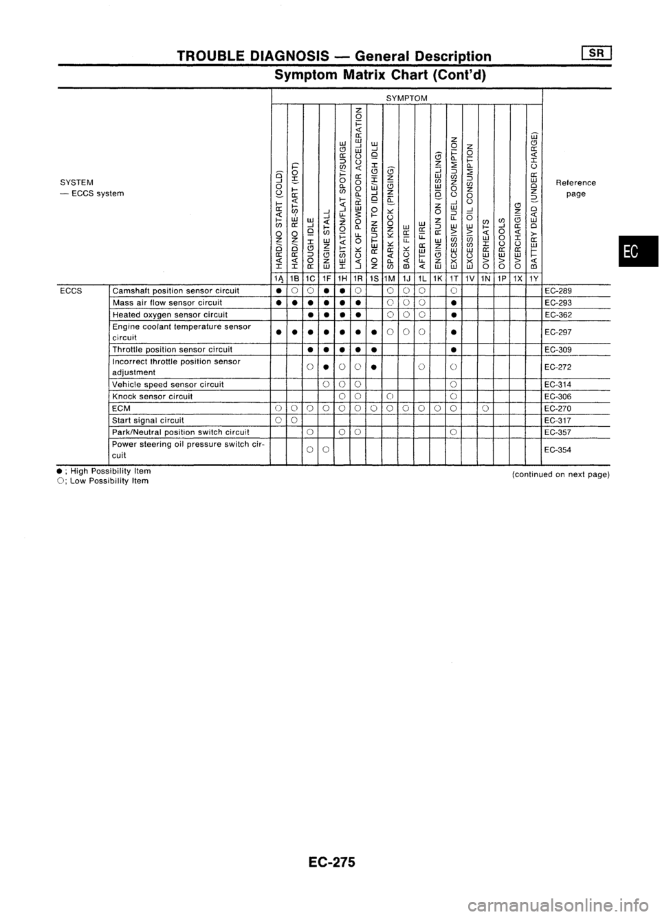
TROUBLEDIAGNOSIS -General Description
Symptom MatrixChart(Cont'd)
SYMPTOM
z
0
1=
0::
Z
W
w w
CJ
..J
W
0
Z
CJ
W
..J
1=
0
0::
0::
()
9
5
Q.
1=
::::>
()
z
:2
I
i='
en
I
5
::;
Q.
()
is'
0
;:::
CJ
::::>
:2
0::
~
0::
:r:
z
w
en
::::>
SYSTEM
..J
0
0
en
z
w
Reference
0
Q.
W
e;
w
en
0
- ECCS system
~
....
en
0
..J
Z
9-
0
z
Z
0::
Q.
9
a:
()
0
2-
page
....
....
ii:
..J
U
....
Z
CJ
0::
..J
W
0
W
..J
0
en
..J
u-
s:
.... ::.:::
0
::::>
0
z
W
..J
U
u-
e;
....
w
Z
0
z
0
w
z
(/)
en
w
en
0::
..J
....
Q.
W
::::>
w
w
....
..J
0::
0
0 0
9
en
0
0::
Z
0::0::
0::
>>
0
>-
~
u-
::::>::.:::
u:
enen
0
I
Z Z
W
0
....
u:
w
W
0::
2i 2i
I
Z
W
::.:::
0::
z
en
(/)
I
()
()
w
CJ
e;
....
::.:::
0:: 0::
::.:::
w w
W
0::
0::
0::
1=
0::
0::
::::>
en
()
()
....
e;
uu
w
w
w
0
Z
w
0
Q.
u-
Z
x x
> >>
I I
0::
W
I
..J
Z
(/)
1Il
w
w w
000
1Il
11\ 18
1C 1F
1H 1R
1S1M 1J1L1K
1T
1V1N 1P1X
1Y
ECCS Camshaft
positionsensorcircuit
•
0
0
••
0
000 0
EC-289
Mass airflow sensor circuit
•••
•••
0
00
•
EC-293
Heated oxygen sensorcircuit
••
••
0
00
•
EC-362
Engine coolant temperature sensor
••• ••
•
•
0
0
0
•
EC-297
circuit
Throttle positionsensorcircuit
••
••
• •
EC-309
Incorrect fhrottleposition sensor
0
•
0
0
•
0
0
EC-272
adjustment
Vehicle speedsensor circuit
000
0
EC-314
Knock sensor circuit
00
0 0
EC-306
ECM
0
0
0
0
00000
0
00 0
EC-270
Start signal circuit
00
EC-317
Park/Neutral positionswitchcircuit
000
0
EC-357
Power steering oilpressure switchcir-
0
0
EC-354
cuit
•
• ;High Possibility Item
0;
Low Possibility Item
EC-275
(continued
onnext page)
Page 997 of 1701
![NISSAN ALMERA N15 1995 Service Manual TROUBLEDIAGNOSIS -General Description
[]K]
CONSULT Reference ValueinData Monitor
Mode (Cont'd)
MONITOR ITEM
CONDITION SPECIFICATION
Steering wheelinneutral
position OFF
PW/ST SIGNAL
•Engine: NISSAN ALMERA N15 1995 Service Manual TROUBLEDIAGNOSIS -General Description
[]K]
CONSULT Reference ValueinData Monitor
Mode (Cont'd)
MONITOR ITEM
CONDITION SPECIFICATION
Steering wheelinneutral
position OFF
PW/ST SIGNAL
•Engine:](/manual-img/5/57349/w960_57349-996.png)
TROUBLEDIAGNOSIS -General Description
[]K]
CONSULT Reference ValueinData Monitor
Mode (Cont'd)
MONITOR ITEM
CONDITION SPECIFICATION
Steering wheelinneutral
position OFF
PW/ST SIGNAL
•Engine: Afterwarming up,idle theengine (forward
direction)
The steering wheelis
ON
turned
• Engine: Afterwarming up
Idle2.5-3.7 msec .
INJ PULSE •
Air conditioner switch:OFF
• Shift lever: "N"
• No-load 2,000
rpm 1.9-2.8 msec .
Idle 13-15° BTDC
IGN TIMING
ditto
2,000rpm Morethan25°BTDC
Idle 20-40%
IACV-AACIV ditto
2,000rpm
-
A/F ALPHA •Engine: Afterwarming up Maintaining
enginespeed
53-155%
at 2.000 rpm
AIR COND RLY •Air conditioner switch:OFF
-+
ON OFF
-+
ON
• Ignition switchis~urned toON (Operates for5seconds)
• Engine running andcranking ON
FUEL PUMP RLY
•When engine isstopped (stopsin1.0 seconds)
• Except asshown above OFF
Engine coolant temperature
is 94°C (201°F) orless for
AfT models. and99°C OFF
(210°F) orless for
M/T
mod-
els
• After warming upengine. idletheengine. Engine
coolant temperature
is between 95°C(203°F) and
COOLING FAN •Air conditioner switch:OFF
104°C(219°F) forA/T mod- LOW
• Vehicle stopped
elsonly
Engine coolant temperature
is 105°C (221°F) ormore for
A/T
models. and100°C HIGH
(212°F) ormore for
M/T
models
• Engine: Afterwarming up
IdleON
EGRC SOLIV •
Air conditioner switch:OFF
• Shift lever: "N"
• No-load 2.000
rpm OFF
EC-278
Page 1003 of 1701
![NISSAN ALMERA N15 1995 Service Manual TROUBLEDIAGNOSIS -General Description
[]:KJ
ECM Terminals andReference Value(Cont'd)
*Data arereference values.
TERMINAL WIRE
ITEM CONDITION *
DATA
NO. COLOR
/Ignitionswitch"ON'"
t NISSAN ALMERA N15 1995 Service Manual TROUBLEDIAGNOSIS -General Description
[]:KJ
ECM Terminals andReference Value(Cont'd)
*Data arereference values.
TERMINAL WIRE
ITEM CONDITION *
DATA
NO. COLOR
/Ignitionswitch"ON'"
t](/manual-img/5/57349/w960_57349-1002.png)
TROUBLEDIAGNOSIS -General Description
[]:KJ
ECM Terminals andReference Value(Cont'd)
*Data arereference values.
TERMINAL WIRE
ITEM CONDITION *
DATA
NO. COLOR
/Ignitionswitch"ON'"
t
"N" or"P" position
(A/T)
OV
35
G/OR
Neutral
position
Neutralposition
(M/T)
switch/lnhibitor switch
I'gnitionswitch"ON"I
BATTERYVOLTAGE
L
Except theabove gearposition (11
-14V)
I'gnition switch"OFF"I
OV
36 B/R Ignition
switch
Ilgnitionswitch"ON"I BATTERY
VOLTAGE
(11 -14V)
37 P/L Throttle
position sen-
pgnition switch"ON"I
Approximately5V
sor power supply
38 Powersupply forECM
Ilgnition switch"ON"I BATTERY
VOLTAGE
47 W/R
(11-14V)
39 B ECCSground IEngine
isrunning.1
Engineground
L
Idle speed
IEngine isrunning.!
L
Both airconditioner switchandblower fanApproximately
OV
41 G Air
conditioner switch switch
are"ON".
IEngine isrunning.1
BATTERYVOLTAGE
L
Airconditioner switchis"OFF". (11
-14V)
IEngine isrunning.1
OV
Power steering oil
L
Steering wheelisbeing turned.
43 PUlW
pressureswitch
IEngineisrunning.1
L
Steering wheelisnot being turned. 7
-9V
46 W/L Power
supply
I'gnitionswitch
"0FFj
BATTERY
VOLTAGE
(Back-up) (11-14V)
48 B ECCSground IEngine
isrunning.1
Engineground
L
Idle speed
109 W/L Currentreturn
Ilgnitionswitch"OFF"I BATTERY
VOLTAGE
(11 -14V)
101 RIB InjectorNo.1
103
G/B
InjectorNo.3
BATTERYVOLTAGE
110 Y/B InjectorNO.2 IEngine
isrunning.1
(11-14V)
112 LIB InjectorNO.4
EC-284
Page 1054 of 1701

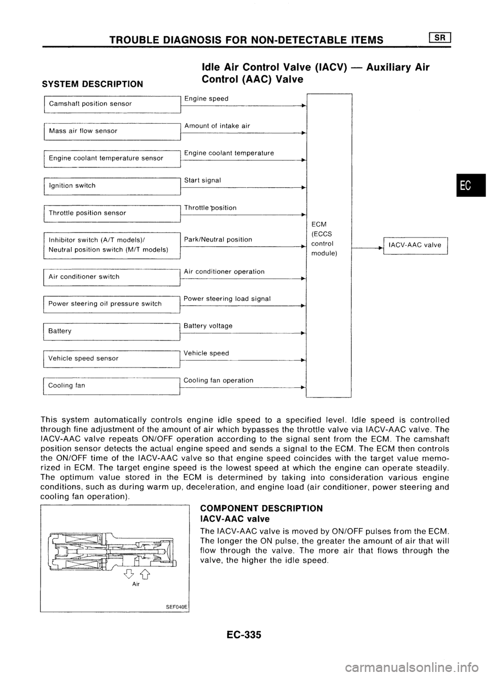
TROUBLEDIAGNOSIS FORNON-DETECTABLE ITEMS
SYSTEM DESCRIPTION Idle
AirControl Valve(IACV) -Auxiliary Air
Control (AAC)Valve
Camshaft positionsensor Engine
speed
~
I
Amount ofintake air
Mass airflow sensor
I
Engine coolant temperature sensor Engine
coolant temperature
I
Ignition switch Start
signal
I
Throttle position sensor Throttle
"position
I
ECM
Inhibitor switch(A/Tmodels)/ Park/Neutral
position (ECCS
control
!
IACV-AAC valve
I
Neutral position switch(M/Tmodels)
module)
Air conditioner switch Air
conditioner operation
Power steering oilpressure switch Power
steering loadsignal
I
Battery Battery
voltage
Vehicle speedsensor Vehicle
speed
I
l
Cooling fan Cooling
fanoperation
I
This system automatically controlsengineidlespeed toaspecified level.Idlespeed iscontrolled
through fineadjustment ofthe amount ofair which bypasses thethrottle valveviaIACV-AAC valve.The
IACV-AAC valverepeats ON/OFF operation according tothe signal sentfrom theECM. Thecamshaft
position sensordetects theactual engine speedandsends asignal tothe ECM. TheECM thencontrols
the ON/OFF timeofthe IACV-AAC valvesothat engine speedcoincides withthetarget valuememo-
rized inECM. Thetarget engine speedisthe lowest speedatwhich theengine canoperate steadily.
The optimum valuestored inthe ECM isdetermined bytaking intoconsideration variousengine
conditions, suchasduring warmup,deceleration, andengine load(airconditioner, powersteering and
cooling fanoperation).
COMPONENTDESCRIPTION
IACV-AAC valve
The IACV-AAC valveismoved byON/OFF pulsesfromtheECM.
The longer theONpulse, thegreater theamount ofair that will
flow through thevalve. Themore airthat flows through the
valve, thehigher theidle speed.
Air SEF040E
EC-335
•
Page 1073 of 1701
TROUBLEDIAGNOSIS FORNON-DETECTABLE ITEMS~
Power Steering OilPressure Switch
EC-PST/SW-01
PWST
1~31
PU/W
I
PU/W
Irnl
CfID
=r@
PU/W
I
PU/W
I$J'CMID
~
pu/w
I
ECM
(ECCS
CONTROL
MODULE)
em
-:
Detectable line
for DTC
-: Non-detectable
line for
DTC
POWER STEERING
OIL PRESSURE
SWITCH
(g)
ON
OFF .....--
~B
I
,-,
B B
-L -L
@
<1;51)
~@
U@
GY
Refer
tolast page
(Foldout page).
CHID
m
,
em
L
EC-354 HEC018
Page 1074 of 1701

MEC730B
•
INSPECTION
START
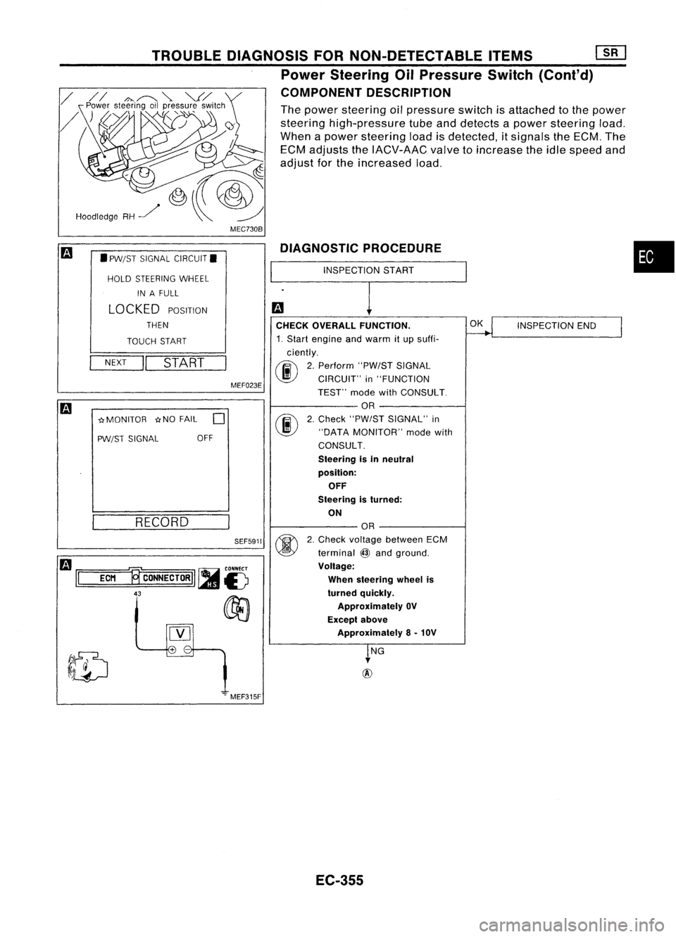
DIAGNOSTIC
PROCEDURE
CHECK OVERALL FUNCTION.
~
INSPECTION
END
I
1. Start engine andwarm itup suffi-
ciently.
00
2.
Perform "PW/STSIGNAL
CIRCUIT" in"FUNCTION
TEST" modewithCONSULT.
OR
@
2.
Check "PW/ST SIGNAL" in
"DATA MONITOR" modewith
CONSULT.
Steering isin neutral
position: OFF
Steering isturned:
ON
OR
@
2.
Check voltage between ECM
terminal
@
and ground.
Voltage:
When steering wheelis
turned quickly.
Approximately OV
Except above
Approximately 8-10V
~NG
+
-
SEF5911
MEF023E
TROUBLE
DIAGNOSIS FORNON-DETECTABLE ITEMS[][]
Power Steering OilPressure Switch(Cont'd)
COMPONENT DESCRIPTION
The power steering oilpressure switchisattached tothe power
steering high-pressure tubeanddetects apower steering load.
When apower steering loadisdetected, itsignals theECM. The
ECM adjusts theIACV-AAC valvetoincrease theidle speed and
adjust forthe increased load.
RECORD
NEXT
II
START
•
PW/ST SIGNAL CIRCUIT.
HOLD STEERING WHEEL
IN AFULL
LOCKED
POSITION
THEN
TOUCH START
-crMONITOR -crNOFAIL
0
PW/ST SIGNAL OFF
Hoodledge
RH~
m
1='
=EC=M
=.,~
CONNECTORII ~
is
43
00
[Y]
.".MEF315F
EC-355
Page 1075 of 1701

TROUBLEDIAGNOSIS FORNON-DETECTABLE ITEMS
mJ
Power Steering OilPressure Switch
(Cont'd)
~i5
dIb
~i5
II
ECM
~CONNECTORII
43 AEC760
SEF501Q
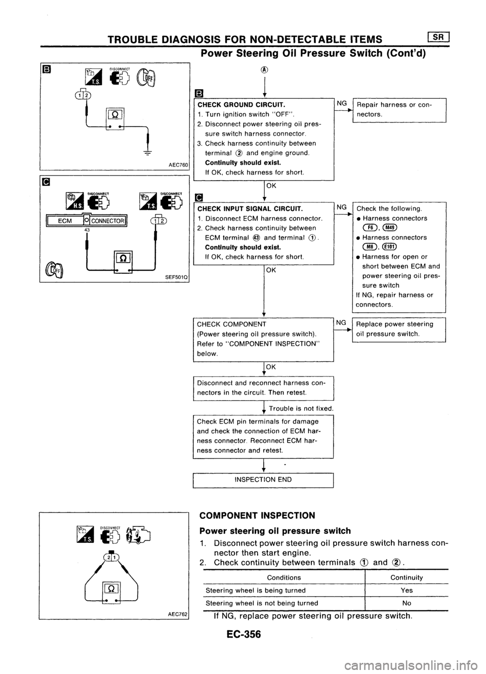
@
1
CHECK GROUND CIRCUIT. NG
Repair harness orcon-
1. Turn ignition switch"OFF".
--..
nectors.
2. Disconnect powersteering oilpres-
sure switch harness connector.
3. Check harness continuity between
terminal
@
and engine ground.
Continuity shouldexist.
If OK, check harness forshort.
OK
[!J
CHECK INPUTSIGNAL CIRCUIT. NG
Check thefollowing.
1. Disconnect ECMharness connector.
--..
•Harness connectors
2. Check harness continuity between
CID,@
ECM terminal
@
and terminal
CD.
•
Harness connectors
Continuity shouldexist.
@,@D
If OK, check harness forshort. •
Harness foropen or
OK short
between ECMand
power steering oilpres-
sure switch
If NG, repair harness or
connectors.
Power steering oilpressure switch
1. Disconnect powersteering oilpressure switchharness con-
nector thenstart engine.
2. Check continuity betweenterminals
CD
and
@.
~
to
ID
~
CHECK
COMPONENT
(Power steering oilpressure switch).
Refer to"COMPONENT INSPECTION"
below.
OK
Disconnect andreconnect harnesscon-
nectors inthe circuit. Thenretest.
Trouble isnot fixed.
Check ECMpinterminals fordamage
and check theconnection ofECM har-
ness connector. ReconnectECMhar-
ness connector andretest.
INSPECTION END
COMPONENT INSPECTION
Conditions
Steering wheelisbeing turned
Steering wheelisnot being turned NG
Replace powersteering
oil pressure switch.
Continuity
Yes
No
AEC762
IfNG, replace powersteering oilpressure switch.
EC-356
Page 1122 of 1701
If
NG, replace powersteering oilpressure switch.
Solenoid
timer
1. Disconnect solenoidtimerharness connector.
2. Apply battery voltage tosolenoid timerterminals andlisten
for operating sound.
•
No
Operating
sound
Yes
Condition
With battery voltage applied
Without batteryvoltage applied
TROUBLE
DIAGNOSES ~
Partial LoadAdvance (PLA)Control (Cont'd)
COMPONENT INSPECTION
Engine speedsensor
1. Disconnect enginespeedsensor harness connector.
2. Check resistance betweenterminals
@
and
CID.
Resistance: Approximately 1.6Q
If
NG, replace fuelpump.
EC-403