1995 NISSAN ALMERA N15 steering
[x] Cancel search: steeringPage 7 of 1701

PREPARATIONANDPRECAUTIONS
Service Notice
Supplemental RestraintSystem(SRS)"AIR
BAG" (DualAirBag System)
The Supplemental RestraintSystem"AirBag" usedalong withaseat belt, helps toreduce therisk or
severity ofinjury tothe driver andfront passenger inafrontal collision. TheSupplemental Restraint
System consists ofair bag modules (locatedinthe center ofthe steering wheelandonthe instrument
panel onthe passenger side),adiagnosis sensorunit,warning lamp,wiring harness andspiral cable.
Information necessarytoservice thesystem safelyisincluded inthe
RSsection
ofthis Service Manual.
WARNING:
• Toavoid rendering theSRS inoperative, whichcouldincrease therisk ofpersonal injuryordeath
in the event ofacollision whichwould resultinair bag inflation, allmaintenance mustbeperformed
by an authorized NISSANdealer.
• Improper maintenance, includingincorrectremovalandinstallation ofthe SRS, canlead topersonal
injury caused byunintentional activationofthe system.
Ii
Donot use electrical testequipment onany circuit related tothe SRS unless instructed tointhis
Service Manual. SRSwiring harnesses arecovered withyellow insulation eitherjustbefore the
harness connectors orfor the complete harness,foreasy identification.
•
Before proceeding withdisassembly, thor-
oughly cleantheoutside ofthe transaxle. Itis
important toprevent theinternal partsfrom
becoming contaminated bydirt orother for-
eign matter.
• Disassembly shouldbedone inaclean work
area.
• Use lint-free clothortowels forwiping parts
clean. Common shopragscanleave fibers
that could interfere withtheoperation ofthe
transaxle.
• Place disassembled partsinorder, onaparts
rack, foreasier andproper assembly.
• Allparts should becarefully cleaned-witha
general purpose, non-flammable solvent
before inspection orreassembly.
• Gaskets, sealsandO-rings shouldbe
replaced anytime thetransaxle isdisassem-
bled.
• Itis very important toperform functional tests
whenever theyareindicated. •
The valve bodycontains precision partsand
requires extremecarewhen partsare
removed andserviced. Placedisassembled
valve bodyparts inorder, onaparts rack,for
easier andproper assembly. Carewillalso
prevent springs andsmall partsfrombecom-
ing scattered orlost.
• Properly installedvales,sleeves, plugs,etc.
will slide along theirbores inthe valve body
under theirownweight.
• Before assembly, applyacoat ofrecom-
mended ATFtoall parts. Apply petroleum
jelly toprotect O-ringandseals, orhold bear-
ings andwashers inplace during assembly.
Do not use grease.
• Extremely careshould betaken toavoid dam-
age toO-rings, sealsandgaskets when
assembling.
• After overhaul, refillthetransaxle withnew
ATF.
•
Supplemental RestraintSystem(SRS)"AIR
BAG" (Single AirBag System)
The Supplemental RestraintSystem"AirBag" andused along withaseat belt,helps toreduce therisk
or severity ofinjury tothe driver inafrontal collision. TheSupplemental RestraintSystemconsists of
an air bag module (located inthe center ofthe steering wheel),adiagnosis sensorunit,warning lamp,
wiring harness andspiral cable. Information necessarytoservice thesystem safelyisincluded inthe
RS section
ofthis Service Manual.
WARNING:
• Toavoid rendering theSRS inoperative, whichcouldincrease therisk ofpersonal injuryordeath
in the event ofacollision whichwould resultinair bag inflation, allmaintenance mustbeperformed
by an authorized NISSANdealer.
• Improper maintenance, includingincorrectremovalandinstallation ofthe SRS, canlead topersonal
injury caused byunintentional activationofthe system.
• Donot use electrical testequipment onany circuit related tothe SRS unless instructed tointhis
Service Manual.
AT-7
Page 222 of 1701

PRECAUTIONS
Service Notice
• When removing orinstalling variousparts,placeacloth orpadding ontothevehicle bodytoprevent
scratches.
• Handle trim,molding, instruments, grille,etc.carefully duringremoving orinstalling. Becareful not
to soil ordamage them.
• Apply sealing compound wherenecessary wheninstalling parts.
• When applying sealingcompound, becareful thatthesealing compound doesnotprotrude from
parts.
• When replacing anymetal parts(forexample bodyouter panel, members, etc.),besure totake rust
prevention measures.
SupplementalRestraintSystem(SRS)"AIR
BAG" (DualAirBag System)
The Supplemental RestraintSystem"AirBag", usedalong withaseat belt,helps toreduce therisk or
severity ofinjury tothe driver andfront passenger inafrontal collision. TheSupplemental Restraint
System consists ofair bag modules (locatedinthe center ofthe steering wheelandonthe instrument
panel onthe passenger side),adiagnosis sensorunit,warning lamp,wiring harness andspiral cable.
Information necessarytoservice thesystem safelyisincluded inthe
RSsection
ofthis Service Manual.
WARNING:
• Toavoid rendering theSRS inoperative, whichcouldincrease therisk ofpersonal injuryordeath
in the event ofacollision whichwould resultinair bag inflation, allmaintenance mustbeperformed
by an authorized NISSANdealer.
• Improper maintenance, includingincorrectremovalandinstallation ofthe SRS, canlead topersonal
injury caused byunintentional activationofthe system.
• Donot use electrical testequipment onany circuit related tothe SRS unless instructed tointhis
Service Manual. SRSwiring harnesses arecovered withyellow insulation eitherjustbefore the
harness connectors orfor the complete harness,foreasy identification.
Supplemental RestraintSystem(SRS)"AIR
BAG" (Single AirBag System)
The Supplemental RestraintSystem"AirBag", usedalong withaseat belt,helps toreduce therisk or
severity ofinjury tothe driver inafrontal collision. TheSupplemental RestraintSystemconsists ofan
air bag module (located inthe center ofthe steering wheel),adiagnosis sensorunit,warning lamp,
wiring harness andspiral cable. Information necessarytoservice thesystem safelyisincluded inthe
RS section
ofthis Service Manual.
WARNING:
• Toavoid rendering theSRS inoperative, whichcouldincrease therisk ofpersonal injuryordeath
in the event ofacollision whichwould resultinair bag inflation, allmaintenance mustbeperformed
by an authorized NISSANdealer.
• Improper maintenance, includingincorrectremovalandinstallation ofthe SRS, canlead topersonal
injury caused byunintentional activationofthe system.
• Donot use electrical testequipment onany circuit related tothe SRS unless instructed tointhis
Service Manual.
BT-2
Page 233 of 1701

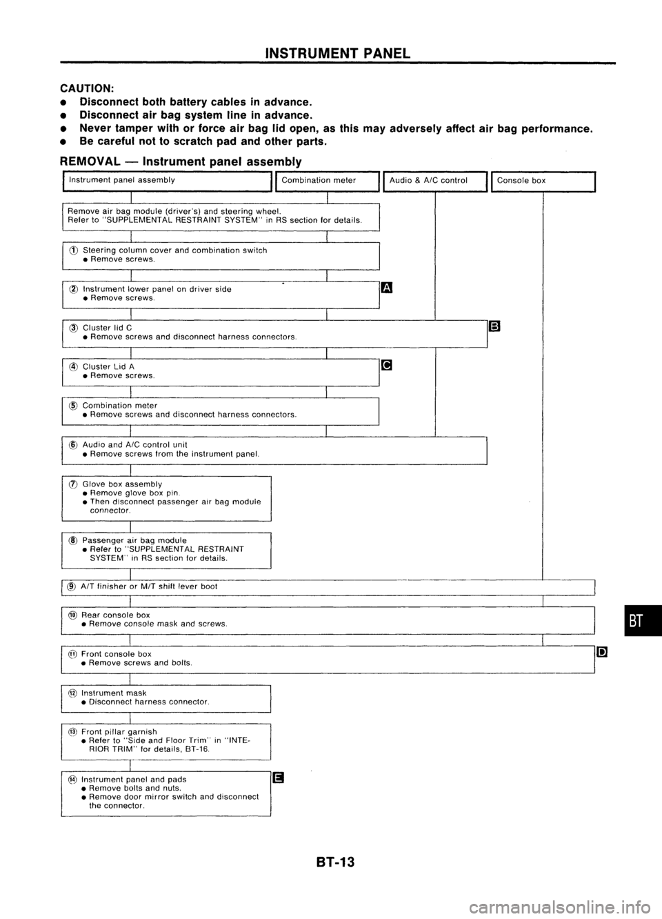
INSTRUMENTPANEL
CAUTION:
• Disconnect bothbattery cablesinadvance.
• Disconnect airbag system lineinadvance.
• Never tamper withorforce airbag lidopen, asthis may adversely affectairbag performance.
• Becareful nottoscratch padandother parts.
REMOVAL -Instrument panelassembly
Instrument panelassembly
Remove airbag module (driver's) andsteering wheel.
Refer to"SUPPLEMENTAL RESTRAINTSYSTEM"inRS section fordetails.
CD
Steering columncoverandcombination switch
• Remove screws.
l6l
Instrument lowerpanel ondriver side
• Remove screws.
@
Cluster lidC
• Remove screwsanddisconnect harnessconnectors. Audio
&AIC
control
Consolebox
@
Cluster lidA
• Remove screws.
@
Combination meter
• Remove screwsanddisconnect harnessconnectors.
cID
Audio and
AIC
control unit
• Remove screwsfromtheinstrument panel.
(J)
Glove boxassembly
• Remove gloveboxpin.
• Then disconnect passengerairbag module
connector.
@
Passenger airbag module
• Refer to"SUPPLEMENTAL RESTRAINT
SYSTEM" inRS section fordetails.
@
AIT
finisher orMIT shift lever boot
@
Rear console box
• Remove consolemaskandscrews.
@
Front console box
• Remove screwsandbolts.
@
Instrument mask
• Disconnect harnessconnector.
@
Front pillargarnish
• Refer to"Side andFloor Trim" in"INTE-
RIOR TRIM" fordetails, 8T-16.
@
Instrument panelandpads
II
• Remove boltsandnuts.
• Remove doormirror switch anddisconnect
the connector.
•
8T-13
Page 273 of 1701

PRECAUTIONSANDPREPARATION
Precautions
SUPPLEMENTAL RESTRAINTSYSTEM(SRS)"AIRBAG"
(DUAL AIRBAG SYSTEM)
The Supplemental RestraintSystem"AirBag" usedalong with
a seat belt,helps toreduce therisk orseverity ofinjury tothe
driver andfront passenger inafrontal collision. TheSupple-
mental Restraint Systemconsists ofair bag modules (located
in the center ofthe steering wheelandonthe instrument panel
on the passenger side),adiagnosis sensorunit,warning lamp,
wiring harness andspiral cable. Information necessarytoser-
vice thesystem safelyisincluded inthe
RSsection
ofthis Ser-
vice Manual.
WARNING:
• Toavoid rendering theSRS inoperatiYe, whichcouldincrease therisk ofpersonal injuryordeath
in the event ofacollision whichwould resultinair bag inflation, allmaintenance mustbeperformed
by an authorized NISSANdealer.
• Improper maintenance, includingincorrectremovalandinstallation ofthe SRS, canlead topersonal
injury caused byunintentional activationofthe system.
• Donot use electrical testequipment onany circuit related tothe SRS unless instructed tointhis
Service Manual. SRSwiring harnesses arecovered withyellow insulation eitherjustbefore the
harness connectors orfor the complete harness,foreasy identification.
SUPPLEMENTAL RESTRAINTSYSTEM(SRS)"AIRBAG"
(SINGLE AIRBAG SYSTEM)
The Supplemental RestraintSystem"AirBag" andused along withaseat belt,helps toreduce therisk
or severity ofinjury tothe driver inafrontal collision. TheSupplemental RestraintSystemconsists of
an air bag module (located inthe center ofthe steering wheel),adiagnosis sensorunit,warning lamp,
wiring harness andspiral cable. Information necessarytoservice thesystem safelyisincluded inthe
RS section
ofthis Service Manual.
WARNING:
• Toavoid rendering theSRS inoperative, whichcouldincrease therisk ofpersonal injuryordeath
in the event ofacollision whichwould resultinair bag inflation, allmaintenance mustbeperformed
by an authorized NISSANdealer.
• Improper maintenance, includingincorrectremovalandinstallation ofthe SRS, canlead topersonal
injury caused byunintentional activationofthe system.
• Donot use electrical testequipment onany circuit related tothe SRS unless instructed tointhis
Service Manual.
BR-3
•
Page 308 of 1701

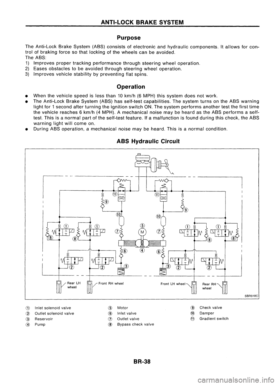
ANTI-LOCKBRAKESYSTEM
Purpose
The Anti-Lock BrakeSystem (ABS)consists ofelectronic andhydraulic components. Itallows forcon-
trol ofbraking forcesothat locking ofthe wheels canbeavoided.
The ABS:
1) Improves propertracking performance throughsteering wheeloperation.
2) Eases obstacles tobe avoided throughsteering wheeloperation.
3) Improves vehiclestability bypreventing flatspins.
Operation
• When thevehicle speedisless than 10km/h (6MPH) thissystem doesnotwork.
• The Anti-Lock BrakeSystem (ABS)hasself-test capabilities. Thesystem turnsonthe ABS warning
light for1second afterturning theignition switchON.The system performs anothertestthefirst time
the vehicle reaches 6km/h (4MPH). Amechanical noisemaybeheard asthe ABS performs aself-
test. This isanormal partofthe self-test feature.Ifa malfunction isfound during thischeck, theABS
warning lightwillcome on.
• During ABSoperation, amechanical noisemaybeheard. Thisisanormal condition.
ABS Hydraulic Circuit
G)
Inletsolenoid valve
@
Outlet solenoid valve
@
Reservoir
@)
Pump
)(
@
@
Motor
@
Inletvalve
(J)
Outlet valve
@ Bypass checkvalve
BR-38 @
Check valve
@)
Damper
@
Gradient switch
SBR918C
Page 376 of 1701

PRECAUTIONS
Supplemental RestraintSystem(SRS)"AIR
BAG" (DualAirBag System)
The Supplemental RestraintSystem"AirBag", usedalong withaseat belt,helps toreduce therisk or
severity ofinjury tothe driver andfront passenger inafrontal collision. TheSupplemental Restraint
System consists ofair bag modules (locatedinthe center ofthe steering wheelandonthe instrument
panel onthe passenger side),adiagnosis sensorunit,warning lamp,wiring harness andspiral cable.
Information necessarytoservice thesystem safelyisincluded inthe
RSsection
ofthis Service Manual.
WARNING:
• Toavoid rendering theSRS inoperative, whichcouldincrease therisk ofpersonal injuryordeath
in the event ofacollision whichwould resultinair bag inflation, allmaintenance mustbeperformed
by an authorized NISSANdealer.
• Improper maintenance, includingincorrectremovalandinstallation ofthe SRS, canlead topersonal
injury caused byunintentional activationofthe system.
• Donot use electrical testequipment onany circuit related tothe SRS unless instructed tointhis
Service Manual. SRSwiring harnesses arecovered withyellow insulation eitherjustbefore the
harness connectors orfor the complete harness,foreasy identification.
Supplemental RestraintSystem(SRS)"AIR
BAG" (Single AirBag System)
The Supplemental RestraintSystem"AirBag", usedalong withaseat belt,helps toreduce therisk or
severity ofinjury tothe driver inafrontal collision. TheSupplemental RestraintSystemconsists ofan
air bag module (located inthe center ofthe steering wheel),adiagnosis sensorunit,warning lampand
spiral cable. Information necessarytoservice thesystem safelyisincluded inthe
RSsection
ofthis
Service Manual.
WARNING: • Toavoid rendering theSRS inoperative, whichcouldincrease therisk ofpersonal injuryordeath
in the event ofacollision whichwould resultinair bag inflation, allmaintenance mustbeperformed
by an authorized NISSANdealer.
• Improper maintenance, includingincorrectremovalandinstallation ofthe SRS, canlead topersonal
injury caused byunintentional activationofthe system.
• Donot use electrical testequipment onany circuit related tothe SRS.
EL-4
Page 392 of 1701

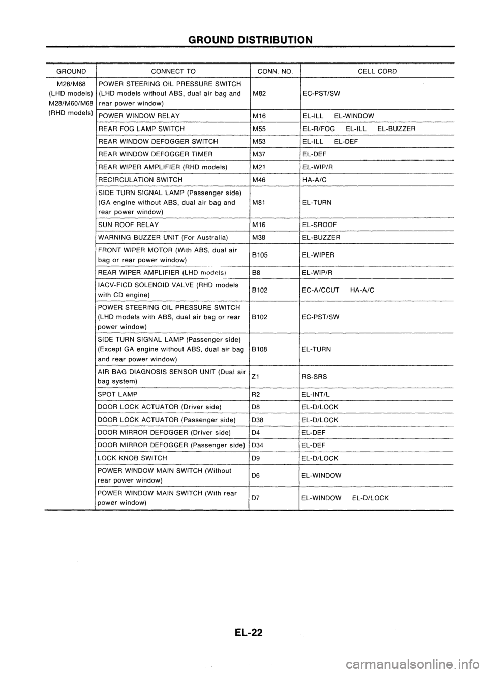
GROUNDDISTRIBUTION
GROUND CONNECTTO CONN.
NO. CELLCORD
E37/E51 AIRBAG DIAGNOSIS SENSORUNIT(Single
E108 RS-SRS
air bag system)
BRAKE FLUIDLEVEL SWITCH E2EL-WARN
CLEARANCE LAMPLH E50EL-TAILIL
CLEARANCE LAMPRH E33EL-TAILIL
COOLING FANMOTOR-1 (1-modetype) E45 EC-COOLIFHA-A/C
COOLING FANMOTOR-1 (2-modetype-GA
E66 EC-COOLIF
HA-A/C
engine forEurope)
COOLING FANMOTOR-1 (2-modetype-ex-
E46 EC-COOLIF
HA-A/C
eept GAengine forEurope)
COOLING FANMOTOR-2 (1-modetype)
E39 EC-COOLIFHA-A/C
-
COOLING FANMOTOR-2 (2-modetype-GA
E67 EC-COOLiF
HA-A/C
engine forEurope)
COOLING FANMOTOR-2 (2-modetype-ex-
E40 EC-COOLIFHA-A/C
eept GAengine forEurope)
COOLING FANRELAY-1 E12
EC-COOLIFHA-A/C
COOLING FANRELAY-2 E17
EC-COOLIFHA-A/C
COOLING FANRELAY-3 E18EC-COOLIF
HA-A/C
DAYTIME LIGHTUNIT E119EL-DTRL
FRONT FOGLAMP LH E52EL-F/FOG
FRONT FOGLAMP RH
E36EL-F/FOG
FRONT TURNSIGNAL LAMPLH E53EC-TURN
FRONT TURNSIGNAL LAMPRH E32EC-TURN
FRONT WIPERANDWASHER SWITCH E113
EL-WIPER
FUEL FILTER SWITCH
E5EL-WARN
HEADLAMP AIMINGMOTOR UNITLH E48
EL-AIM
HEADLAMP AIMINGMOTOR UNITRH E35 EL-AIM
HEADLAMP LH E49EL-H/LAMP
EL-DTRL
HEADLAMP RH E34EL-H/LAMP
EL-DTRL
HEADLAMP WIPERMOTOR LH E44
EL-HLC
HEADLAMP WIPERMOTOR RH E41EL-HLC
IACV-FICD SOLENOID VALVE(LHDmodels
.
E65 EC-A/CCUTHA-A/C
with CD20 engine)
INHIBITOR SWITCH E222EC-PNP/SWAT-A
IT EL-START
NEUTRAL POSITION SWITCH E220EC-PNP/SW
POWER STEERING OILPRESSURE SWITCH
E3 EC-PST/SW
(RHO models withgasoline engine)
REAR FOGLAMP RELAY E20EL-R/FOG
REAR WIPER ANDWASHER SWITCH E112EL-WIP/R
REAR WIPER RELAY E15EL-WIP/R
SIDE TURN SIGNAL LAMP(Driver side) E1 EL-TURN
WASHER FLUIDLEVEL SWITCH E30EL-WARN
EL-20
Page 394 of 1701

GROUNDDISTRIBUTION
GROUND CONNECT
TO CONN.NO.
CELLCORD
M28/M68
POWERSTEERING OILPRESSURE SWITCH
(LHD models) (LHDmodels withoutA8S,dualairbag and M82 EC-PST/SW
M28/M60/M68
rearpower window)
(RHD models)
POWERWINDOW RELAY
M16EL-ILLEL-WINDOW
REAR FOGLAMP SWITCH M55EL-R/FOGEL-ILLEL-8UZZER
REAR WINDOW DEFOGGER SWITCH M53EL-ILLEL-DEF
REAR WINDOW DEFOGGER TIMER M37EL-DEF
REAR WIPER AMPLIFIER (RHDmodels) M21EL-WIP/R
RECIRCULATION SWITCH M46HA-A/C
SIDE TURN SIGNAL LAMP(Passenger side)
(GA engine without A8S,dualairbag and M81 EL-TURN
rear power window)
SUN ROOF RELAY M16EL-SROOF
WARNING 8UZZERUNIT(ForAustralia)
M38EL-8UZZER
FRONT WIPERMOTOR (WithA8S,dualair
8105 EL-WIPER
bag orrear power window)
-_._-
-
REAR WIPER AMPLIFIER (LHDmodelsl 88EL-WIP/R
0-
IACV-FICD SOLENOID VALVE(RHDmodels
8102 EC-A/CCUTHA-A/C
with CDengine)
POWER STEERING OILPRESSURE SWITCH
(LHD models withASS, dualairbag orrear 8102 EC-PST/SW
power window)
SIDE TURN SIGNAL LAMP(Passenger side)
(Except GAengine without A8S,dualairbag 8108 EL-TURN
and rear power window)
AIR 8AG DIAGNOSIS SENSORUNIT(Dual air
Z1 RS-SRS
bag system)
SPOT LAMP
R2EL-INT/L
DOOR LOCKACTUATOR (Driverside)
D8 EL-D/LOCK
DOOR LOCKACTUATOR (Passengerside)
D38 EL-D/LOCK
DOOR MIRROR DEFOGGER (Driverside)
D4 EL-DEF
DOOR MIRROR DEFOGGER (Passengerside)
D34 EL-DEF
LOCK KN08 SWITCH
D9EL-D/LOCK
POWER WINDOW MAINSWITCH (Without
D6 EL-WINDOW
rear power window)
POWER WINDOW MAINSWITCH (Withrear
D7 EL-WINDOW EL-D/LOCK
power window)
EL-22