Page 1678 of 1701
SEC.488 STEERING
WHEELANDSTEERING COLUMN
Disassembly andAssembly
~.N.m (kg-m, in-Ib)
~ .N.m (kg-m, ft-Ib)
SST539C
G)
Spiral cable
@
Combination switch
@
Lock nut
@
Tiltlever
@
Washer
@
Tiltlever stopper
!J)
Steering columnmounting
bracket
@
Adjust bolt
CID
Adjust boltstopper
@J
Push nut
@
Jacket tubeassembly
@
Boot
@
Steering columnshaft
@
Lower joint
@
Return spring
Lock nut
II
I
•
When disassembling andassembling, unlocksteering lock
with key.
• Install locknutonsteering columnshaftandtighten thenut
to specification.
~: 25-34 N.m (2.5-3.5 kg-m, 18-25 ft-Ib)
SST490C ST-12
Page 1679 of 1701
STEERINGWHEELANDSTEERING COLUMN
Disassembly andAssembly (Cont'd)
• Steering lock
a. Break self-shear typescrews withadrill orother appropri-
ate tool.
SST741A
b.Install newself-shear typescrews andthen cutoffself-
shear typescrew heads.
Self-shear screw
SST742A
L
-
--- ---_
..
_-------,
I
Center ofjoint
SST334C
1510.59) 15 (0.59)
Inspection
• When steering wheeldoesnotturn smoothly, checkthe
steering columnasfollows andreplace damaged parts.
a. Check column bearings fordamage orunevenness. Lubri-
cate with recommended multi-purposegreaseorreplace
steering columnasan assembly, ifnecessary.
b. Check jackettubefordeformation orbreakage. Replaceif
necessary.
• When thevehicle comesintoalight collision, checklength
ilL",
Column length
"L": •
533.0 -535.0 mm(20.98 -21.06 in)
If out ofthe specifications, replacesteering columnasan
assembly.
Tilt mechanism
• After installing steeringcolumn,checktiltmechanism oper-
ation.
Unit: mm(in)
8ST5828
ST-13
Page 1680 of 1701
MANUALSTEERING GEARANDLINKAGE (ModelR24N)
Removal andInstallation
SEC. 480
A :
N.m (kg-m, tt-Ib)
(!)
Hole cover
@
Lower joint
@
Manual steering gearassembly
@
Steering gearmounting clamp
tt'J
29•39
(3.0 -4.0,22 -", ~
~
@~ SST056CA
@
Rack mounting insulator
@
Cotter pin
CAUTION:
The rotation ofthe spiral cable(SRS"Airbag" component part)
is limited.
If
the steering gearmust beremoved, setthe front
wheels inthe straight-ahead direction.Donot rotate thesteer-
ing column whilethesteering gearisremoved.
• Detach tie-rodoutersockets fromknuckle armswithTool.
• Initially, tightennutontie-rod outersocket andknuckle arm
to 29 to39 N'm (3to 4kg-m, 22to29 ft-Ib).
• Tighten nutfurther toalign nutgroove withthefirst pinhole
so cotter pincan beinstalled.
CAUTION:
Tightening torquemustnotexceed 49N.m (5kg-m, 36ft-Ib).
ST-14
Page 1681 of 1701

MANUALSTEERING GEARANDLINKAGE (ModelR24N)
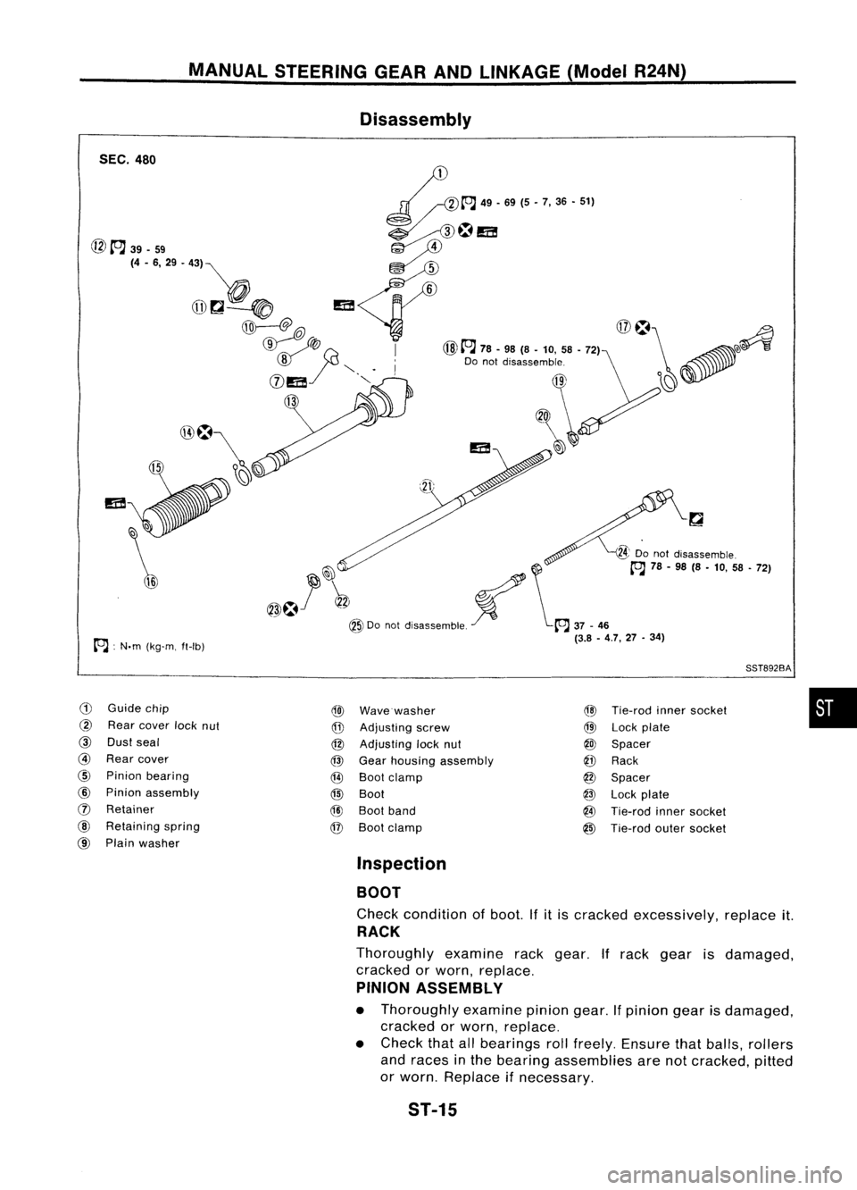
Disassembly
SEC. 480
•
SST892BA
@
Tie-rod innersocket
@
Lock plate
@)
Spacer
@
Rack
@
Spacer
@
Lock plate
@
Tie-rod innersocket
@
Tie-rod outersocket
@)
Wave washer
@
Adjusting screw
@
Adjusting locknut
@
Gear housing assembly
@
Boot clamp
@
Boot
@J
Boot band
@
Boot clamp
24'
Do not disassemble.
!ill \
[OJ
78-98 (S-10, 58-72)
~~;:1' \~~~
Dooot d,,,,,,mbt, ~
[OJ
37_"
(3.8 -4.7, 27-34)
~[OJ
49-69(5 -7,36 -51}
~~~m
@ A 39-59 ~
)!l
(4 -6, 29 .43) ""
-=-
q=
5
_~ 0
6
@~~
m
(j];=-@
@~
8
'Donotdisassemble
WIlEi'! "-".
~9
0
13
\
A :
N.m (kg-m, ft-Ib)
CD
Guide chip
@
Rear cover locknut
@
Dustseal
@
Rear cover
@
Pinion bearing
@
Pinion assembly
(j)
Retainer
@
Retaining spring
@
Plain washer
Inspection
BOOT
Check condition ofboot. Ifitis cracked excessively, replaceit.
RACK
Thoroughly examinerackgear. Ifrack gear isdamaged,
cracked orworn, replace.
PINION ASSEMBLY
• Thoroughly examinepiniongear.Ifpinion gearisdamaged,
cracked orworn, replace.
• Check thatallbearings rollfreely. Ensure thatballs, rollers
and races inthe bearing assemblies arenotcracked, pitted
or worn. Replace ifnecessary.
ST-15
Page 1682 of 1701

MANUALSTEERING GEARANDLINKAGE (ModelR24N)
Inspection (Cont'd)
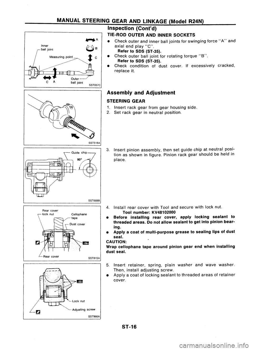
TIE-ROD OUTERANDINNER SOCKETS
...... A •
Check outerandinner balljoints for
swinging
force"A"and
axial endplay "C".
Refer toSOS CST-35).
Measuring point •
Check outerballjoint forrotating torque"B".
Refer toSOS CST-35).
• Check condition ofdust cover. Ifexcessively cracked,
replace it.
SST057C Assembly andAdjustment
STEERING GEAR
1. Insert rackgear from gearhousing side.
2. Set rack gear inneutral position.
SST518A
GO":,%?
'~
SST6688
3.
Insert pinion assembly, thensetguide chipatneutral posi-
tion asshown infigure. Pinionrackgear should be
held
in
place.
SST815A
4.
Install rearcover withTool andsecure withlocknut.
Tool number: KV48102000
• Before installing rearcover, applylocking sealant to
threaded areas.Donot allow sealant toget into pinion bear-
ing.
• Apply acoat ofmulti-purpose greasetosealing lipsofdust
seal.
CAUTION:
Wrap cellophane tapearound piniongearendwhen installing
dust seal.
5. Insert retainer, spring,plainwasher andwave washer.
Then, install adjusting screw.
• Apply acoat oflocking sealant tothreaded areasofretainer
cover.
Adjusting screw
SST966A
5T-16
Page 1683 of 1701

SST272A
Pinion
rotating
torque
MANUAL
STEERING GEARANDLINKAGE (ModelR24N)
Assembly andAdjustment (Cant'd)
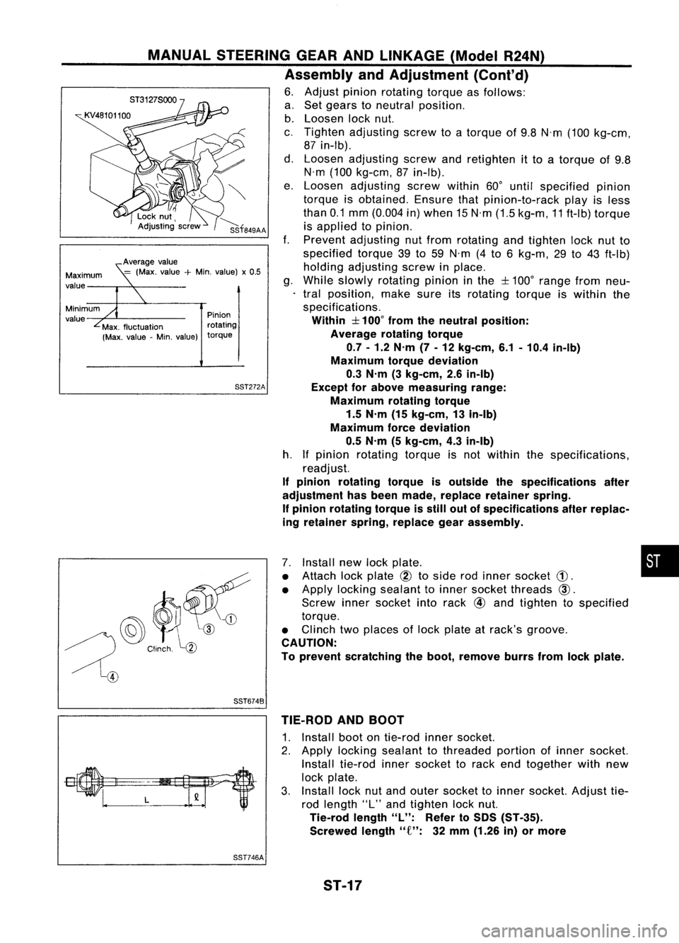
6. Adjust pinionrotating torqueasfollows:
a. Set gears toneutral position.
b. Loosen locknut.
c. Tighten adjusting screwtoatorque of9.8 N'm (100 kg-cm,
87 in-Ib).
d. Loosen adjusting screwandretighten itto atorque of9.8
N'm (100 kg-cm, 87in-Ib).
e. Loosen adjusting screwwithin60°until specified pinion
torque isobtained. Ensurethatpinion-to-rack playisless
than 0.1mm (0.004 in)when 15N'm (1.5kg-m, 11ft-Ib) torque
is applied topinion.
f. Prevent adjusting nutfrom rotating andtighten locknutto
specified torque39to59 N'm (4to 6kg-m, 29to43 ft-Ib)
holding adjusting screwinplace.
g. While slowly rotating pinioninthe
:f::
100° range fromneu-
tral position, makesureitsrotating torqueiswithin the
specifications.
Within
:f::
100° from theneutral position:
Average rotatingtorque
0.7 -1.2 N'm (7-12 kg-em, 6.1-10.4 in-Ib)
Maximum torquedeviation
0.3 N'm (3kg-em, 2.6in-Ib)
Except forabove measuring range:
Maximum rotatingtorque
1.5 N'm (15kg-em, 13in-Ib)
Maximum forcedeviation
0.5 N'm (5kg-em, 4.3in-Ib)
h. Ifpinion rotating torqueisnot within thespecifications,
readjust.
If pinion rotating torqueisoutside thespecifications after
adjustment hasbeen made, replace retainer spring.
If pinion rotating torqueisstill outofspecifications afterreplac-
ing retainer spring,replace gearassembly.
Average
value
=
(Max. value
+
Min. value) x0.5
Minimum
value Maximum
value
@~~
/) Clinch
l(1)
~@
7.
Install newlockplate. •
• Attach lockplate
@
toside rodinner socket
CD.
• Apply locking sealant toinner socket threads
CID.
Screw innersocket intorack
@
and tighten tospecified
torque.
• Clinch twoplaces oflock plate atrack's
groove.
CAUTION:
To prevent scratching theboot, remove burrsfromlockplate.
SST6748 TIE-ROD ANDBOOT
1. Install bootontie-rod innersocket.
2. Apply locking sealant tothreaded portionofinner socket.
Install tie-rod innersocket torack endtogether withnew
lock plate.
3. Install locknutand outer socket toinner socket. Adjusttie-
rod length "L"and tighten locknut.
Tie-rod length
"L":
Referto50S (ST-35).
Screwed length"
f":
32mm (1.26 in)ormore
SST746A
ST-17
Page 1684 of 1701
MANUALSTEERING GEARANDLINKAGE (ModelR24N)
Assembly andAdjustment
(Cont'd)
4. Measure rackstroke.
Measure stroke
"S":
Refer toSOS (ST-35).
AST141
5.Before installing boot,coatthecontact surfaces between
boot andtie-rod withgrease.
~==--
SST967A
6.Install bootclamps.
• Toinstall, wrapbootclamp around bootgroove twice.Use
a screwdriver totighten clamps. Twistringsatboth ends 4
to 4-1/2 turns while pulling themwithaforce ofapprox. 98
N (10 kg,22lb).
• Donot cross wireonboot.
AST137
•Bend twisted endofboot clamp asshown atleft. (This will
prevent interference withother parts.)
AST138
ST-18
Page 1685 of 1701

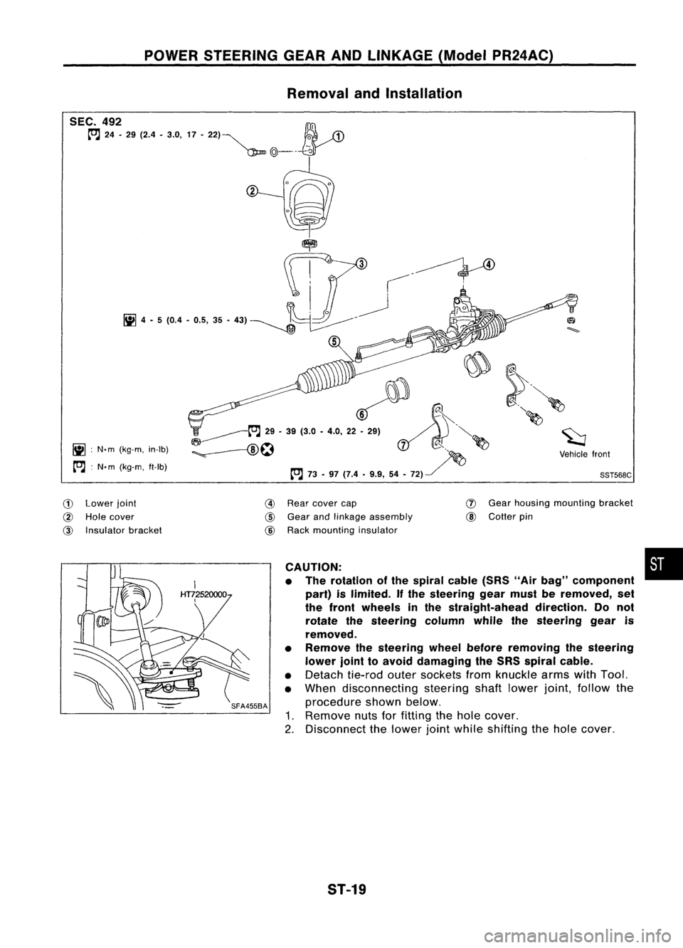
POWERSTEERING GEARANDLINKAGE (ModelPR24AC)
Removal andInstallation
~ :N.m (kg-m, in-Ib)
[O.J :
N. m (kg-m, ft-Ib)
~~.~
';'-------t"J
29•39 (3.0 •4.0, 22~ ~.'.. ~"'-
:;. --f8\~ ~
d( ~ ~
~ ~~ ~Vehiclefront
[O.J
73-97 (7.4 •9.9, 54•72) ~
'
SST568C
CD
Lower joint
@
Hole cover
@
Insulator bracket
@
Rear cover cap
@
Gear andlinkage assembly
@
Rack mounting insulator
(J)
Gear housing mounting bracket
@
Cotter pin
CAUTION: •
• The rotation ofthe spiral cable(SRS"Airbag" component
part) islimited.
If
the steering gearmust beremoved, set
the front wheels inthe straight-ahead direction.Donot
rotate thesteering columnwhilethesteering gearis
removed.
• Remove thesteering wheelbefore removing thesteering
lower jointtoavoid damaging theSRS spiral cable.
• Detach tie-rodoutersockets fromknuckle armswithTool.
• When disconnecting steeringshaftlower joint,follow the
procedure shownbelow.
1. Remove nutsforfitting thehole cover.
2. Disconnect thelower jointwhile shifting thehole cover.
ST-19