Page 1686 of 1701

POWERSTEERING GEARANDLINKAGE (ModelPR24AC)
Removal andInstallation (Cont'd)
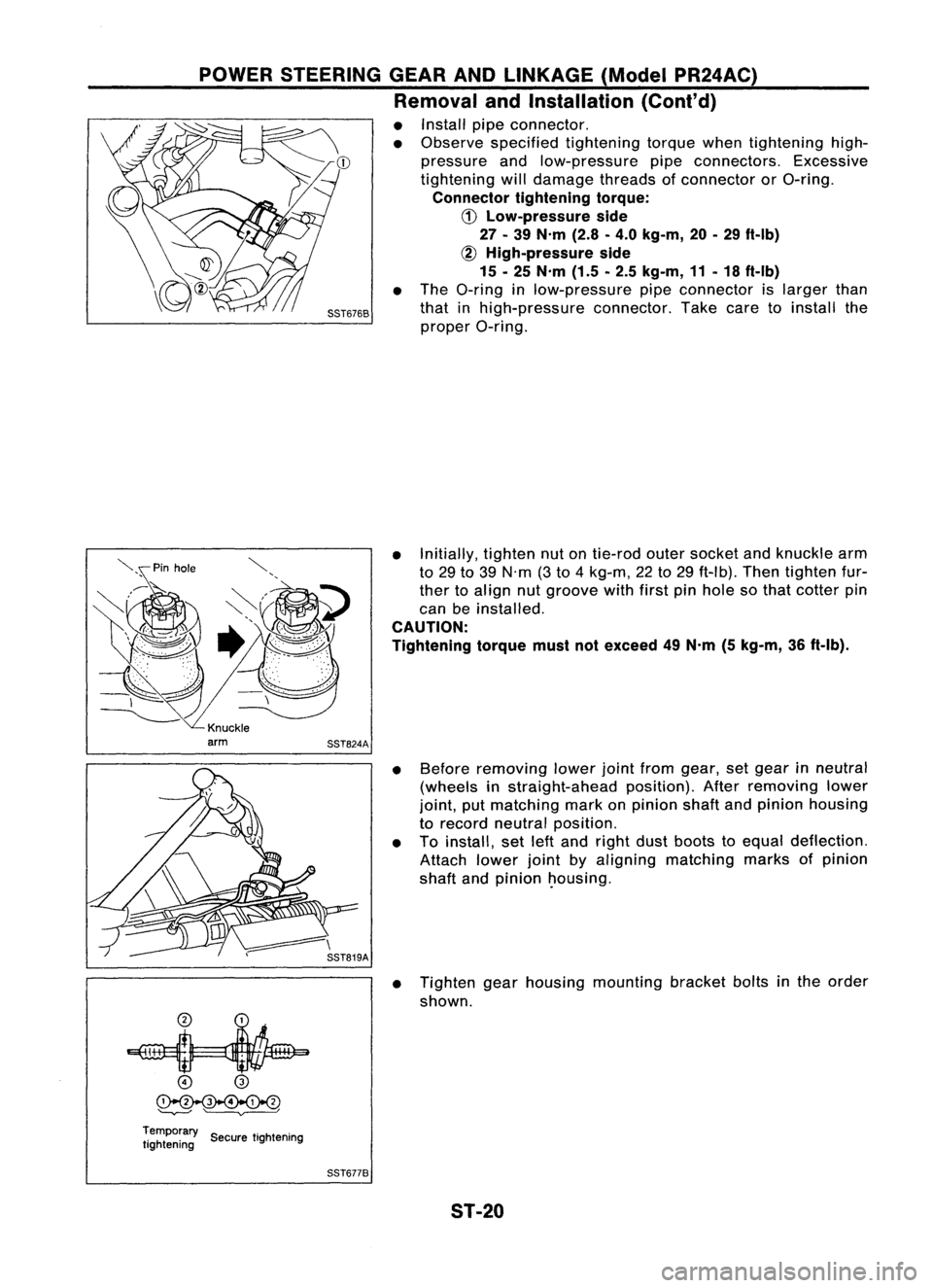
• Install pipeconnector.
• Observe specified tightening torquewhentightening high-
pressure andlow-pressure pipeconnectors. Excessive
tightening willdamage threadsofconnector orO-ring.
Connector tighteningtorque:
CD
Low-pressure side
27 -39 N'm (2.8-4.0 kg-m, 20-29 ft-Ib)
~ High-pressure side
15 -25 N'm (1.5-2.5 kg-m, 11-18 ft-Ib)
• The O-ring inlow-pressure pipeconnector islarger than
that inhigh-pressure connector.Takecaretoinstall the
proper O-ring.
• Initially, tightennutontie-rod outersocket andknuckle arm
to 29 to39 N'm (3to 4kg-m, 22to29 ft-Ib). Thentighten fur-
ther toalign nutgroove withfirstpinhole sothat cotter pin
can beinstalled.
CAUTION:
Tightening torquemustnotexceed 49N'm (5kg-m, 36ft-Ib).
• Before removing lowerjointfrom gear, setgear inneutral
(wheels instraight-ahead position).Afterremoving lower
joint, putmatching markonpinion shaftandpinion housing
to record neutral position.
• Toinstall, setleftand right dustboots toequal deflection.
Attach lowerjointbyaligning matching marksofpinion
shaft andpinion ~ousing.
• Tighten gearhousing mounting bracketboltsinthe order
shown.
o
@
~
'--v---' ~
Temporary ..
tightening SecuretIghtening
SST6778
ST-20
Page 1687 of 1701
![NISSAN ALMERA N15 1995 Service Manual POWERSTEERING GEARANDLINKAGE (ModelPR24AC)
•
~ :N.m (kg-m. ft-lb)
f] :
Lubrication points
(With automatic
transmission fluid
"DEXRON'u" type
or equivalent)
I
@~~~~
~~(SRandCD
~ ~~ e NISSAN ALMERA N15 1995 Service Manual POWERSTEERING GEARANDLINKAGE (ModelPR24AC)
•
~ :N.m (kg-m. ft-lb)
f] :
Lubrication points
(With automatic
transmission fluid
"DEXRON'u" type
or equivalent)
I
@~~~~
~~(SRandCD
~ ~~ e](/manual-img/5/57349/w960_57349-1686.png)
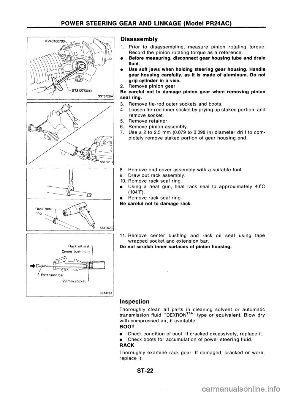
POWERSTEERING GEARANDLINKAGE (ModelPR24AC)
•
~ :N.m (kg-m. ft-lb)
f] :
Lubrication points
(With automatic
transmission fluid
"DEXRON'u" type
or equivalent)
I
@~~~~
~~(SRandCD
~ ~~ enginemodels)
8
~78. 98
(8.0 •10.0,
58•72)
GA engine model
~ 37•46 (3.8 •4.7, 27.34)
CD and SRengine models
M
78.98
(8.0 •
10.0, 58•72)
(SR
,,'CD,",,",
m_"'7
~\Il~
m~
@,
~16.21
~~'" ~•'.1, ". 1S(
r
""'---l
, @
l"J
::'0' ,':0,
1
I
~ /7'
~y
@ "-~~(]
tGi ~
~m
@
t:;;J
~20.
26
(2.0 •2.7, 14•20)
SEC.
492
@)(]~\-
.~
~'
r
L
~to:J59' 74
20~
(6.0 •
7.5, 43.54)
_~ @Donotdisas~smble.
0
to:J 29•39
{3.0 .4.0,22. "~~
SST506CA
Pinion oilseal
Lock nut
Adjusting screw
Spring
Spring disc
G)
Rear cover cap
@
Rear housing assembly
@
Pinion sealring
@
Pinion assembly
CID
O-ring
@
Shim
(J)
@
@
@)
@ @
Washer
@
Spring seat
@
Retainer
@
Gear housing
@
Center bushing
@
Rack oilseal
@
Rack assembly
@
Rack sealring
@)
O-ring
@
Rack oilseal
@
Endcover assembly
@
Boot clamp
@
Dust boot
@
Boot band
@l
Steering gearspacer
@
Lock plate
@
Tie-rod innersocket
@
Tie-rod outersocket
@
Cotter pin
@
Gear housing tube
ST-21
Page 1688 of 1701

POWERSTEERING GEARANDLINKAGE (ModelPR24AC)
Disassembly
1. Prior todisassembling, measurepinionrotating torque.
Record thepinion rotating torqueasareference.
• Before measuring, disconnectgearhousing tubeanddrain
fluid.
• Use softjaws when holding steering gearhousing. Handle
gear housing carefully, asitis made ofaluminum. Donot
grip cylinder inavise.
2. Remove piniongear.
Be careful nottodamage piniongearwhen removing pinion
seal ring.
3. Remove tie-rodoutersockets andboots.
4. Loosen tie-rodinnersocket byprying upstaked portion, and
remove socket.
5. Remove retainer.
6. Remove pinionassembly.
7. Use a2to 2.5 mm (0.079 to0.098 in)diameter drilltocom-
pletely remove stakedportion ofgear housing end.
8. Remove endcover assembly withasuitable tool.
9. Draw outrack assembly.
10. Remove rackseal ring.
• Using aheat gun,heat racksealtoapproximately 40°C
(104°F).
• Remove racksealring.
Be careful nottodamage rack.
11. Remove centerbushing andrack oilseal using tape
wrapped socketandextension bar.
Do not scratch innersurfaces ofpinion housing .
.. !tension bar
29 mm socket
SST472AInspection
Thoroughly cleanallparts incleaning solventorautomatic
transmission fluid''DEXRON™,, typeorequivalent. Blowdry
with compressed air,ifavailable.
BOOT
• Check condition ofboot. Ifcracked excessively, replaceit.
• Check bootsforaccumulation ofpower steering fluid.
RACK
Thoroughly examinerackgear. Ifdamaged, crackedorworn,
replace it.
ST-22
Page 1689 of 1701

POWERSTEERING GEARANDLINKAGE (ModelPR24AC)
Inspection (Cont'd)
PINION ASSEMBLY
• Thoroughly examinepiniongear.Ifpinion gearisdamaged,
cracked orworn, replace it.
• Check thatallbearings rollfreely. Ensure thatballs, rollers
and races arenotcracked, pittedorworn. Replace ifnec-
essary.
GEAR HOUSING CYLINDER
Check gearhousing cylinder boreforscratches orother dam-
age. Replace ifnecessary.
SST083B
•
2.
Using Tool,compress rackseal ringsecurely ontorack.
Always insertToolfrom therack gear side.
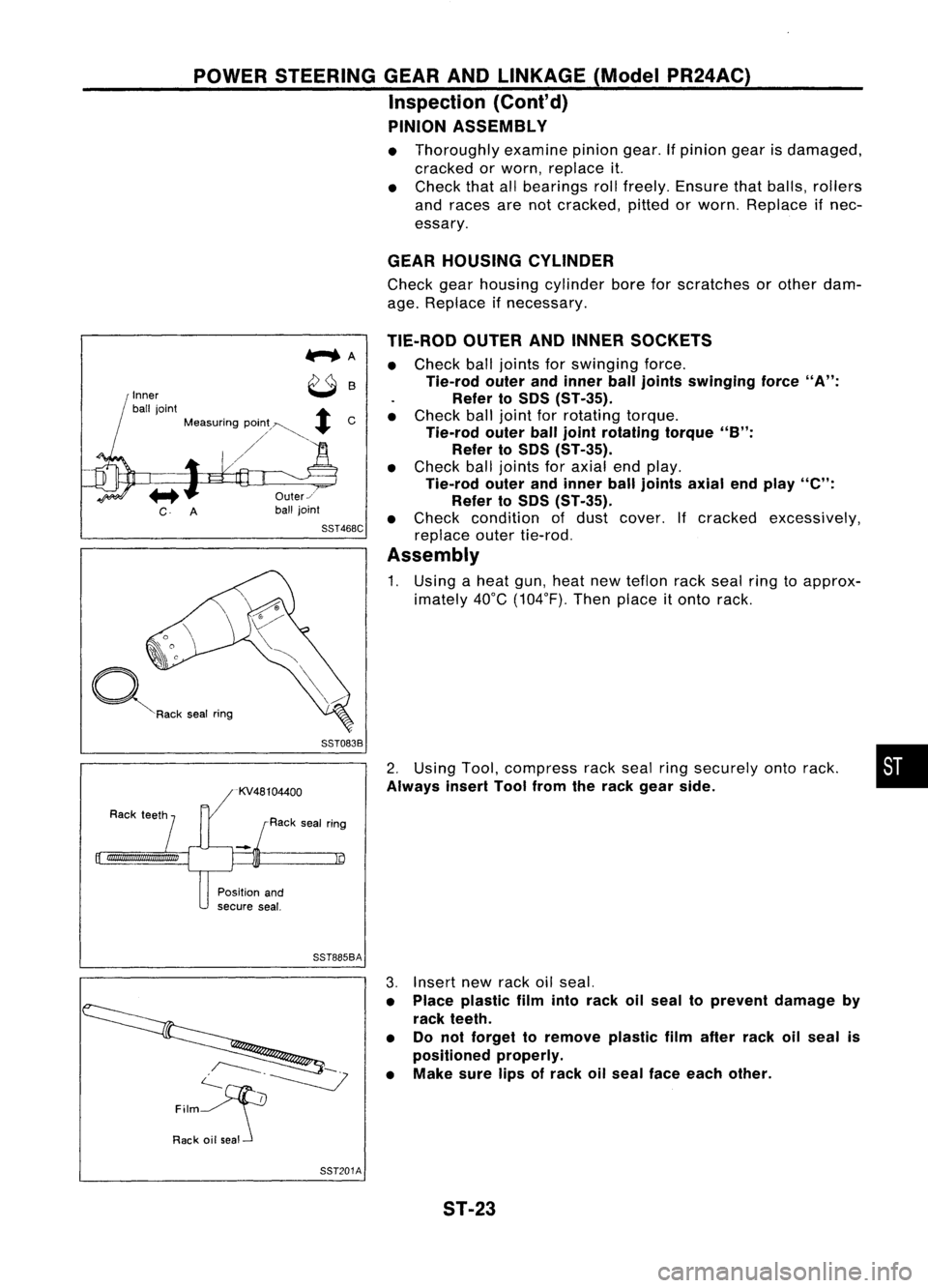
TIE-ROD
OUTERANDINNER SOCKETS
• Check balljoints forswinging force.
Tie-rod outerandinner ball
joints
swinging force
"A":
Refer toSOS (ST-35).
• Check balljoint forrotating torque.
Tie-rod outerballjoint rotating torque
"B":
Refer to50S (ST-35).
• Check balljoints foraxial endplay.
Tie-rod outerandinner balljoints axialendplay
"e":
Refer to50S (ST-35).
• Check condition ofdust cover. Ifcracked excessively,
replace outertie-rod.
Assembly
1. Using aheat gun,heat newteflon rackseal ringtoapprox-
imately 40°C(104°F). Thenplace
it
onto rack.
Us
Rack sealring
Inner
ball joint
+
Measuring pOin;~~
+
C
/'
~R"k ,.. I
""9
Position and
secure seal.
SST885BA
c--.~
~
Film
Rack oilseal 3.
Insert newrack oilseal.
• Place plastic filmintorack oilseal toprevent damage by
rack teeth.
• Donot forget toremove plasticfilmafter rackoilseal is
positioned properly.
• Make surelipsofrack oilseal face each other.
SST201A ST-23
Page 1690 of 1701
POWERSTEERING GEARANDLINKAGE (ModelPR24AC)
Assembly (Conl'd)
4. Install center bushing andrack oilseal with rackassembly.
SST830A
5.Insert rackoilseal andendcover assembly torack. Then
tighten endcover assembly.
End cover assembly
SST321B
2-3mm
(0.08 •0.12 In)
SST073B
SST086BA
6.
Fasten endcover assembly togear housing bystaking.
7. Set rack gear inneutral position.
Rack stroke
"5":
Refer to50S (ST-35).
Suitable tool
Oil seal
SST381A
8.
Coat seallipofnew pinion oilseal with multi-purpose
grease. Installitinto pinion housing ofgear withasuitable
tool.
Make surelipofoil seal faces upwhen installed.
ST-24
Page 1691 of 1701
POWERSTEERING GEARANDLINKAGE (ModelPR24AC)
Assembly (Cont'd)
9. Install pinionbearing adjusting shim(s).
• Whenever pinionassembly, gearhousing andrear housing
are disassembled, replaceshim(s)withnewones. Always
use thesame number ofshim(s) whenreplacing.
SST074B
10.Install newpinion sealring(made ofTeflon) onpinion gear
assembly.
• Using aheat gun, heatpinion sealringtoapproximately
. 40°C (104°F) beforeinstalling itonto pinion gearassembly.
• Make surepinion sealringisproperly settledinvalve
groove.
SST085B
11.Apply acoat ofmulti-purpose greasetoneedle bearing
roller andoilseal lip.
SST075B
12.Install pinionassembly torear housing.
Be careful nottodamage pinionoilseal.
SST552
•
13. Apply acoat ofmulti-purpose greasetonew rearoilseal lip
before installing rearhousing.
Gear housing
SST133C ST-25
Page 1692 of 1701
POWERSTEERING GEARANDLINKAGE (ModelPR24AC)
Assembly (Cont'd)
14. Ensure thattherack iscentered. Installrearcover capso
that itsprotrusion ispositioned asshown infigure.
Be careful nottodamage wormringandoilseal.
88T507C
15.Install diaphragm springintogear housing.
• Always installretainer, springwasher anddiaphragm
spring inthat order.
• Make sureconvex end(painted white)ofdiaphragm spring
faces outward wheninstalling.
16. Install retainer springandadjusting screwtemporarily.
88T0878
17.Install newlockplate.
a. Attach lockplate
@
toside rodinner socket
(!).
b. Insert steering gearspacer
CID
torack
@.
c. Apply locking sealant toinner socket threads
CID.
Screw innersocket intorack
@
and tighten tospecified
torque.
d. Stake lockplate attwo places.
CAUTION:
To prevent scratching theboot, remove burrsfromlockplate.
18. Tighten outersocket locknut.
Tie-rod length
"L":
Refer toSOS (ST-35).
88T0938
19.Measure rackstroke.
Rack stroke
"5":
Refer to50S (ST-35).
s
88T0868A ST-26
Page 1693 of 1701

POWERSTEERING GEARANDLINKAGE (ModelPR24AC)
Assembly (Cont'd)
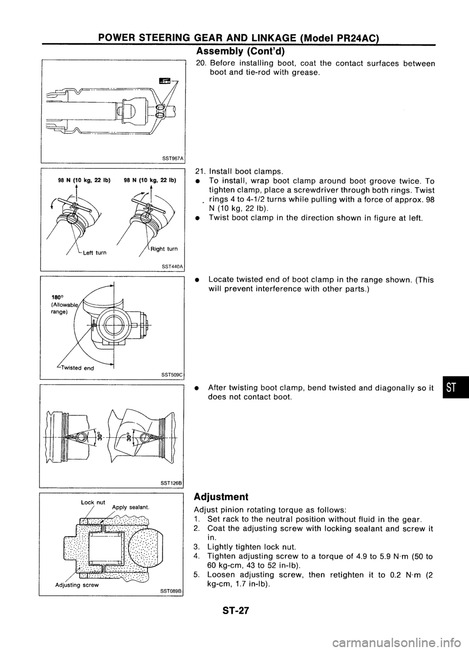
20. Before installing boot,coatthecontact surfaces between
boot andtie-rod withgrease.
88T967A
21.Install bootclamps.
• Toinstall, wrapbootclamp around bootgroove twice.To
tighten clamp,placeascrewdriver throughbothrings. Twist
rings 4to 4-1/2 turns while pulling withaforce ofapprox. 98
N (10 kg,22Ib).
• Twist bootclamp inthe direction showninfigure atleft.
88T440A
•Locate twisted endofboot clamp inthe range shown. (This
will prevent interference withother parts.)
88TS09C
88T1268
•
After twisting bootclamp, bendtwisted anddiagonally soit •
does notcontact boot.
Adjusting screw
88T0898Adjustment
Adjust pinionrotating torqueasfollows:
1. Set rack tothe neutral position withoutfluidinthe gear.
2. Coat theadjusting screwwithlocking sealant andscrew it
in.
3. Lightly tighten locknut.
4. Tighten adjusting screwtoatorque of4.9 to5.9 N'm (50to
60 kg-em, 43to52 in-Ib).
5. Loosen adjusting screw,thenretighten itto 0.2 N'm (2
kg-em, 1.7in-Ib).
ST-27