Page 624 of 1701
3.Insert NATSprogram cardintoCONSULT.
+:
Program card
NATS-E940
4. Turn onignition switch.
5. Touch "START".
NISSAN NATS
(Nissan Anti-Theft System)
Trouble Diagnoses (Cont'd)
CONSULT INSPECTION PROCEDURE
1. Turn offignition switch.
2. Connect "CONSULT" toData linkconnector forCONSULT.
(Data linkconnector forCONSULT islocated behindthefuse
box cover.)
CONSULT
~====Iij-=:J
START
I
SEL327U
~ SELECT NATSSYSTEM
0
I
6.
Touch "V.2.0(GASOLINE)".
V.1.0
V. 2.0(GASOLINE)
V. 2.0(DIESEL)
SEL328U
~ SELECT DIAGMODE
D
c/u INITIALISATION
SELF-DIAG RESULTS
SELF-FUNCTION CHECK
7.
Perform eachdiagnostic testmode according toeach ser-
vice procedure.
For further information, seetheCONSULT OperationManual,
NATS V2.0.
SEL329U
EL-252
Page 626 of 1701
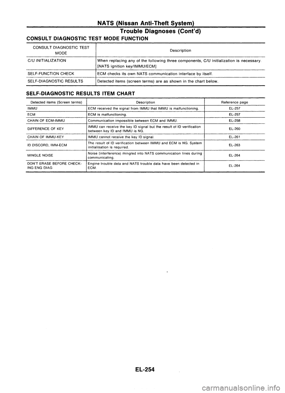
NATS(Nissan Anti-Theft System)
Trouble Diagnoses (Cont'd)
CONSULT DIAGNOSTIC TESTMODE FUNCTION
CONSULT DIAGNOSTIC TEST
MODE
C/U
INITIALIZATION
SELF-FUNCTION CHECK
SELF-DIAGNOSTIC RESULTS Description
When replacing anyofthe following threecomponents,
C/U
initialization isnecessary.
[NATS ignition key/lMMU/ECMj
ECM checks itsown NATS communication interfacebyitself.
Detected items(screen terms)areasshown inthe chart below.
SELF-DIAGNOSTIC RESULTSITEMCHART
Detected items(Screen terms) Description Reference
page
IMMU ECMreceived thesignal fromIMMU thatIMMU ismalfunctioning. EL-257
ECM ECMismalfunctioning. EL-257
CHAIN OFECM-IMMU CommunicationimpossiblebetweenECMandIMMU. EL-258
DIFFERENCE OFKEY IMMU
canreceive thekey
10
signal butthe result ofID verification
EL-260
between keyIDand IMMU isNG.
CHAIN OFIMMU-KEY
IMMUcannot receive thekey IDsignal. EL-261
ID DISCORD, IMM-ECM The
result of
10
verification betweenIMMUandECM isNG. System
EL-263
initialisation isrequired.
MINGLE NOISE Noise
(interference) mingledintoNATS communication linesduring
EL-264
communicating.
DON'T ERASE BEFORE CHECK-
Enginetrouble dataandNATS trouble datahave beendetected in
EL-264
ING ENG DIAG ECM.
EL-254
Page 641 of 1701
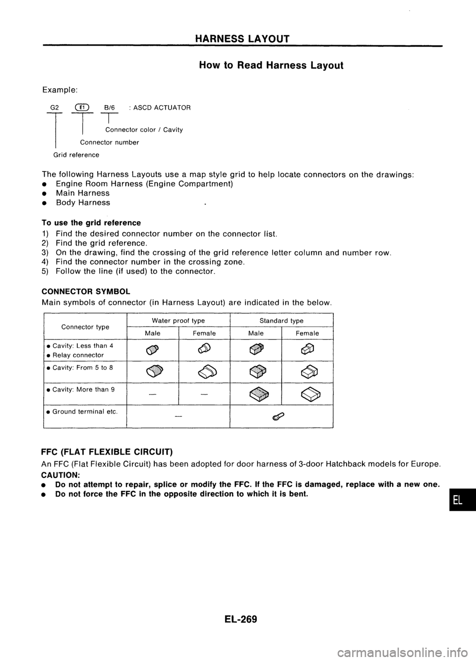
HARNESSLAYOUT
How toRead Harness Layout
Example:
G2
@
8/6:ASCD ACTUATOR
T
T
~nector color/Cavity
Connector number
Grid reference
The following HarnessLayoutsuseamap style gridtohelp locate connectors onthe drawings:
• Engine RoomHarness (EngineCompartment)
• Main Harness
• Body Harness
To use thegrid reference
1) Find thedesired connector numberonthe connector list.
2) Find thegrid reference.
3) Onthe drawing, findthecrossing ofthe grid reference lettercolumn andnumber row.
4) Find theconnector numberinthe crossing zone.
5) Follow theline (ifused) tothe connector.
CONNECTOR SYMBOL
Main symbols ofconnector (inHarness Layout)areindicated inthe below.
Water prooftype Standardtype
Connector type
MaleFemale MaleFemale
•
Cavity:
Lessthan
4
~ ~
~
@i)
•
Relay
connector
•
Cavity:
From
5
to
8
~ ~~
c90
•
Cavity:
Morethan
9
$
~
-
-
•
Ground
terminal etc.
@?
-
FFC (FLAT FLEXIBLE CIRCUIT)
An FFC (Flat Flexible Circuit)hasbeen adopted fordoor harness of3-door Hatchback modelsforEurope.
CAUTION:
• Donot attempt torepair, spliceormodify theFFC. Ifthe FFC isdamaged, replacewithanew one.
• Donot force theFFC inthe opposite direction towhich itis bent.
EL-269
•
Page 721 of 1701
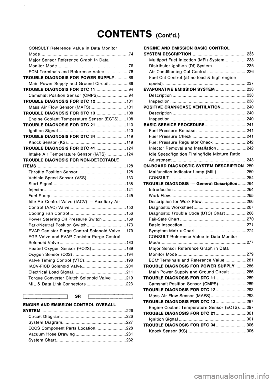
CONTENTS(Cont'd.)
CONSULT Reference ValueinData Monitor
Mode 74
Major Sensor Reference GraphinData
Monitor Mode 76
ECM Terminals andReference Value 78
TROUBLE DIAGNOSIS FORPOWER SUPPLY 88
Main Power Supply andGround Circuit.. 88
TROUBLE DIAGNOSIS FORDTC11 94
Camshaft PositionSensor(CMPS) 94
TROUBLE DIAGNOSIS FORDTC
12 101
Mass AirFlow Sensor (MAFS) 101
TROUBLE DIAGNOSIS FORDTC
13 108
Engine Coolant Temperature Sensor(ECTS) 108
TROUBLE DIAGNOSIS FORDTC
21 113
Ignition Signal 113
TROUBLE DIAGNOSIS FORDTC
34 119
Knock Sensor (KS) 119
TROUBLE DIAGNOSIS FORDTC
41 124
Intake AirTemperature Sensor(IATS) 124
TROUBLE DIAGNOSIS FORNON-DETECTABLE
ITEMS , '"
.128
Throttle Position Sensor 128
Vehicle SpeedSensor (VSS) 133
Start Signal 138
Injector 141
Fuel Pump 145
Idle AirControl Valve(IACV) -Auxiliary Air
Control (AAC)Valve 150
Cooling FanControl 156
Power Steering OilPressure Switch 169
Park/Neutral PositionSwitch 173
EVAP Canister PurgeControl Solenoid Valve179
EGR Valve andEVAP Canister PurgeControl
Solenoid Valve 183
Heated Oxygen Sensor(H02S) 189
Oxygen Sensor(02S) 194
Valve Timing Control (VTC) 198
IACV-FICD SolenoidValve 204
Electrical LoadSignal 211
Torque Converter ClutchSolenoid Valve 219
MIL
&
Data LinkConnectors 223
SR
ENGINE ANDEMISSION CONTROL OVERALL
SYSTE M
226
Circuit Diagram 226
System Diagram 227
ECCS Component PartsLocation 228
Vacuum HoseDrawing 231
System Chart... 232
ENGINE
ANDEMISSION BASICCONTROL
SYSTEM DESCRiPTION
233
Multipart FuelInjection (MFI)System 233
Distributor Ignition
(01)
System 235
Air Conditioning CutControl 236
Fuel CutControl (atnoload
&
high engine
speed) 237
EVAPORATIVE EMISSIONSYSTEM
238
Description 238
Inspection 238
POSITIVE CRANKCASE VENTILATION
240
Description 240
Inspection 240
BASIC SERVICE
PROCEDURE 241
Fuel Pressure Release 241
Fuel Pressure Check 241
Fuel Pressure Regulator Check 242
Injector Removal andInstallation 242
Idle Speed/Ignition Timing/IdleMixtureRatio
Adjustment 243
ON-BOARD DIAGNOSTIC SYSTEMDESCRIPTION ..250
Malfunction IndicatorLamp(MIL) 250
CONSULT 254
TROUBLE DIAGNOSIS -General Description
264
Introduction 264
Work Flow 265
Description forWork Flow 266
Diagnostic Worksheet 267
Diagnostic TroubleCode(DTC) Chart 268
Fail-Safe Chart 270
Basic Inspection 271
Symptom MatrixChart. 274
CONSULT Reference ValueinData Monitor
Mode 277
Major Sensor Reference GraphinData
Monitor Mode 279
ECM"Terminals andReference Value 281
TROUBLE DIAGNOSIS FORPOWER SUPPLY
286
Main Power Supply andGround Circuit.. 286
TROUBLE DIAGNOSIS FORDTC
11 289
Camshaft PositionSensor(CMPS) 289
TROUBLE DIAGNOSIS FORDTC
12 293
Mass AirFlow Sensor (MAFS) 293
TROUBLE DIAGNOSIS FORDTC
13 297
Engine Coolant Temperature Sensor(ECTS) 297
TROUBLE DIAGNOSIS FORDTC
21 301
Ignition Signal 301
TROUBLE DIAGNOSIS FORDTC
34 306
Knock Sensor (KS) 306
Page 737 of 1701
ENGINEANDEMISSION CONTROL OVERALLSYSTEM
ECCS Component PartsLocation -GA15DE
Distributor withbuilt-in camshaft position
sensor, powertransistor andignition coil
EGR
valve
&
EVAP canister purgecontrol solenoid valve
(Only M/Tmodels)
f
EGR valve (Only M/Tmodels)
Fuel filter
EVAPcanister
Oxygen sensor
Mass
airflow sensor
IACV-AAC valve
(with FICD
solenoid valve)
Throttle
position sensor
Engine coolant temperature
sensor
Massairflow sensor
Throttleposition sensor
SEF123R
EC-18
Page 741 of 1701
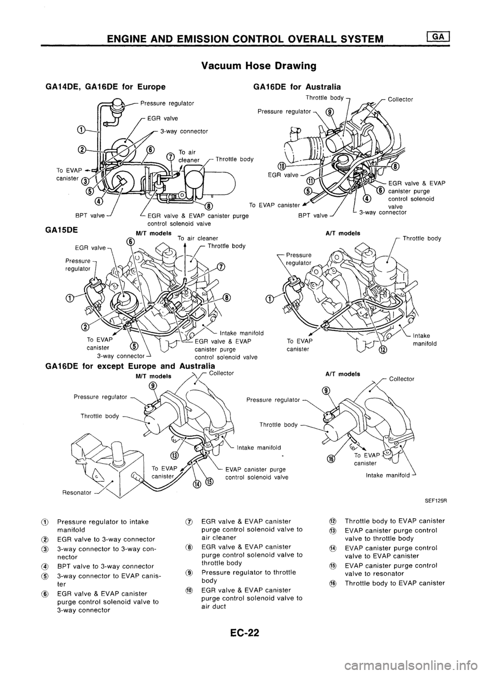
ENGINEANDEMISSION CONTROLOVERALLSYSTEM
Vacuum HoseDrawing
GA 14DE, GA16DE forEurope
GA15DE
Pressureregulator ~.
"
Throttle body
\1--"
10 ~
EGR valve
~L/
~1 ~
t~:::-
EGRvalve
&
EVAP
z:
0
5
I
L
W
canister purge
4
controlsolenoid
8 ToEVAP canister
¥
valve
EGR valve &EVAP canister purge BPTvalve 3-wayconnector
control solenoid valve
MIT
models
AIT
models
AIT
models
SEF125R
(1)
Pressure regulator tointake
manifold
@ EGR valve to3-way connector
@ 3-way connector to3-way con-
nector
@ BPTvalve to3-way connector
@
3-way connector toEVAP canis-
ter
@ EGR valve
&
EVAP canister
purge control solenoid valveto
3-way connector
(j)
EGR valve
&
EVAP canister
purge control solenoid valveto
air cleaner
@ EGRvalve
&
EVAP canister
purge control solenoid valveto
throttle body
@
Pressure regulator tothrottle
body
@l
EGR valve
&
EV AP canister
purge control solenoid valveto
air duct
EC-22 @
Throttle bodytoEVAP canister
@ EVAP canister purgecontrol
valve tothrottle body
@ EVAP canister purgecontrol
valve toEVAP canister
@ EVAP canister purgecontrol
valve toresonator
@
Throttle bodytoEVAP canister
Page 742 of 1701
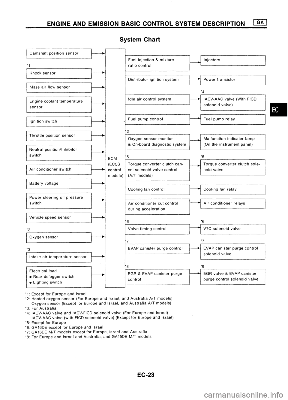
ENGINEANDEMISSION BASICCONTROL SYSTEMDESCRIPTION
System Chart
I
Camshaft positionsensor
'1
Fuel
injection
&
mixture
ratio control Injectors
Knock sensor
Distributorignitionsystem Powertransistor
Mass airflow sensor
Engine coolant temperature
sensor
Ignition switch Idle
aircontrol system
Fuel pump control
*4
IACV-AAC valve(WithFICD
solenoid valve)
Fuel pump relay
•
'5
Throttle
positionsensor
Neutral positionllnhibitor
switch
Air conditioner switch ECM
(ECCS
control
module)
2
Oxygen sensormonitor
&
On-board diagnostic system
5
Torque converter clutchcan-
cel solenoid valvecontrol
(A/T models) Malfunction
indicatorlamp
(On theinstrument panel)
Torque converter clutchsole-
noid valve
VTC solenoid valve
*6
Air
conditioner relays
Cooling
fanrelay
EVAP canister purgecontrol
solenoid valve
Cooling
fancontrol
Air conditioner cutcontrol
during acceleration
Valve timing control
EVAP canister purgecontrol
7
6
Power
steering oilpressure
switch Battery
voltage
Intake airtemperature sensor
*3
I
Vehicle speedsensor
*2
I
Oxygen sensor
8
'8
Electrical load
• Rear defogger switch
• Lighting switch EGR
&
EVAP canister purge
control EGR
valve
&
EVAP canister
purge control solenoid valve
*1: Except forEurope andIsrael
*2: Heated oxygen sensor(ForEurope andIsrael, andAustralia A/Tmodels)
Oxygen sensor(Except forEurope andIsrael, andAustralia A/Tmodels)
*3: For Australia
*4: IACV-AAC valveandIACV-FICD solenoidvalve(ForEurope andIsrael)
IACV-AAC valve(withFICDsolenoid valve)(Except forEurope andIsrael)
'5: Except forEurope
*6: GA16DE exceptforEurope andIsrael
*7: GA16DE MITmodels exceptforEurope, IsraelandAustralia
*8: For Europe andIsrael andAustralia, andGA15DE MITmodels
EC-23
Page 748 of 1701
EVAPORATIVEEMISSIONSYSTEM
•
SEF126R
EVAP
canister
'1
EVAP canister
purge control
solenoid valve
or
'2 EGR valve
&
EVAP canister
purge control
solenoid
valve To
EGR
I
valve
I
,
I
1
1
I
I
I
Vacuum :
signal line I
I
I
I
I
I
I
-- -- --- -- ------ __....J
r---
------- -------- ---------,
Fuel fillercap
with vacuum
relief valve
------------,
I
I
I
I
I
I
I
I
I
I
I
'-
Throttle
valve~
I
Fuel check valve
Intake
manifold
'1 :GA 16DE M/Tmodels exceptforEurope,
Israel andAustralia
'2 :For Europe, IsraelandAustralia,
and GA15DE
M/T
models
~ :GA 15, 16DE AlTmodels exceptfor
Europe, IsraelandAustralia
.. :Air
Q :
Fuel vapor
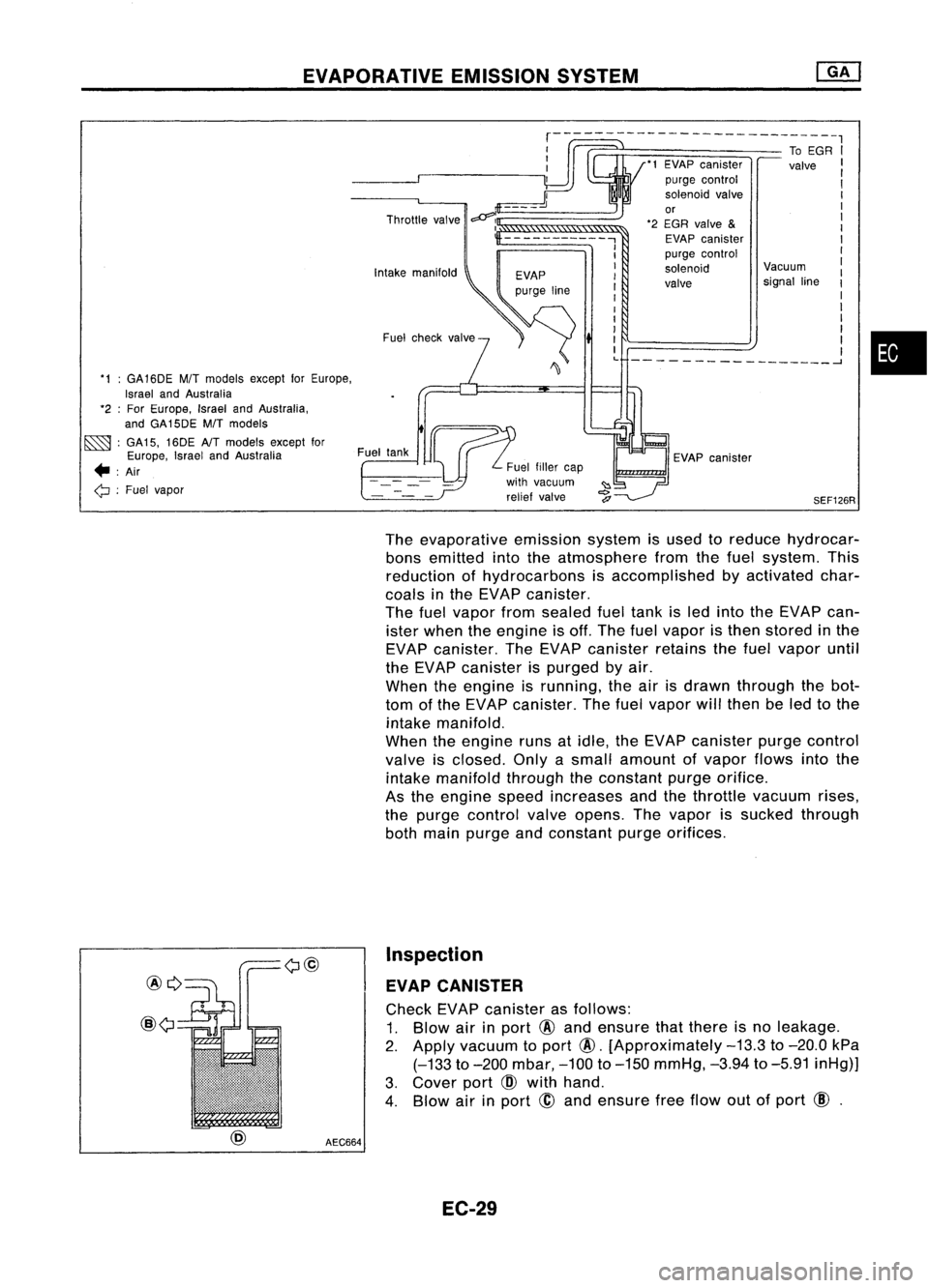
Theevaporative emissionsystemisused toreduce hydrocar-
bons emitted intotheatmosphere fromthefuel system. This
reduction ofhydrocarbons isaccomplished byactivated char-
coals inthe EVAP canister.
The fuelvapor fromsealed fueltank isled into theEVAP can-
ister when theengine isoff. The fuelvapor isthen stored inthe
EVAP canister. TheEVAP canister retainsthefuel vapor until
the EVAP canister ispurged byair.
When theengine isrunning, theairisdrawn through thebot-
tom ofthe EVAP canister. Thefuel vapor willthen beled tothe
intake manifold.
When theengine runsatidle, theEVAP canister purgecontrol
valve isclosed. Onlyasmall amount ofvapor flowsintothe
intake manifold throughtheconstant purgeorifice.
As the engine speedincreases andthethrottle vacuum rises,
the purge control valveopens. Thevapor issucked through
both main purge andconstant purgeorifices.
@Q
@
AEC664Inspection
EVAP CANISTER
Check EVAPcanister asfollows:
1. Blow airinport
@
and ensure thatthere isno leakage.
2.
Apply vacuum toport
@.
[Approximately
-13.3
to
-20.0
kPa
(-133
to
-200
mbar,
-100
to
-150
mmHg,
-3.94
to
-5.91
inHg)]
3. Cover port
CID
with hand.
4. Blow airinport
@
and ensure freeflow outofport
CID.
EC-29