1995 NISSAN ALMERA N15 ECO mode
[x] Cancel search: ECO modePage 767 of 1701
ON-BOARDDIAGNOSTIC SYSTEMDESCRIPTION
for
CONSULT
E3==/
NISSAN
CONSULT
EE940
+
I !DiI
I
START
I
SUB
MODE
I
SEF253Q
~ SELECT~S_Y_S_T_EM
I
ENGINE----~
SEFS95K
~ SELECT DIAGMODE
lill
WORK SUPPORT
I
SELF-DIAG RESULTS
I
DATA MONITOR
I
ACTIVE TEST
I
ECM PART NUMBER
I
FUNCTION TEST
SEF136PCONSULT
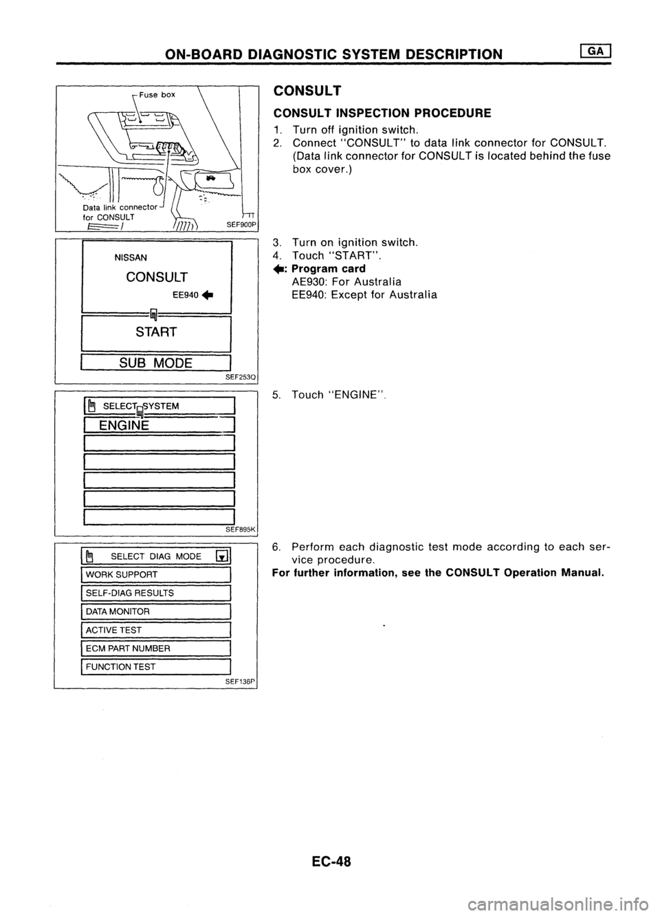
CONSULT INSPECTION PROCEDURE
1. Turn offignition switch.
2. Connect "CONSULT" todata linkconnector forCONSULT.
(Data linkconnector forCONSULT islocated behindthefuse
box cover.)
3. Turn onignition switch.
4. Touch "START".
+:
Program card
AE930: ForAustralia
EE940: ExceptforAustralia
5. Touch "ENGINE".
6. Perform eachdiagnostic testmode according toeach ser-
vice procedure.
For further information, seetheCONSULT OperationManual.
EC-48
Page 768 of 1701
ON-BOARDDIAGNOSTIC SYSTEMDESCRIPTION
CONSULT (Cont'd)
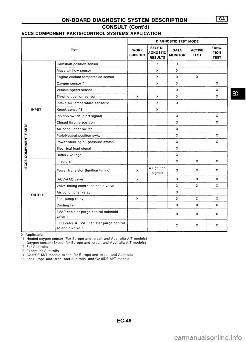
ECCS COMPONENT PARTS/CONTROL SYSTEMSAPPLICATION
DIAGNOSTICTESTMODE
Item WORKSELF-DI-
ACTIVEFUNC-
DATA
SUPPORT AGNOSTIC
MONITOR TION
TEST
RESULTS TEST
Camshaft positionsensor
X
X
Mass airflow sensor
X
X
Engine coolant temperature sensor
X
X X
Oxygen sensor'1
X
X X
Vehicle speedsensor
XX
Throttle positionsensor
XX
X X
Intake airtemperature sensor.'2
X
X
INPUT
Knock
sensor'3
X
Ignition switch(startsignal)
XX
I/)
Closed
throttle position
X
X
l-
ll:
Airconditioner switch
X
<
~
Park/Neutralpositionswitch
X
X
I-
Z
UJ
Powersteering oilpressure switch
XX
z
0
Electricalloadsignal
X
~
:E
0
Batteryvoltage
X
u
I/)
Injectors
XX
X
u
u
UJ
X(Ignition
Power transistor (Ignitiontiming) X X
XX
signal)
IACV-AAC valve X
XX
X
Valve timing control solenoid valve XX
X
OUTPUT
Air
conditioner relay
X
Fuel pump relay XX
XX
Cooling fan XX
X
EVAP canister purgecontrol solenoid
XX X
valve'4
EGR valve
&
EVAP canister purgecontrol
XX
X
solenoid valve'5
X: Applicable
'1: Heated oxygen sensor(ForEurope andIsrael, andAustralia AITmodels)
Oxygen sensor(Except forEurope andIsrael, andAustralia AITmodels)
'2: For Australia
'3: Except forAustralia
'4: GA16DE
MIT
models exceptforEurope andIsrael, andAustralia
'5: For Europe andIsrael andAustralia, andGA15DE
MIT
models
EC-49
•
Page 770 of 1701
ON-BOARDDIAGNOSTIC SYSTEMDESCRIPTION
CONSULT (ConI'd)
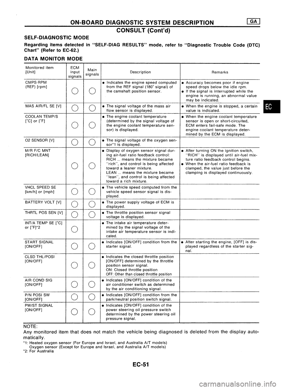
SELF-DIAGNOSTIC MODE
Regarding itemsdetected in"SELF-DIAG RESULTS"mode,referto"Diagnostic TroubleCode(DTC)
Chart" (RefertoEC-62.)
DATA MONITOR MODE
Monitored item ECM
Main
[Unit] input
signals Description
Remarks
signals
CMPS.RPM •Indicates theengine speedcomputed •Accuracy becomespoorifengine
(REF) [rpm]
00
from
theREF signal (180'signal) of
speeddropsbelow theidle rpm.
the camshaft positionsensor.
•Ifthe signal isinterrupted whilethe
engine isrunning, anabnormal value
may beindicated .
MAS AIR/FL SE[V]
0 0
•
The signal voltage ofthe mass air
•When theengine isstopped, acertain
flow sensor isdisplayed .
valueisindicated.
COOLAN TEMP/S
•The engine coolant temperature •When theengine coolant temperature
['C] or['F]
00
(determined
bythe signal voltage of
sensorisopen orshort-circuited,
the engine coolant temperature sen-ECMenters fail-safe mode.The
sor) isdisplayed.
enginecoolant temperature deter-
mined bythe ECM isdisplayed .
02 SENSOR [V]
00
•
The signal voltage ofthe oxygen sen-
sor*1 isdisplayed .
M/R F/CMNT •
Display ofoxygen sensorsignaldur-
•After turning ONthe ignition switch,
[RICH/LEAN] ingair-fuel ratiofeedback control: "RICH"isdisplayed untilair-fuel mix-
RICH ...means themixture became
tureratio feedback controlbegins.
0 0
"rich",
andcontrol isbeing affected •When theair-fuel ratiofeedback is
toward aleaner mixture.
clamped,thevalue justbefore the
LEAN ...means themixture became clampingisdisplayed continuously.
"lean", andcontrol isbeing affected
toward arich mixture .
VHCL SPEED SE
00
•
The vehicle speedcomputed fromthe
[km/h] or[mph] vehicle
speedsensor signalisdis-
played .
BATTERY VOLT[V]
0 0
•
The power supply voltage ofECM is
displayed .
THRTL POSSEN[V]
0 0
•
The throttle position sensorsignal
voltage isdisplayed.
INT/A TEMP SE['C] •The intake airtemperature deter-
or ['F]*2
0
mined
bythe signal voltage ofthe
intake airtemperature sensorisindi-
cated .
START SIGNAL
00
•
Indicates [ON/OFF] conditionfromthe•After starting theengine, [OFF]isdis-
[ON/OFF] startersignal. playedregardless ofthe starter sig-
nal.
CLSD THLIPOSI •Indicates theclosed throttle position
[ON/OFF]
00
[ON/OFF]
determined bythe throttle
position sensorsignal.
ON: Closed throttle position
OFF: Other thanclosed throttle position
AIR COND SIG
00
•
Indicates [ON/OFF] conditionofthe
[ON/OFF] air
conditioner switchasdetermined
by the airconditioning signal.
PIN POSI SW
00
•
Indicates [ON/OFF] conditionfromthe
[ON/OFF] park/neutralpositionswitchsignal.
PW/ST SIGNAL •
Indicates [ON/OFF] conditionofthe
[ON/OFF]
00
power
steering oilpressure switch
determined bythe power steering oil
pressure signal.
NOTE:
Any monitored itemthatdoes notmatch thevehicle beingdiagnosed isdeleted fromthedisplay auto-
matically.
*1: Heated oxygen sensor(ForEurope andIsrael, andAustralia A/Tmodels)
Oxygen sensor(Except forEurope andIsrael, andAustralia A/Tmodels)
*2: For Australia
EC-51
•
Page 771 of 1701
![NISSAN ALMERA N15 1995 Service Manual ON-BOARDDIAGNOSTIC SYSTEMDESCRIPTION
CONSULT (Coni'd)
Monitored item
ECM
Main
[Unit] input
signals Description
Remarks
signals
LOAD SIGNAL •Indicates [ON/OFF] conditionfromthe
[ON/OFF] reardefo NISSAN ALMERA N15 1995 Service Manual ON-BOARDDIAGNOSTIC SYSTEMDESCRIPTION
CONSULT (Coni'd)
Monitored item
ECM
Main
[Unit] input
signals Description
Remarks
signals
LOAD SIGNAL •Indicates [ON/OFF] conditionfromthe
[ON/OFF] reardefo](/manual-img/5/57349/w960_57349-770.png)
ON-BOARDDIAGNOSTIC SYSTEMDESCRIPTION
CONSULT (Coni'd)
Monitored item
ECM
Main
[Unit] input
signals Description
Remarks
signals
LOAD SIGNAL •Indicates [ON/OFF] conditionfromthe
[ON/OFF] reardefogger signaland/or lighting
switch.
0 0
ON:
Rear defogger isoperating
and/or lighting switchison.
OFF: Rear defogger isnot operating
and lighting switchisnot on.
INJ PULSE [msec]
0
•
Indicates theactual fuelinjection
•When theengine isstopped, acertain
pulse widthcompensated byECM computedvalueisindicated.
according tothe input signals.
IGN TIMING [BTDC]
0
•
Indicates theignition timingcomputed
by ECM according tothe input sig-
nals.
IACV-AACIV
[%]
•Indicates theidle aircontrol valve
0
(AAC
valve) control valuecomputed
by ECM according tothe input sig-
nals.
A/F ALPHA
[%]
•Indicates themean valueofthe air-
•When theengine isstopped, acertain
0
fuel
ratio feedback correction factor valueisindicated.
per cycle. •This data alsoincludes thedata for
the air-fuel ratiolearning control.
AIR COND RLY
0
•
Indicates theairconditioner relay
[ON/OFF] controlcondition (determined byECM
according tothe input signal).
COOLING FAN*2
•Indicates thecontrol condition ofthe
[ON/OFF] or[LOW/
coolingfans(determined byECM
HI/OFF]
0
according
tothe input signal).
ON ...Operating
LOW ...Operates atlow speed
HI ...Operates athigh speed
OFF ...Stopped
FUEL PUMP RLY
0
•
Indicates thefuel pump relaycontrol
[ON/OFF] conditiondetermined byECM accord-
ing tothe input signals.
VALVE TIMSOL*1
•The control condition ofthe valve tim-
[ON/OFF] ingsolenoid valve(determined by
ECM according tothe input signal) is
indicated.
ON ...VTC operating
OFF ...VTC notoperating
EGRC SOLIV (EVAP
•Indicates thecontrol condition ofthe
canister purgecon-
EVAPcanister purgecontrol solenoid
trol solenoid valve valveorEGR valve
&
EVAP canister
or EGR
&
EVAP can- purgecontrol solenoid valve(deter-
ister purge control
0
mined
byECM according tothe input
solenoid valve) signal).
[ON/OFF] ON'"EVAP canister purgeoperation
cut-off OFF ...EVAP canister purgeoperation
not cut-off
VOLTAGE •Voltage measured bythe voltage
[V] probe.
PULSE •Pulse width, frequency orduty cycle •Only "#"isdisplayed ifitem is
[msec] or[Hz] or measuredbythe pulse probe. unable
tobe measured .
[%]
•
Figures with"#"s aretemporary
ones. Theyarethesame figures as
an actual pieceofdata which wasjust
previously measured.
*1: GA16DE exceptforEurope andIsrael
*2: GA16DE engineA/Tmodels forEurope without heavydutykithave a2- step control [ON/OFF] system."LOW"and"HI"
are shown onCONSULT screentorepresent "ON"condition.
EC-52
Page 772 of 1701

ON-BOARDDIAGNOSTIC SYSTEMDESCRIPTION
CONSULT (Cont'd)
ACTIVE TESTMODE
TEST ITEM CONDITION JUDGEMENT
CHECKITEM(REMEDY)
• Engine: Returntothe original
•Harness andconnector
FUEL INJECTION trouble
condition If
trouble symptom disappears,
•Fuel injectors
• Change theamount offuel see
CHECK ITEM.
injection usingCONSULT . •
Oxygen sensor*1
• Engine: Afterwarming up,idle
IACV-AACIV the
engine.
Enginespeedchanges according •Harness andconnector
OPENING •
Change theIACV-AAC valve
tothe opening percent. •
IACV-AAC valve
opening percentusingCON-
SULT.
• Engine: Returntothe original
•Harness andconnector
ENG COOLANT trouble
condition
Iftrouble symptom disappears, •
Engine coolant temperature
TEMP •
Change theengine coolant
.
see CHECK ITEM. sensor
temperature indicationusing
•Fuel injectors
CONSULT.
• Engine: Returntothe original
trouble condition
Iftrouble symptom disappears,
IGNITION TIMING•
Timing light:Set •
Adjust initialignition timing
• Retard theignition timingusingsee
CHECK ITEM.
CONSULT .
• Engine: Afterwarming up,idle •
Harness andconnector
the engine. •
Compression
POWER •
A/C switch "OFF"
Enginerunsrough ordies . •
Injectors
BALANCE •
Shift lever "N" •
Power transistor
• Cut offeach injector signalone •
Spark plugs
at atime using CONSULT. •
Ignition coils
• Ignition switch:ON
COOLING FAN*3•
Turn thecooling fan"ON" and
Cooling fanmoves andstops. •
Harness andconnector
"OFF", or"LOW" and"HI" •
Cooling fanmotor
and "OFF" usingCONSULT .
• Ignition switch:ON(Engine
FUEL PUMP stopped)
Fuelpump relaymakes theoper- •Harness andconnector
• Turn thefuel pump relay"ON"
RELAY and"OFF" usingCONSULT ating
sound. •
Fuel pump relay
and listen tooperating sound.
EGRC SOLENOID
VALVE (EVAP canister
•Ignition switch:ON
purge control
•Turn solenoid valve"ON" and Solenoid
valvemakes anoperat- •
Harness andconnector
solenoid valveor
EGR valve
&
"OFF"
withtheCONSULT andingsound. •
Solenoid valve
EVAP canister listen
tooperating sound.
purge control
solenoid valve)
•Ignition switch:ON
VALVE TIMING •
Turn solenoid valve"ON" and Solenoid
valvemakes anoperat- •
Harness andconnector
SOL*2 "OFF"
usingCONSULT anding
sound. •
Solenoid valve
listen tooperating sound.
SELF-LEARNING •
Inthis test, thecoefficient ofself-learning controlmixture ratioreturns tothe original coefficient by
CONT touching
"CLEAR" onthe screen.
*1: Heated oxygen sensor(ForEurope andIsrael, andAustralia A/Tmodels)
Oxygen sensor(Except forEurope andIsrael, andAustralia A/Tmodels)
*2: GA16DE except forEurope andIsrael
*3: GA16DE engine A/Tmodels forEurope without heavydutykithave a2- step control [ON/OFF] system."LOW"and"HI"
are shown onCONSULT screentorepresent "ON"condition.
EC-53
•
Page 773 of 1701
ON-BOARDDIAGNOSTIC SYSTEMDESCRIPTION
CONSULT (Cont'd)
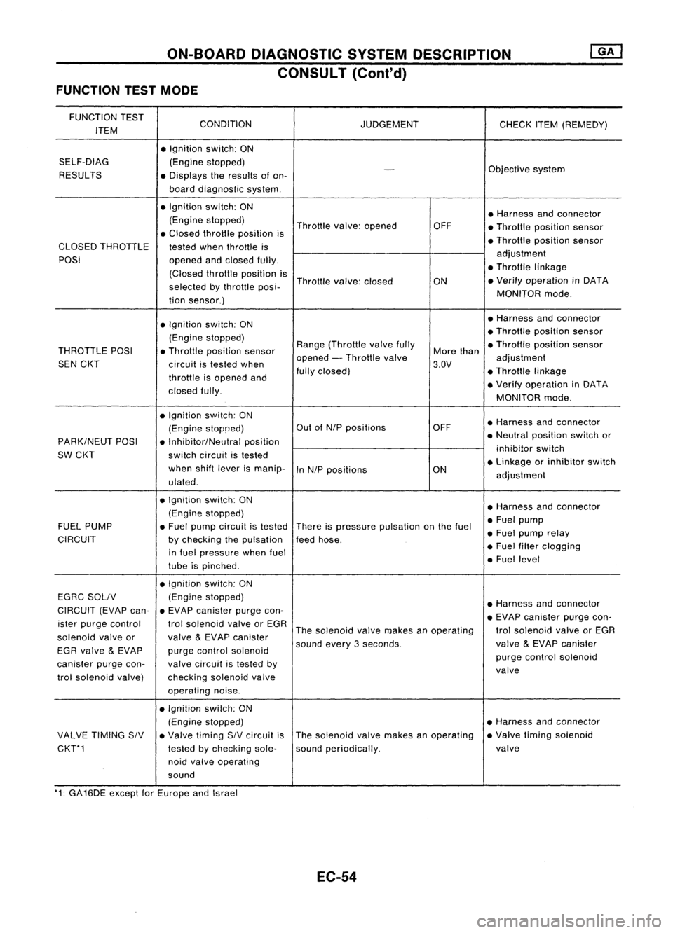
FUNCTION TESTMODE
FUNCTION TEST
CONDITION
ITEM JUDGEMENT
CHECKITEM(REMEDY)
• Ignition switch:ON
SELF-DIAG (Enginestopped)
RESULTS
-
Objective
system
• Displays theresults ofon-
board diagnostic system.
• Ignition switch:ON
•Harness andconnector
(Engine stopped)
Throttlevalve:opened OFF
•Throllle position sensor
• Closed throllle position is
•Throllie position sensor
CLOSED THROTTLE
testedwhenthrottle is
POSI openedandclosed fully. adjustment
(Closed throllieposition is •
Throttle linkage
selected bythrottle posi- Throttle
valve:closed
ON•
Verify operation inDATA
tion sensor.) MONITOR
mode.
• Ignition switch:ON •
Harness andconnector
(Engine stopped) •
Throttle position sensor
THROTTLE POSI•Throllle position sensor Range
(Throllle valvefully
Morethan •
Throllle position sensor
SEN CKT
circuitistested when opened
-Throllle valve
3.DV adjustment
throllie isopened and fully
closed) •Throllie linkage
closed fully. •
Verify operation inDATA
MONITOR mode.
• Ignition switch:ON
•Harness andconnector
(Engine stopoed) Out
ofNIP positions OFF
PARK/NEUT POSI
•Inhibitor/NelJlral position •
Neutral position switchor
SW CKT switchcircuit istested inhibitor
switch
when shiftlever ismanip-
InNIP positions ON•
Linkage orinhibitor switch
ulated . adjustment
• Ignition switch:ON
•Harness andconnector
(Engine stopped)
•Fuel pump
FUEL PUMP •Fuel pump circuit istested
Thereispressure pulsation onthe fuel
•Fuel pump relay
CIRCUIT bychecking thepulsation feedhose.
in fuel pressure whenfuel •
Fuel filter clogging
tube ispinched . •
Fuel level
• Ignition switch:ON
EGRC SOllV (Engine
stopped)
•Harness andconnector
CIRCUIT (EVAPcan-•EVAP canister purgecon-
•EVAP canister purgecon-
ister purge control trolsolenoid valveorEGR
Thesolenoid valvemakes anoperating trolsolenoid valveorEGR
solenoid valveor
valve
&
EVAP canister
soundevery3seconds. valve
&
EVAP canister
EGR valve
&
EVAP purgecontrol solenoid
purgecontrol solenoid
canister purgecon- valvecircuit istested by
valve
trol solenoid valve) checkingsolenoidvalve
operating noise.
• Ignition switch:ON
(Engine stopped) •
Harness andconnector
VALVE TIMING SIV•Valve timing SIVcircuit isThe
solenoid valvemakes anoperating •
Valve timing solenoid
CKT*1 testedbychecking sole-soundperiodically. valve
noid valve operating
sound
'1: GA16DE exceptforEurope andIsrael
EC-54
Page 774 of 1701
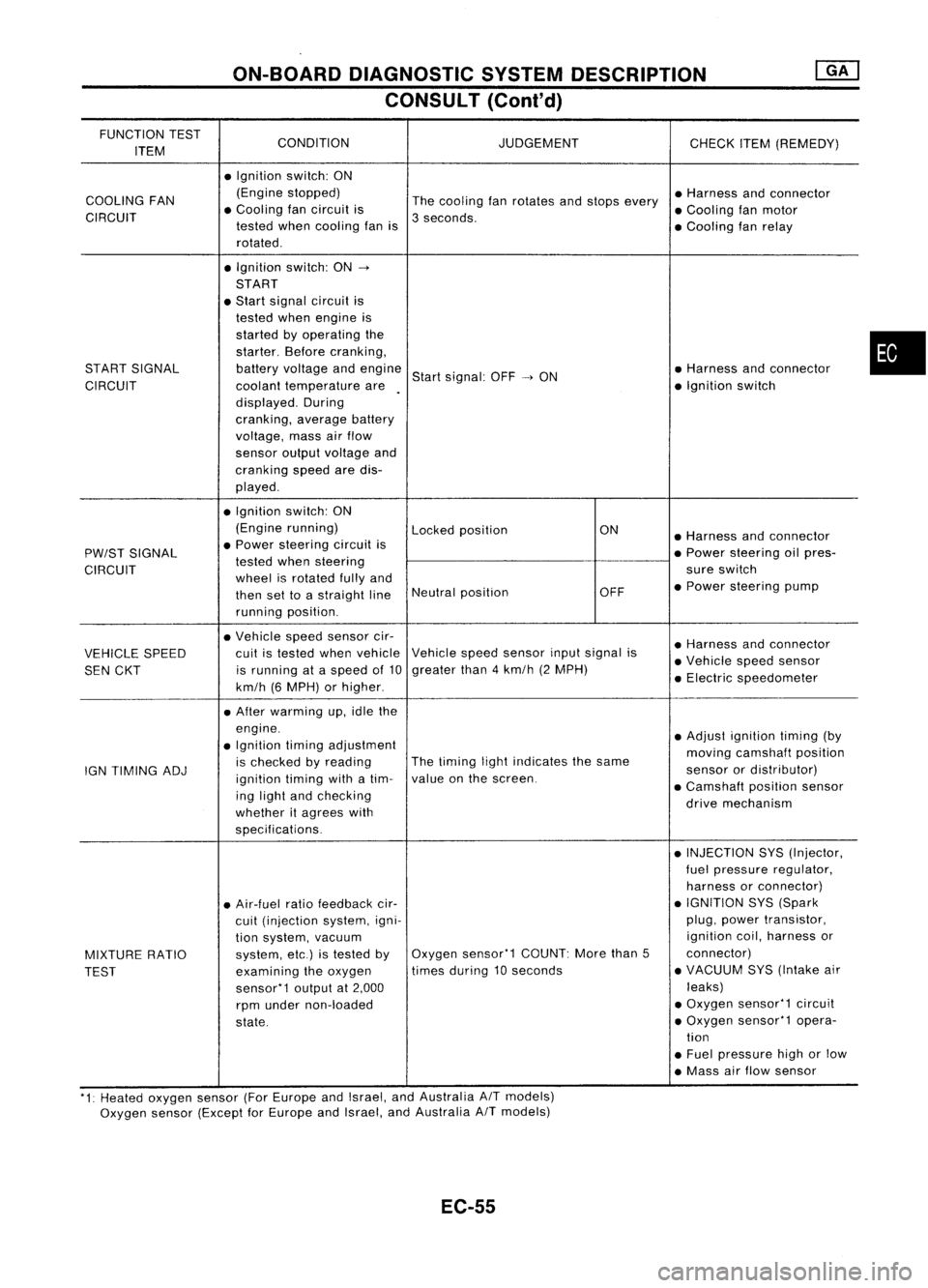
ON-BOARDDIAGNOSTIC SYSTEMDESCRIPTION
CONSULT (Conl'd)
FUNCTION TEST
CONDITION JUDGEMENT
ITEM CHECK
ITEM(REMEDY)
• Ignition switch:ON
COOLING FAN (Engine
stopped)
Thecooling fanrotates andstops every •
Harness andconnector
CIRCUIT •
Cooling fancircuit is
3seconds. •
Cooling fanmotor
tested whencooling fanis
•Cooling fanrelay
rotated .
• Ignition switch:ON-.
START
• Start signal circuit is
tested whenengine is
started byoperating the
starter. Beforecranking,
START SIGNAL batteryvoltage andengine
Startsignal: OFF-.ON •
Harness andconnector
CIRCUIT coolanttemperature are •
Ignition switch
displayed. During
cranking, averagebattery
voltage, massairflow
sensor outputvoltage and
cranking speedaredis-
played .
• Ignition switch:ON
(Engine running)
Lockedposition ON
•Harness andconnector
PW/ST SIGNAL •
Power steering circuitis
•Power steering oilpres-
tested whensteering
CIRCUIT wheelisrotated fullyand sure
switch
then settoastraight lineNeutral
position OFF•
Power steering pump
running position.
• Vehicle speedsensor cir-
•Harness andconnector
VEHICLE SPEED cuit
istested whenvehicle Vehicle
speedsensor inputsignal is
•Vehicle speedsensor
SEN CKT is
running ataspeed of10 greater
than4km/h (2MPH)
•Electric speedometer
km/h (6MPH) orhigher .
• After warming up,idle the
engine. •Adjust ignition timing(by
• Ignition timingadjustment
movingcamshaft position
IGN TIMING ADJ is
checked byreading The
timing lightindicates thesame
sensorordistributor)
ignition timingwithatim- value
onthe screen.
•Camshaft positionsensor
ing light andchecking
drivemechanism
whether itagrees with
specifications.
•INJECTION SYS(Injector,
fuel pressure regulator,
harness orconnector)
• Air-fuel ratiofeedback cir- •
IGNITION SYS(Spark
cuit (injection system,igni- plug,
power transistor,
tion system, vacuum ignition
coil,harness or
MIXTURE RATIO system,
etc.)istested byOxygen
sensor'1 COUNT:Morethan5 connector)
TEST examining
theoxygen times
during 10seconds •
VACUUM SYS(Intake air
sensor'1 outputat2,000 leaks)
rpm under non-loaded •
Oxygen sensor'1 circuit
state. •
Oxygen sensor'1 opera-
tion
• Fuel pressure highorlow
• Mass airflow sensor
'1: Heated oxygen sensor(ForEurope andIsrael, andAustralia AITmodels)
Oxygen sensor(Except forEurope andIsrael, andAustralia
A/T
models)
EC-55
•
Page 776 of 1701
![NISSAN ALMERA N15 1995 Service Manual ON-BOARDDIAGNOSTIC SYSTEMDESCRIPTION
[]K]
CONSULT (Cont'd)
REAL TIMEDIAGNOSIS INDATA MONITOR MODE
CONSULT hastwo kinds oftriggers andthey canbeselected bytouching "SETTING" in"DATA
NISSAN ALMERA N15 1995 Service Manual ON-BOARDDIAGNOSTIC SYSTEMDESCRIPTION
[]K]
CONSULT (Cont'd)
REAL TIMEDIAGNOSIS INDATA MONITOR MODE
CONSULT hastwo kinds oftriggers andthey canbeselected bytouching "SETTING" in"DATA](/manual-img/5/57349/w960_57349-775.png)
ON-BOARDDIAGNOSTIC SYSTEMDESCRIPTION
[]K]
CONSULT (Cont'd)
REAL TIMEDIAGNOSIS INDATA MONITOR MODE
CONSULT hastwo kinds oftriggers andthey canbeselected bytouching "SETTING" in"DATA
MONITOR" mode.
1. "AUTO TRIG"(Automatic trigger):
• The malfunction willbeidentified onthe CONSULT screeninreal time.
In other words, DTCandmalfunction itemwillbedisplayed atthe moment themalfunction is
detected byECM.
DATA MONITOR canbeperformed continuously untilamalfunction isdetected. However, DATA
MONITOR cannotcontinue anylonger afterthemalfunction detection.
2. "MANU TRIG"(Manual trigger):
• DTC andmalfunction itemwillnotbedisplayed automatically onCONSULT screeneventhough
a malfunction isdetected byECM. •
DATA MONITOR canbeperformed continuously eventhough amalfunction isdetected.
Use these triggers asfollows:
1. "AUTO TRIG"
• While trying todetect theDTC byperforming the"DTC CONFIRMATION PROCEDURE",besure
to select to"DATA MONITOR (AUTOTRIG)" mode.Youcanconfirm themalfunction atthe
moment itis detected.
• While narrowing downthepossible causes,CONSULT shouldbeset in"DATA MONITOR (AUTO
TRIG)" mode,especially incase theincident isintermittent.
Inspect thecircuit bygently shaking (ortwisting) suspicious connectors, components andharness
in the "DTC CONFIRMATION PROCEDURE".Themoment amalfunction isfound theDTC willbe
displayed. (RefertoGI section, "Incident Simulation Tests"in"HOW TOPERFORM EFFICIENT
DIAGNOSIS FORANELECTRICAL INCIDENT".)
2. "MANU TRIG"
• Ifthe malfunction isdisplayed assoon as"DATA MONITOR" isselected, resetCONSULT to
"MANU TRIG".Byselecting "MANUTRIG"youcanmonitor andstore thedata. Thedata canbe
utilized forfurther diagnosis, suchasacomparison withthevalue forthe normal operating con-
dition.
HISPEED
AUTO
TRIG
I
~
SELECT MONITOR ITEM
ECM INPUT SIGNALS
MAIN SIGNALS
SELECTION FROMMENU
I
~
SET RECORDING COND
I
MANU TRIG
I
LONG TIME HI
SPEED MANU
TRIG
SETTING
II
START
___ 1__ 1
"SETTIN-G" "AUTOTRIG"
A
malfunction canbe
displayed on"DATA
MONITOR" screen
automatically ifdetected.
EC-57 "MANU
TRIG"
A malfunction cannotbe
displayed on"DATA
MONITOR" screen
automatically evenif
detected.
SEF674Q