1995 NISSAN ALMERA N15 ECO mode
[x] Cancel search: ECO modePage 843 of 1701
TROUBLEDIAGNOSIS FOROTC41
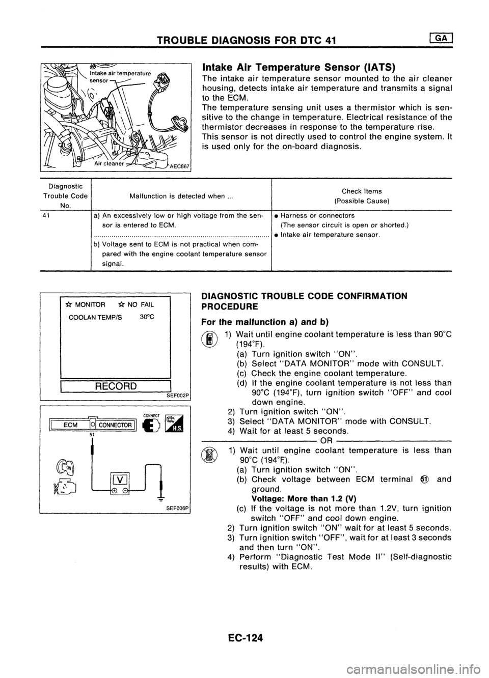
Intake AirTemperature Sensor(IATS)
The intake airtemperature sensormounted tothe aircleaner
housing, detectsintakeairtemperature andtransmits asignal
to the ECM.
The temperature sensingunituses athermistor whichissen-
sitive tothe change intemperature. Electricalresistance ofthe
thermistor decreases inresponse tothe temperature rise.
This sensor isnot directly usedtocontrol theengine system. It
is used onlyforthe on-board diagnosis.
Diagnostic
Trouble Code
No.
41
Malfunction
isdetected when...
a) An excessively loworhigh voltage fromthesen-
sor isentered toECM.
b) Voltage senttoECM isnot practical whencom-
pared withtheengine coolant temperature sensor
signal. Check
Items
(Possible Cause)
• Harness orconnectors
(The sensor circuitisopen orshorted.)
• Intake airtemperature sensor.
*
MONITOR
*
NO FAIL
COOLAN TEMP/S 30°C
RECORD
I
SEF002P
CONNECT ~
II
ECM
a
CONNECTOR
II
I) ~
51
SEF006PDIAGNOSTIC
TROUBLECODECONFIRMATION
PROCEDURE
For themalfunction a)and b)
fF.I\
1)Wait untilengine coolant temperature isless than 90°C
~ (194°F).
(a) Turn ignition switch"ON".
(b) Select "DATA MONITOR" modewithCONSULT.
(c) Check theengine coolant temperature.
(d) Ifthe engine coolant temperature isnot less than
90°C (194°F), turnignition switch"OFF"andcool
down engine.
2) Turn ignition switch"ON".
3) Select "DATA MONITOR" modewithCONSULT.
4) Wait foratleast 5seconds.
---------OR ---------
~ 1)Wait untilengine coolant temperature isless than
~ 90°C(194°F.).
(a) Turn ignition switch"ON".
(b) Check voltage between ECMterminal
@
and
ground.
Voltage: Morethan1.2(V)
(c) Ifthe voltage isnot more than1.2V, turnignition
switch "OFF"andcool down engine.
2) Turn ignition switch"ON"waitforatleast 5seconds.
3) Turn ignition switch"OFF", waitforatleast 3seconds
and then turn"ON".
4) Perform "Diagnostic TestMode II"(Self-diagnostic
results) withECM.
EC-124
Page 855 of 1701
TROUBLEDIAGNOSIS FORNON-DETECTABLE ITEMS
@!J
Vehicle SpeedSensor (VSS)(Conl'd)
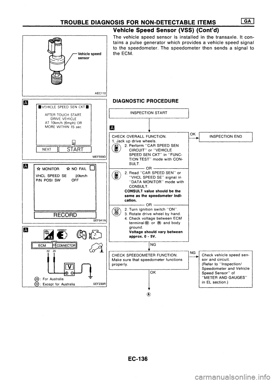
The vehicle speedsensor isinstalled inthe transaxle. Itcon-
tains apulse generator whichprovides avehicle speedsignal
to the speedometer. Thespeedometer thensends asignal to
Vehicle speed theECM.
sensor
AEC110 DIAGNOSTIC PROCEDURE
.V~HICLE SPEEDSENCKT.
AFTER TOUCH START.
DRIVE VEHICLE
AT 10km/h (6mph)OR
MORE WITHIN 15
see
INSPECTION
START
SEF941N
-(;(
NO FAIL
0
fijf.....
CONNECT
fIr:J:J:.~
1A1£) ~~
ECM
19'
CONNECTOR
II~
32 26
~l
INSPECTION
END
Check vehicle speedsen-
sor and circuil.
(Refer to"Inspectionl
Speedometer andVehicle
Speed Sensor" of
"METER ANDGAUGES"
in EL section.)
OK
NG
OK
NG
CHECK SPEEDOMETER FUNCTION.
Make surethatspeedometer functions
properly.
CHECK
OVERALL FUNCTION.
1. Jack updrive wheels.
(ij\
2.Perform "CARSPEED SEN
~ CIRCUIT" or"VEHICLE
SPEED SENCKT'" in"FUNC-
TION TEST'" modewithCON-
SULT OR
2. Read "CAR SPEED SEN"'or
"VHCL SPEED SE"signal in
"DATA MONITOR" modewith
CONSULT.
CONSULT valueshould bethe
same asthe speedometer indi-
cation. OR
2. Turn ignition switch"ON".
3. Rotate drivewhe'el byhand.
4. Check voltage between ECM
terminal
@
or@ and body
ground.
Voltage shouldvarybetween
approx. 0-5V.
SEF230R
MEF559D
20km/h
OFF
RECORD
l----
__ ,~--'
-N-EX-T
-II
STA-RT-
-(;( MONITOR
VHCL SPEED SE
PIN POSI SW
@:
ForAustralia
@:
Except forAustralia
II
EC-136
Page 856 of 1701
TROUBLEDIAGNOSIS FORNON-DETECTABLE ITEMS
Vehicle SpeedSensor (VSS)(Cont'd)
m
Models withtachometer
II
ECM
@ :For Australia
@ :Except forAustralia
Models without tachometer
II
ECM
@
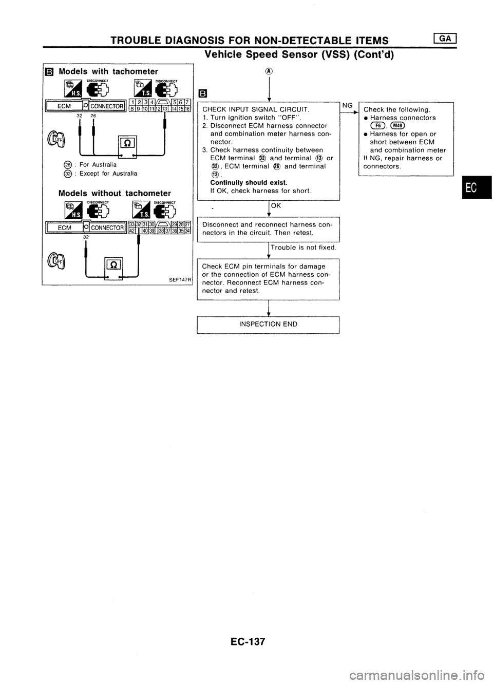
CHECK INPUTSIGNAL CIRCUIT.
1. Turn ignition switch"OFF".
2. Disconnect ECMharness connector
and combination meterharness con-
nector.
3. Check harness continuity between
ECM terminal
@
and terminal
@
or
@,
ECM terminal
@
and terminal
@.
Continuity shouldexist.
If OK, check harness forshort.
OK
Disconnect andreconnect harnesscon-
nectors inthe circuit. Thenretest.
Trouble isnot fixed.
NG
Check thefollowing.
• Harness connectors
GD,@
• Harness foropen or
short between ECM
and combination meter
If
NG, repair harness or
connectors.
•
SEF147R
Check
ECMpinterminals fordamage
or the connection ofECM harness con-
nector. Reconnect ECMharness con-
nector andretest.
INSPECTION END
EC-137
Page 859 of 1701
TROUBLEDIAGNOSIS FORNON-DETECTABLE ITEMS
Start Signal (Cont'd)
DIAGNOSTIC PROCEDURE
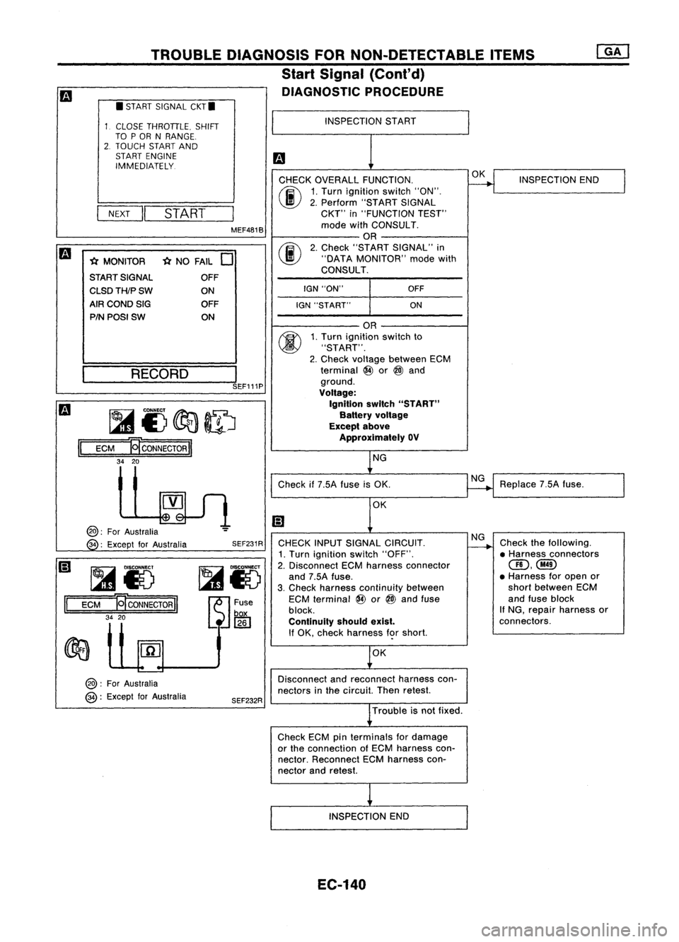
CHECK OVERALL FUNCTION.
00
1.
Turn ignition switch"ON".
I
II
2.
Perform "STARTSIGNAL
NEXT
START
CKT"
in"FUNCTION TEST"
MEF481B mode
withCONSULT.
OR
m
00
2.
Check "START SIGNAL" in
* MONITOR *
NO FAIL
0
"DATA
MONITOR" modewith
START SIGNAL CONSULT.
OFF
I
CLSDTH/PSW
ONIGN
"ON" OFF
AIR COND SIG OFF
IGN"START" ON
PIN POSI SW ON
II
•
START SIGNAL CKT.
CLOSE THROTTLE. SHIFT
TO POR NRANGE.
2. TOUCH STARTAND
START ENGINE
IMMEDIATELY.
~ __ RE_C_O_R_D_---,l
SEF111P
~I)~ID
ECM
B
CONNECTOR
II
34 20
INSPECTION
START
OR
1. Turn ignition switchto
"START".
2. Check voltage between ECM
terminal @or
@l
and
ground.
Voltage:
Ignition switch"START"
Battery voltage
Except above
Approximately OV
NG OK
INSPECTION END
II
@:
ForAustralia
34 :Except forAustralia
~Io
ECM
ET
CONNECTOR
II
34 20
@:
ForAustralia
@:
Except forAustralia SEF231R
SEF232R Check
if7.5A fuseisOK.
OK
CHECK INPUTSIGNAL CIRCUIT.
1. Turn ignition switch"OFF".
2. Disconnect ECMharness connector
and 7.5A fuse.
3. Check harness continuity between
ECM terminal @or
@l
and fuse
block.
Continuity shouldexist.
If OK, check harness f<;>rshort.
OK
Disconnect andreconnect harnesscon-
nectors inthe circuit. Thenretest.
Trouble isnot fixed.
Check ECMpinterminals fordamage
or the connection ofECM harness con-
nector. Reconnect ECMharness con-
nector andretest.
INSPECTION END
EC-140
NG
NG
Replace
7.5Afuse.
Check thefollowing.
• Harness connectors
(ID,@
• Harness foropen or
short between ECM
and fuse block
If NG, repair harness or
connectors.
Page 862 of 1701
•
INSPECTION END
Check thefollowing.
• Harness connectors
@,@or@,
@
• Harness connectors
@,CillD
• Harness foropen or
short between injector
and ignition switch
If NG, repair harness or
connectors.
OK
NG
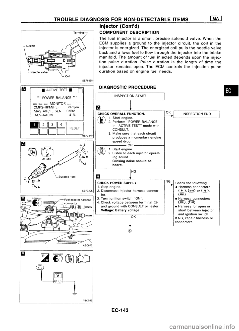
DIAGNOSTIC
PROCEDURE
INSPECTION START
CHECK OVERALL FUNCTION.
(F.I\
1.Start engine.
~ 2.Perform "POWER BALANCE"
in "ACTIVE TEST"modewith
CONSULT.
3. Make surethateach circuit
produces amomentary engine
speed drop.
OR
fff\
1.Start engine.
~ 2.Listen toeach injector operat-
ing sound.
Clicking noiseshould be
heard.
CHECK POWER SUPPLY.
1. Stop engine.
2. Disconnect injectorharness connec-
tor.
3. Turn ignition switch"ON".
4. Check voltage between terminal @
and ground withCONSULT ortester.
Voltage: Batteryvoltage
AEC872
SEF730L
/~~
Click
Ct.
'~.+
Fuel injector harness
connector
II
TROUBLE
DIAGNOSIS FORNON-DETECTABLE ITEMS
Injector (Cont'd)
COMPONENT DESCRIPTION
The fuel injector isasmall, precise solenoid valve.Whenthe
ECM supplies aground tothe injector circuit,thecoil
in
the
injector isenergized. Theenergized coilpulls theneedle valve
back andallows fueltoflow through theinjector intotheintake
manifold. Theamount offuel injected depends upontheinjec-
tion pulse duration. Pulseduration isthe length oftime the
injector remains open.TheECM controls theinjection pulse
duration basedonengine fuelneeds.
SEF596K
• ACTIVE TEST.
D
••• POWER BALANCE •••
= ==
MONITOR
=
==
CMPS.RPM(REF) 737rpm
MAS AIR/FL SEN098V
IACV-AAC/V 41%
110Q]Q]~
DDDDc:J
MEF354F
~7~
~ \)drJ
At idle
--
/ I
AEC755EC-143
Page 869 of 1701
TROUBLEDIAGNOSIS FORNON-DETECTABLE ITEMS
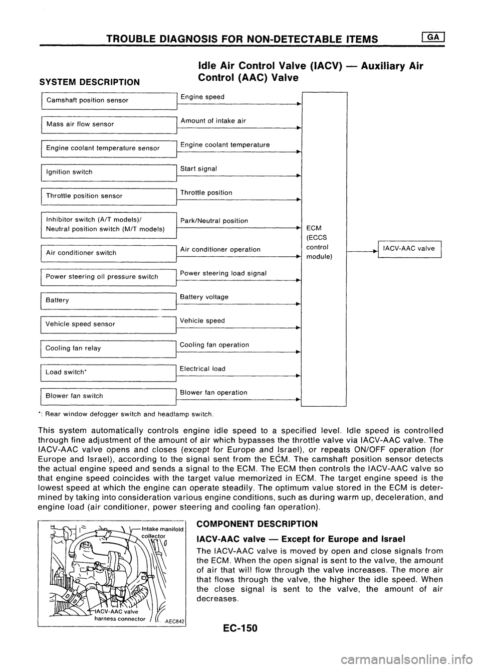
SYSTEM DESCRIPTION Idle
AirControl Valve(IACV) -Auxiliary Air
Control (AAC)Valve
Camshaft positionsensor Engine
speed
I
Mass
airflow sensor Amount
ofintake air
I
Engine coolant temperature sensor Engine
coolant temperature
~
I
Ignition switch Start
signal
I
Throttle positionsensor Throttle
position
~
I
Inhibitor switch(A/Tmodels)/
Park/Neutralposition
Neutral position switch(M/Tmodels) ECM
(ECCS
Air conditioner operation control
!
IACV-AAC valve
I
Air conditioner switch
module)
Power steering oilpressure switch Power
steering loadsignal
I
Battery
~
Battery voltage
Vehicle speedsensor Vehicle
speed
Cooling fanrelay Cooling
fanoperation
Load switch' Electrical
load
Blower fanswitch Blower
fanoperation
': Rear window defogger switchandheadlamp switch.
This system automatically controlsengineidlespeed toaspecified level.Idlespeed iscontrolled
through fineadjustment ofthe amount ofair which bypasses thethrottle valveviaIACV-AAC valve.The
IACV-AAC valveopens andcloses (except forEurope andIsrael), orrepeats ON/OFF operation (for
Europe andIsrael), according tothe signal sentfrom theECM. Thecamshaft positionsensordetects
the actual engine speedandsends asignal tothe ECM. TheECM thencontrols theIACV-AAC valveso
that engine speedcoincides withthetarget valuememorized inECM. Thetarget engine speedisthe
lowest speedatwhich theengine canoperate steadily. Theoptimum valuestored inthe ECM isdeter-
mined bytaking intoconsideration variousengineconditions, suchasduring warmup,deceleration, and
engine load(airconditioner, powersteering andcooling fanoperation).
COMPONENT DESCRIPTION
IACV-AAC valve-Except forEurope andIsrael
The IACV-AAC valveismoved byopen andclose signals from
the ECM. When theopen signal issent tothe valve, theamount
of air that willflow through thevalve increases. Themore air
that flows through thevalve, thehigher theidle speed. When
the close signal issent tothe valve. theamount ofair
decreases.
EC-150
Page 873 of 1701
Repairharness orcon-
nectors. INSPECTION
END
Check thefollowing.
• Harness connectors
QD,@orQD,
@
• 10A fuse
• Harness foropen or
short between IACV-AAC
valve andfuse
If NG, repair harness or
connectors.
NG OK
NG
OK
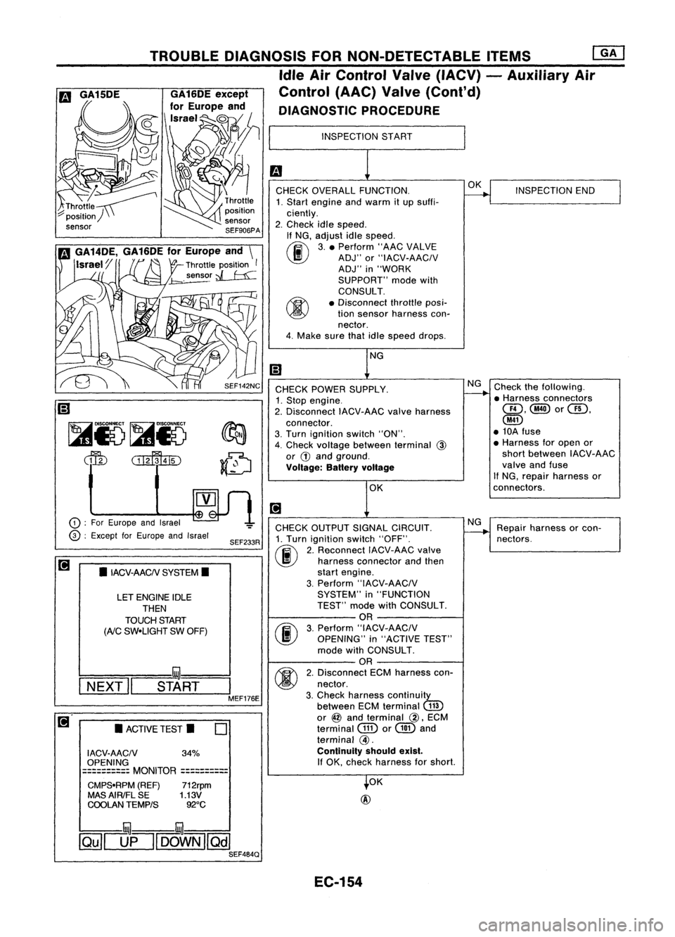
INSPECTION
START
CHECK OVERALL FUNCTION.
1. Start engine andwarm itup suffi-
ciently.
2. Check idlespeed.
If NG, adjust idlespeed.
~ 3.• Perform "AACVALVE
~ ADJ"or"IACV-AACIV
ADJ" in"WORK
SUPPORT" modewith
CONSULT.
• Disconnect throttleposi-
tion sensor harness con-
nector.
4. Make surethatidlespeed drops.
OK
@
CHECK
POWER SUPPLY.
1. Stop engine.
2. Disconnect IACV-AACvalveharness
connector.
3. Turn ignition switch"ON".
4. Check voltage between terminal
@
or
G)
and ground.
Voltage: Batteryvoltage
CHECK OUTPUT SIGNALCIRCUIT.
1. Turn ignition switch"OFF".
(ij\
2.Reconnect IACV-AACvalve
~ harnessconnector andthen
start engine.
3. Perform "IACV-AACIV
SYSTEM" in"FUNCTION
TEST" modewithCONSULT.
OR
(F.I\
3.Perform "IACV-AACIV
~ OPENING" in"ACTIVE TEST"
mode withCONSULT.
OR
M
2.Disconnect ECMharness con-
~ nectar.
3. Check harness continuity
between ECMterminal
(ill)
or
@
and terminal
@,
ECM
terminal
GID
or
@
and
terminal
@.
Continuity shouldexist.
If
OK, check harness forshort.
SEF233R
SEF142NC
o
•
ACTIVE TEST.
LET
ENGINE IDLE
THEN
TOUCH START
(AiC
SW-UGHT SWOFF)
•
IACV-AACN SYSTEM.
I ACV-AACN 34%
OPENING
==========
MONITOR
==========
CMPS-RPM (REF)712rpm
MAS AIRIFL SE 1.13V
COOLAN TEMPtS 92°C
TROUBLE
DIAGNOSIS FORNON-DETECTABLE ITEMS
ffiJ
Idle AirControl Valve(IACV) -Auxiliary Air
Control (AAC)Valve(Cont'd)
DIAGNOSTIC PROCEDURE
!:::=====mul===
I
NEXT" START
I
MEF176E
CD
:
For Europe andIsrael
@ :
Except forEurope andIsrael
~
Ii)
~i5~i5
dfu
CillffuID
illU--illU
~[]fl[OOWN][Qill SEF484Q
EC-154
Page 875 of 1701
TROUBLEDIAGNOSIS FORNON-DETECTABLE ITEMS
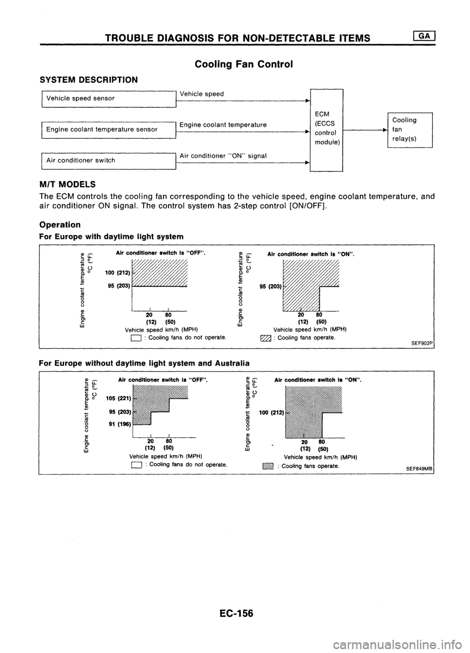
Cooling FanControl
SYSTEM DESCRIPTION
Vehicle speedsensor
Engine coolant temperature sensor
Air conditioner switch Vehicle
speed
Engine coolant temperature
Air conditioner "ON"signal
EGM
(EGGS
control
module) Gooling
fan relay(s)
MIT MODELS
The ECM controls thecooling fancorresponding tothe vehicle speed,engine coolant temperature, and
air conditioner ONsignal. Thecontrol system has2-step control [ON/OFF].
Operation
For Europe withdaytime lightsystem
E~
::J
0
~Z;
2i
o
E
~
~
'0
o
o
Gl
c
'0>
c
w
Air
conditioner switchIs"OFF".
/,
100 (212)
95 (203)
rr
20 80
(12) (50)
Vehicle speedkm/h(MPH)
D :
Cooling fansdonot operate.
~
iL
Airconditioner switchIs"ON".
~ ~ 11'l1/1~~~
:v
() /'/"
0.
0
E
~
!
95(203)
.~ 2080
ill
(12)(50)
Vehicle speedkm/h(MPH)
EZ2l :
Cooling fansoperate.
SEF902P
For Europe withoutdaytime lightsystem andAustralia
Gl_
2~
.,
-
:v ()
0.0
E
~
~
'0
o
o
Gl
c
'0>
c
w
Air
conditioner switchIs"OFF",
105 (221)
95 (203)
91 (196)
2080
(12) (50)
Vehicle speedkm/h(MPH)
D :
Cooling fansdonot operate.
Air
conditioner switchIs"ON",
100 (212)
2080
(12) (50)
Vehicle speedkm/h(MPH)
~ :Cooling fansoperate.
SEF649MB
EC-156