Page 921 of 1701
TROUBLEDIAGNOSIS FORNON-DETECTABLE ITEMS
Valve Timing Control (VTC)(Cant'd)
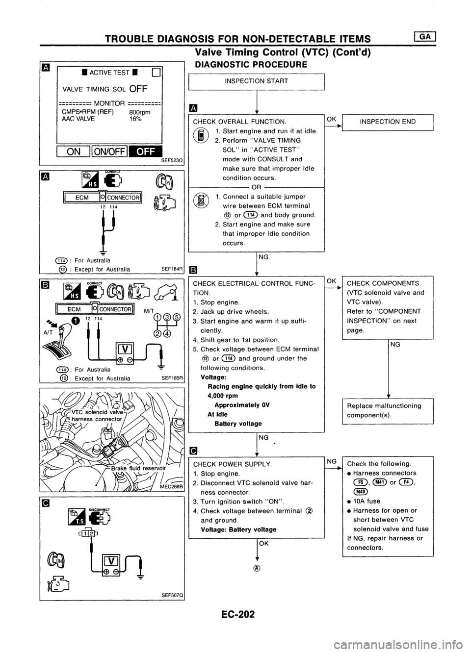
DIAGNOSTIC PROCEDURE
INSPECTION START
m
CHECK OVERALL FUNCTION.
~
INSPECTION
END
00
1.
Start engine andrunitat idle.
2. Perform "VALVETIMING
SOL" in"ACTIVE TEST"
mode withCONSULT and
make surethatimproper idle
condition occurs.
OR
00
1.
Connect asuitable jumper
wire between ECMterminal
@
or
@
andbody ground.
2. Start engine andmake sure
that improper idlecondition
occurs.
NG
iii
CHECK ELECTRICAL CONTROLFUNC-OK
CHECK COMPONENTS
TION.
-+
(VTCsolenoid valveand
1. Stop engine. VTC
valve).
2. Jack updrive wheels. Refer
to"COMPONENT
3. Start engine andwarm itup suffi- INSPECTION"
onnext
ciently. page.
4. Shift gearto1st position.
NG
5. Check voltage between ECMterminal
@
or
@
andground underthe
following conditions.
Voltage: Racing engine quickly fromidleto
4,000 rpm
Approximately OV
Replacemalfunctioning
At idle
component(s).
Battery voltage
NG
.
[!J
CHECK POWER SUPPLY. NG
Check thefollowing.
1. Stop engine.
~
•Harness connectors
2. Disconnect VTCsolenoid valvehar- QD,@or@,
ness connector.
@
3. Turn ignition switch"ON". •
10A fuse
4. Check voltage between terminal
@
•
Harness foropen or
and ground. short
between VTC
Voltage: Batteryvoltage
solenoid
valveandfuse
OK If
NG, repair harness or
connectors.
SEF185R
SEF507Q
SEF184R
M/T
@@
~r5 ~
~£)
II
ECM
~CONNECTORII
12 114
~
ON
II
ON/OFF
IEDI
SEF523Q
•
ACTIVE TEST.
0
VALVE TIMING SOL
OFF
==========
MONITOR
==========
CMPS.RPM (REF)800rpm
AAC VALVE 16%
@):
ForAustralia
@:
Except forAustralia
@):
ForAustralia
12 :Except forAustralia
~i)~ID~
II
ECM
NCONNECTORII
A~fl "'"
~
EC-202
Page 922 of 1701
TROUBLEDIAGNOSIS FORNON-DETECTABLE ITEMS
Valve Timing Control (VTC)(Cont'd)
~i5
~
114 :
For Australia
@: Except forAustralia
II
~i5
ECM E
CONNECTOR
II
12 114
• VALVE TIMING SNCKT.
DOES THESOLENOID
VALVE MAKE
AN OPERATING SOUND
EVERY 3SECONDS?
NEXT
II
NO
II
YES
I
SEF186R
MEF813D
I!]
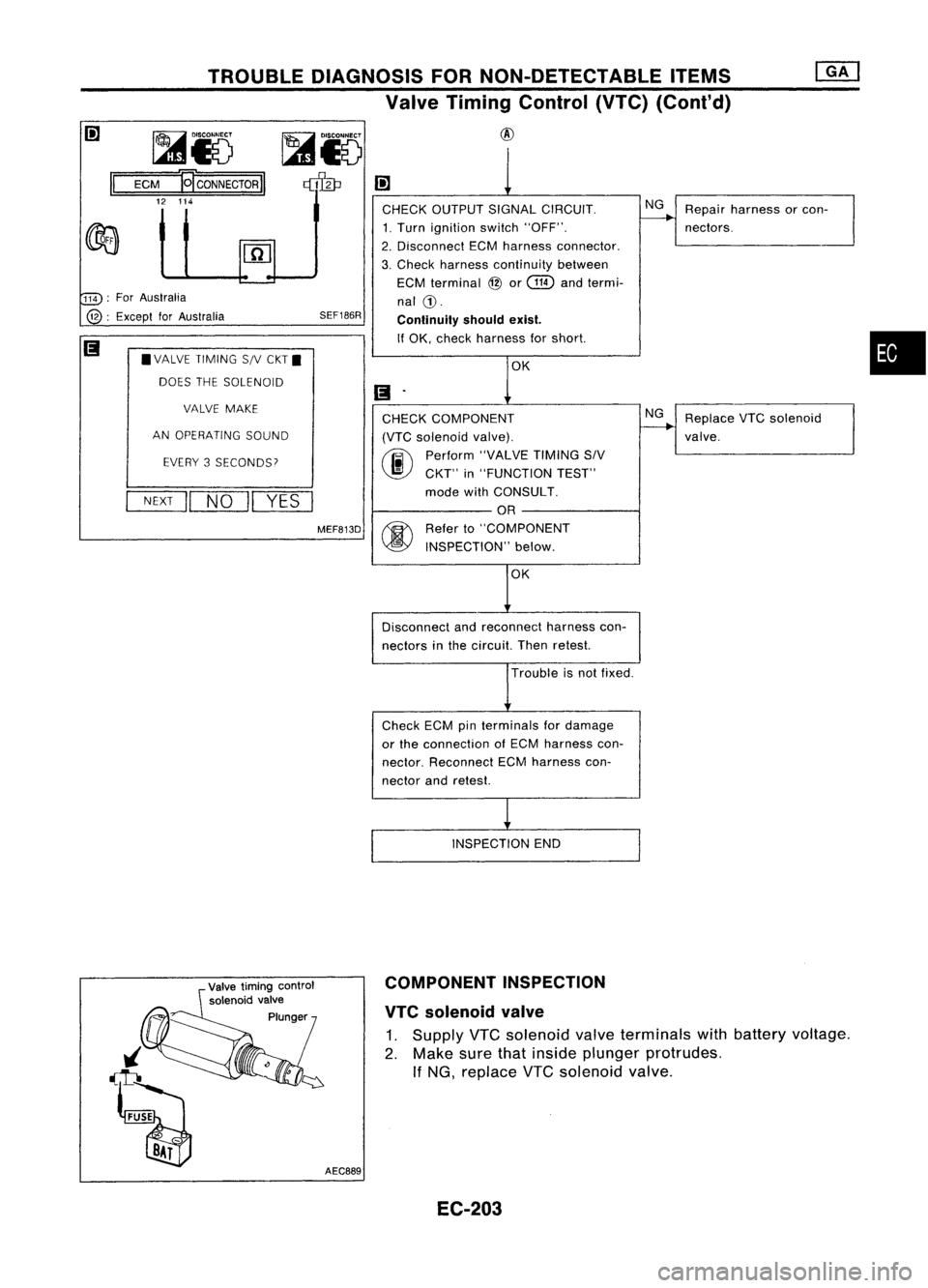
CHECK OUTPUT SIGNALCIRCUIT. NG
Repair harness orcon-
~
1. Turn ignition switch"OFF". nectors.
2. Disconnect ECMharness connector.
3. Check harness continuity between
ECM terminal
@
or
(ill)
andtermi-
nal
CD.
Conlinuity shouldexist.
If OK, check harness forshort.
OK
(I
.
CHECK COMPONENT NG
Replace VTCsolenoid
(VTC solenoid valve).
~
valve.
@)
Perform
"VALVETIMINGSIV
CKT" in"FUNCTION TEST"
mode withCONSULT.
OR
@
Refer
to"COMPONENT
INSPECTION" below.
OK
Disconnect andreconnect harnesscon-
nectors inthe circuit. Thenretest.
Trouble isnot fixed.
Check ECMpinterminals fordamage
or the connection ofECM harness con-
nector. Reconnect ECMharness con-
nector andretest.
INSPECTION END
•
Valve timing control
solenoid valve
Plunger
i
~ ~ AEC889COMPONENT
INSPECTION
VTC solenoid valve
1. Supply VTCsolenoid valveterminals withbattery voltage.
2. Make surethatinside plunger protrudes.
If NG, replace VTCsolenoid valve.
EC-203
Page 934 of 1701
![NISSAN ALMERA N15 1995 Service Manual L,__
R_E_CO_R_D __
I
MEC212B
Ii]
*
MONITOR
*
NO FAIL
0
LOAD SIGNAL OFF
•
r-
(A)
INSPECTION
START
m
CHECK OVERALL FUNCTION-I. NG
Check rearwindow
1) Turn ignition switch"ON",
--- NISSAN ALMERA N15 1995 Service Manual L,__
R_E_CO_R_D __
I
MEC212B
Ii]
*
MONITOR
*
NO FAIL
0
LOAD SIGNAL OFF
•
r-
(A)
INSPECTION
START
m
CHECK OVERALL FUNCTION-I. NG
Check rearwindow
1) Turn ignition switch"ON",
---](/manual-img/5/57349/w960_57349-933.png)
L,__
R_E_CO_R_D __
I
MEC212B
Ii]
*
MONITOR
*
NO FAIL
0
LOAD SIGNAL OFF
•
r-
(A)
INSPECTION
START
m
CHECK OVERALL FUNCTION-I. NG
Check rearwindow
1) Turn ignition switch"ON",
----+
defogger circuit.
00
2)
Check "LOAD SIGNAL" in
(Goto
I
Procedure A
I,)
"DATA MONITOR" modewith
CONSULT. Rear window defogger switch
is "ON": ON
Rear window defogger switch
.
is"OFF": OFF
OR
@
2)
Check voltage between ECM
terminal
@
or
@
and
ground underthefollowing
conditions.
Voltage:
Rear window defogger
switch is"ON".
Battery voltage
Rear window defogger
switch is"OFF".
Approximately OV
OK
Ii]
CHECK OVERALL FUNCTION-II. NG
Check lighting switchcir-
1) Turn rearwindow defogger switch
----+
cuit.
"OFF", (Goto
I
Proceduffil?J)
00
2)
Check "LOAD SIGNAL" in
"DATA MONITOR" modewith
CONSULT.
Lighting switchis"ON": ON
Lighting switchis"OFF": OFF
OR
@
2)
Turn ignition switch"OFF"
3) Check voltage between ECM
terminal
i@J
or
@
and
ground underthefollowing
cond itions.
Voltage: Lighting switchis"ON".
Battery voltage
Lighting switchis"OFF".
Approximately OV
SEF240R
SEF241R
SEF197R
OFF
*
NO FAIL
0
TROUBLE
DIAGNOSIS FORNON-DETECTABLE ITEMS
Electrical LoadSignal (Cont'd)
DIAGNOSTIC PROCEDURE
~15@a0
ECM
ECONNECTORII
33 55
~15~
ECM
E
CONNECTOR
II
45 35
~15~
ECM
€I'
CONNECTOR
II
33 60
*
MONITOR
LOAD SIGNAL
@:
ForAustralia
33 :Except forAustralia
@:
ForAustralia
45 ,
Except forAustralia
@:
ForAustralia
33 :
Except forAustralia
___
RE_C_O_R_D __
I
MEC212B
II
II
II
EC-215
Page 937 of 1701
TROUBLEDIAGNOSIS FORNON-DETECTABLE ITEMS
Electrical LoadSignal (Cont'd)
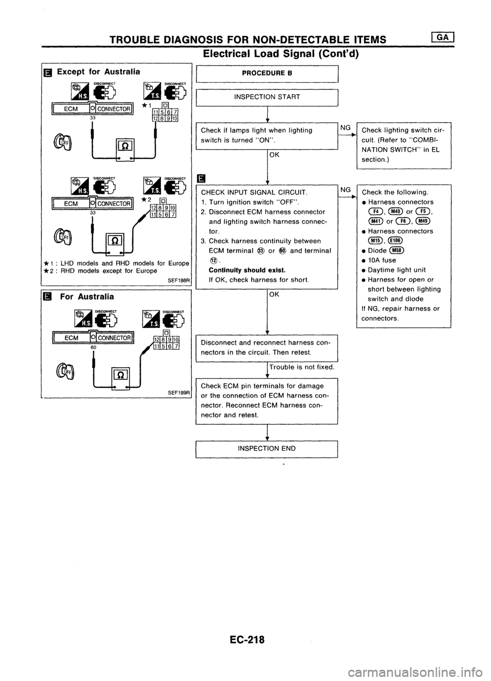
PROCEDURE B
INSPECTION START
Check iflamps lightwhen lighting NG
Check lighting switchcir-
switch isturned "ON".
-----..--..
cui!.(Refer to"COMBI-
OK NATION
SWITCH" inEL
section.)
Ii
CHECK INPUTSIGNAL CIRCUIT. NG
Check thefollowing.
1. Turn ignition switch"OFF".
-----..--..
•Harness connectors
2. Disconnect ECMharness connector CID,@or@,
and lighting switchharness connec- @orQD,@
tor. •
Harness connectors
3. Check harness continuity between
@,@ID
ECM terminal
@
or@ and terminal .Diode@
@. •10A fuse
Continuity shouldexist.
•
Daytime lightunit
If OK, check harness forshort. •
Harness foropen or
OK short
between lighting
switch anddiode
If
NG, repair harness or
connectors.
Disconnect andreconnect harnesscon-
nectors inthe circuit. Thenretest.
Trouble isnot fixed.
Check ECMpinterminals fordamage
or the connection ofECM harness con-
nector. Reconnect ECMharness con-
nector andretest.
INSPECTION END
SEF199R
~&5
~15
1='
=E=CM===IE[ CONNECTOR
II
60
SEF188R
~15
~i5
II
ECM
19"
CONNECTOR
II
33
*
1:LHD models andRHD models forEurope
*
2:RHD models exceptforEurope
II
Except forAustralia
I
~Io ~io----~
II
ECM E!'CONNECTOR
II
33
II
ForAustralia
EC-218
Page 940 of 1701
TROUBLEDIAGNOSIS FORNON-DETECTABLE ITEMS~
Torque Converter ClutchSolenoid Valve(Cont'd)
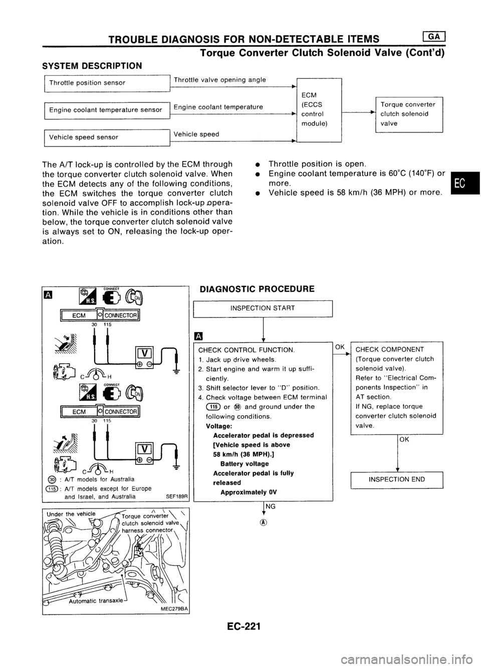
SYSTEM DESCRIPTION
Throttle position sensor Throttle
valveopening angle
Engine coolant temperature sensorEnginecoolant temperature ECM
(ECCS
control
module) Torque
converter
clutch solenoid
valve
Vehicle speedsensor Vehicle
speed
The
AfT
lock-up iscontrolled bythe ECM through
the torque converter clutchsolenoid valve.When
the ECM detects anyofthe following conditions,
the ECM switches thetorque converter clutch
solenoid valveOFFtoaccomplish lock-upDpera-
tion. While thevehicle isin conditions otherthan
below, thetorque converter clutchsolenoid valve
is always settoON, releasing thelock-up oper-
ation.
•
•
•
Throttle
position isopen .
Engine coolant temperature is60°C (140°F) or•
more.
Vehicle speedis58 kmfh (36MPH) ormore .
m ~
i3~
II
ECM
HCONNECTORII
30 115
ID
cf6~H
~i3~
II
ECM E
CONNECTOR
II
30 115
iIJ
ID
cf6~H
@> :
AIT
models forAustralia
@:
AlTmodels exceptforEurope
and Israel, andAustralia
SEF189RDIAGNOSTIC
PROCEDURE
INSPECTION START
CHECK CONTROL FUNCTION.
1. Jack updrive wheels.
2. Start engine andwarm itup suffi-
ciently.
3. Shift selector leverto"D" position.
4. Check voltage between ECMterminal
GID
or
@
and ground underthe
following conditions.
Voltage: Accelerator pedalisdepressed
[Vehicle speedisabove
58 km/h (36MPH).]
Battery voltage
Accelerator pedalisfully
released ApprOXimately OV
OK
CHECK COMPONENT
(Torque converter clutch
solenoid valve).
Refer to"Electrical Com-
ponents Inspection" in
AT section.
If NG, replace torque
converter clutchsolenoid
valve.
OK
INSPECTION END
MEC279BA NG
EC-221
Page 941 of 1701
![NISSAN ALMERA N15 1995 Service Manual TROUBLEDIAGNOSIS FORNON-DETECTABLE ITEMS
@]
Torque Converter ClutchSolenoid Valve(Cont'd)
@
@ :
AIT
models forAustralia
@:
NTmodels exceptforEurope
and Israel, andAustralia
I!J
1
CHECK POW NISSAN ALMERA N15 1995 Service Manual TROUBLEDIAGNOSIS FORNON-DETECTABLE ITEMS
@]
Torque Converter ClutchSolenoid Valve(Cont'd)
@
@ :
AIT
models forAustralia
@:
NTmodels exceptforEurope
and Israel, andAustralia
I!J
1
CHECK POW](/manual-img/5/57349/w960_57349-940.png)
TROUBLEDIAGNOSIS FORNON-DETECTABLE ITEMS
@]
Torque Converter ClutchSolenoid Valve(Cont'd)
@
@ :
AIT
models forAustralia
@:
NTmodels exceptforEurope
and Israel, andAustralia
I!J
1
CHECK POWER SUPPLY. NG
Check thefol/owing.
1. Stop engine.
--.--..
•Harness connectors
2. Disconnect torqueconverter clutch
@),
solenoid valveharness connector. •10A fuse
3. Turn ignition switch"ON".
•Harness foropen or
4. Check voltage between terminal
@
shortbetween torque
and ground. converterclutchsole-
Voltage: Batteryvoltage
noidvalve andfuse
" NG, repair harness or
OK connectors.
[;J
CHECK OUTPUT SIGNALCIRCUIT. NG
Check thefollowing.
1. Turn ignition switch"OFF".
--.--..
•Harness connectors
2. Disconnect ECMharness connector.
aD,@
3. Check harness continuity between •Harness connectors
ECM terminal
(ill)
or
@
and termi-
@,@!)
nal (D. •Harness connectors
Continuity shouldexist.
@),@D
" OK, check harness forshort. •
Harness foropen or
short between ECM
OK andtorque converter
clutch solenoid valve
If
NG, repair harness or
connectors.
CHECK COMPONENT NG
Replace torqueconverter
(Torque converter clutchsolenoid
~
clutchsolenoid valve.
valve).
Refer to"Electrical Components
Inspection" inAT section.
OK
Disconnect andreconnect harnesscon-
nectors inthe circuit. Thenretest.
Trouble isnot fixed.
Check ECMpinterminals fordamage
or the connection ofECM harness con-
nector. Reconnect ECMharness con-
nector andretest.
.
INSPECTION END
SEF190R
SEF513Q
rilio
ECM
HCONNECTORII
115 30
~i5
~
II
EC-222
Page 943 of 1701
TROUBLEDIAGNOSIS FORNON-DETECTABLE ITEMS
MIL &Data LinkConnectors (Cont'd)
RHO
models
EC-MIL-02
I
DATA LINK
CONNECTOR
FOR CONSULT
.~
~ B
ECM (ECCS
CONTROL
MODULE)
em
@:
Models withtachometer
@:
Models without tachometer
*1 ... @30 @40
,
*2 ... @32
@
8
,
-: Detectable 1ine
for DTC
-: Non-detectable
line forDTC
~LiJ
G/R G/W
~ ~
Refer
toEL-POWER.
FUSE
BLOCK
(JIB)
COMBINATION
METER (MALFUNCTION
INDICATOR
LAMP)
~
@
1*.21
ORIL
i
G
1
m
LiJ!4J
G/B
GYIL
I ~ I
t
G/B GY/L
tt
l
'DJOINT
CONNECTOR-5
~~~
ORIL
@
G/B
GYIL
G/RG/W
1~~{F~5----------~~~-~~~---------~qp~-~~1
ORIL
G/B
GYIL
G/RG/W
I II II
ORIL
G/B
GY/L
G/RG/W
~ mum
~wrn
LCHK SCISCI CHECKSCI
R RXTX CL
Refertolast page
(Foldout page).
~~
~OR
HECOS9
EC-224
Page 960 of 1701
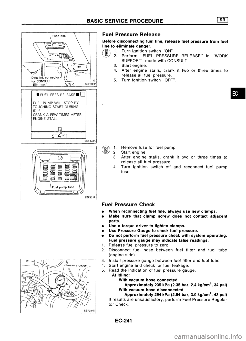
~U5e
box
~~~
~11~1-
Datalinkconnector ~"
for CONSULT
t=====/
• FUEL PRESRELEASE. D
FUEL PUMP WillSTOP BY
TOUCHING STARTDURING
IDLE.
CRANK AFEW TIMES AFTER
ENGINE STALL
---S-T~-RT--
BASIC
SERVICE PROCEDURE
Fuel Pressure Release
Before disconnecting fuelline, release fuelpressure fromfuel
line toeliminate danger.
~ 1.Turn ignition switch"ON".
\J!I}
2.Perform "FUELPRESSURE RELEASE"in"WORK
SUPPORT" modewithCONSULT.
3. Start engine.
4. After engine stalls,crankittwo orthree times to
release allfuel pressure.
5. Turn ignition switch"OFF".
•
@ ~:
3.
SEF823K
SEF921P
SEF034K
Remove
fuseforfuel pump.
Start engine.
After engine stalls,crank
it
two orthree times to
release allfuel pressure.
4. Turn ignition switchoffand reconnect fuelpump
fuse.
Fuel Pressure Check
• When reconnecting fuelline, always usenew clamps.
• Make surethatclamp screwdoesnotcontact adjacent
parts.
• Use atorque drivertotighten clamps.
• Use Pressure Gaugetocheck fuelpressure.
• Donot perform fuelpressure checkwithsystem operating.
Fuel pressure gaugemayindicate falsereadings.
1. Release fuelpressure tozero.
2. Disconnect fuelhose between fuelfilter andfuel tube
(engine side).
3. Install pressure gaugebetween fuelfilter andfuel tube.
4. Start engine andcheck forfuel leakage.
5. Read theindication offuel pressure gauge.
At idling:
With vacuum hoseconnected
Approximately 235kPa (2.35 bar,2.4kg/cm
2,
34psi)
With vacuum hosedisconnected
Approximately 294kPa (2.94 bar,3.0kg/cm
2,
43psi)
If
results areunsatisfactory, performFuelPressure Regula-
tor Check.
EC-241