Page 962 of 1701

BASICSERVICE PROCEDURE
Idle Speedllgnition TiminglldleMixtureRatio
Adjustment
PREPARATION
• Make surethatthefollowing partsarein
good order.
(1) Battery
(2) Ignition system
(3) Engine oiland coolant levels
(4) Fuses
(5) ECM harness connector
(6) Vacuum hoses
(7) Airintake system
(Oil filler cap,oillevel gauge, etc.)
(8) Fuel pressure
(9) Engine compression
(10) Throttle valve
Overall inspection sequence
INSPECTION
•
•
•
•
•
•
On
models equipped withairconditioner,
checks shouldbecarried outwhile theair
conditioner is"OFF".
On models equipped withautomatic
transaxle, whenchecking idlespeed, ignition
timing andmixture ratio,checks shouldbe
carried outwhile shiftlever isin "N" position.
When measuring "CO"percentage, insert
probe morethan40cm (15.7 in)into tailpipe.
Turn offheadlamps, heaterblower, rear
defogger. Keep frontwheels pointed straight ahead.
Make thecheck afterthecooling fanhas
stopped.
•
Perform diagnostic testmode II
(Self-diagnostic results).
OK
Check
&
adjust ignition timing.
Check
&
adjust idlespeed.
Check heated oxygen sensor
function. NG
Repair orreplace.
NG Check heated oxygen sensor
harness. NG
Repair orreplace harness.
OK OK
Check CO%. OKReplace heatedoxygen sensor.
NG
INSPECTION END Check
emission controlparts
and repair orreplace ifneces-
sary.
EC-243
NG
Check heated oxygen sensor
function.
OK
Page 965 of 1701

BASICSERVICE PROCEDURE
mJ
Idle Speed/Ignition Timing/IdleMixtureRatio
Adjustment (Cont'd)
@
SEF909P SEF913J
RECORD
@
M
may bethe
se ofa
blem, butthis
arely thecase
II
1
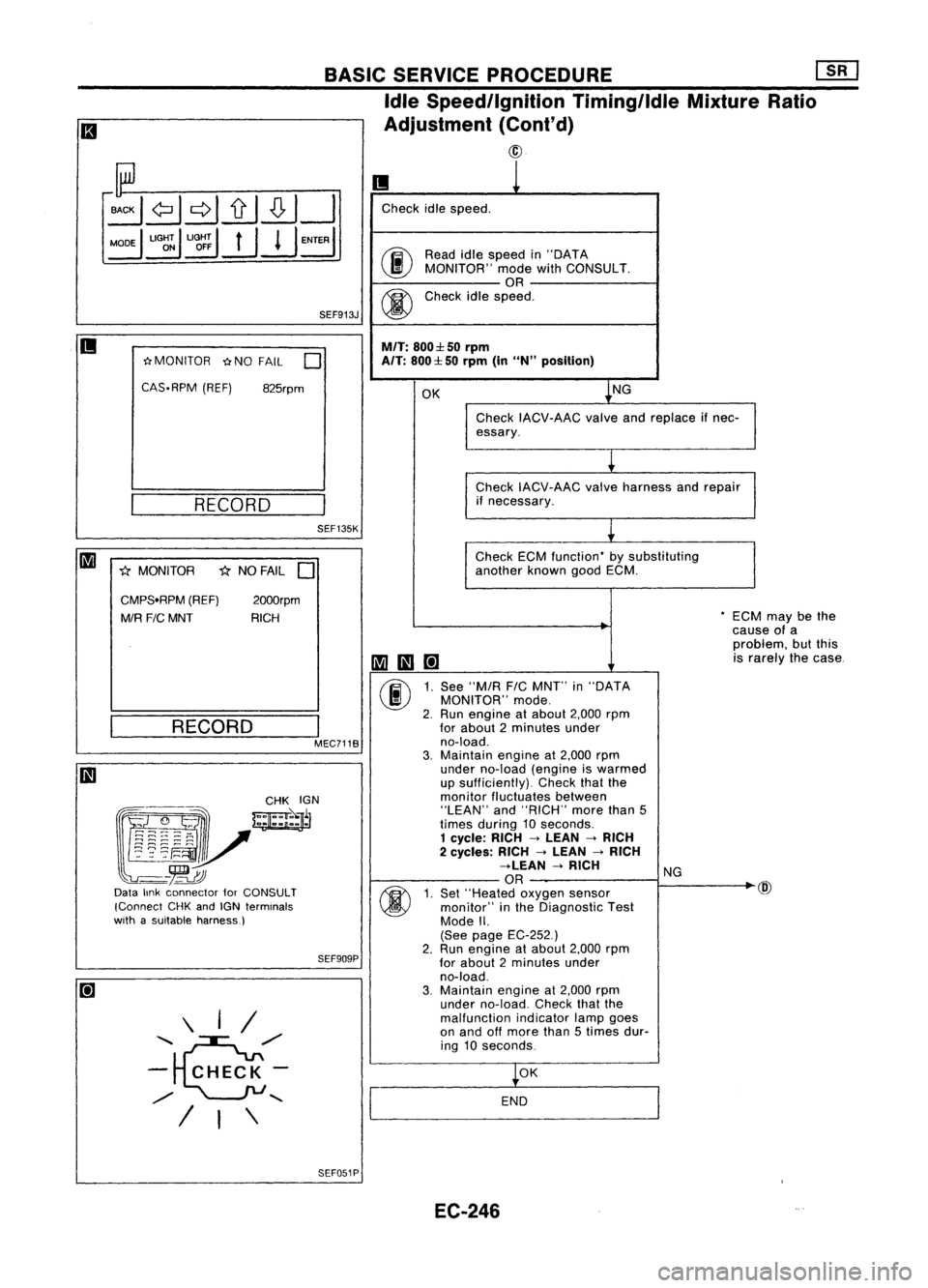
Check idlespeed.
00
Read
idlespeed in"DATA
MONITOR" modewithCONSULT.
OR
@
Check
idlespeed.
M/T:
800:l: 50rpm
A/T:
800:l: 50rpm (in
uN"
position)
OK ~NG
Check IACV-AAC valveandreplace ifnec-
essary.
~
Check IACV-AAC valveharness andrepair
if necessary.
~
Check ECMfunction- bysubstituting
another knowngoodECM.
-EC
cau
pro
1II111[!]
is
r
(j)
1.
See "M/R
FIC
MNT" in"DATA
MONITOR" mode.
2. Run engine atabout 2,000rpm
for about 2minutes under
no-load.
3.
Maintain engineat2,000 rpm
under no-load (engineiswarmed
up sufficiently). Checkthatthe
monitor fluctuates between
"LEAN" and"RICH" morethan5
times during 10seconds.
1 cycle: RICH->LEAN ->RICH
2 cycles: RICH->LEAN ->RICH
->LEAN ->RICH
NG
OR
~
(j)
1.
Set "Heated oxygensensor
monitor" inthe Diagnostic Test
Mode II.
(See page EC-252.)
2. Run
engine atabout 2,000rpm
for about 2minutes under
no-load.
3.
Maintain
engineat2,000 rpm
under no-load. Checkthatthe
malfunction indicatorlampgoes
on and offmore than5times dur-
ing 10seconds.
~OK
END
SEF135K
I
MEC7118
825rpm
2000rpm
RICH
1<
NO FAIL
D
RECORD
\ I/
.........
~/"
- CHECK-
/
......
/ I\
~MONITOR
~NOFAIL
0
CAS-RPM (REF)
CMPS.RPM (REF)
MIR
FIC
MNT
1<
MONITOR
@~~
~~r
~~V
-
-~
Data linkconnector forCONSULT
(Connect CHKandIGN terminals
with asuitable harness)
II
SEF051PEC-246
Page 966 of 1701
![NISSAN ALMERA N15 1995 Service Manual Heatedoxygen sensor
harness connector BASIC
SERVICE PROCEDURE [][]
Idle Speed/Ignition Timing/IdleMixtureRatio
Adjustment (Cont'd)
@
II
MEF031DB
~io
ECM TIcoNNECTORl1
19
LEn
MEC712B
Check
NISSAN ALMERA N15 1995 Service Manual Heatedoxygen sensor
harness connector BASIC
SERVICE PROCEDURE [][]
Idle Speed/Ignition Timing/IdleMixtureRatio
Adjustment (Cont'd)
@
II
MEF031DB
~io
ECM TIcoNNECTORl1
19
LEn
MEC712B
Check](/manual-img/5/57349/w960_57349-965.png)
Heatedoxygen sensor
harness connector BASIC
SERVICE PROCEDURE [][]
Idle Speed/Ignition Timing/IdleMixtureRatio
Adjustment (Cont'd)
@
II
MEF031DB
~io
ECM TIcoNNECTORl1
19
LEn
MEC712B
Check
heated oxygen sensorharness:
1. Turn offengine anddisconnect batteryground
cable.
2. Disconnect ECMharness connector fromECM.
3. Disconnect heatedoxygen sensorharness con-
nector. Thenconnect harness sideterminal for
heated oxygen sensortoground withajumper
wire.
4. Check forcontinuity betweenterminal
@
ofECM
harness connector andbody ground.
Continuity exists OK
Continuity doesnotexist NG
OK
Repairorreplace harness.
Connect ECMharness connector toECM .
•
OR
1.
Connect batteryground cable.
2. Select "ENGCOOLANT TEMP"in
"ACTIVE TEST"mode.
3. Set "COOLANT TEMP"to20"C (68"F) by
touching "Qu"and"Qd" and"UP",
"DWN".
Disconnect enginecoolant temperature
sensor harness connector.
2. Connect aresistor (2.5kQ)between termi-
nals ofengine coolant temperature sensor
harness connector.
3. Connect batteryground cable.
Ii
AEC681
•
ACTIVE TEST.
0
COOLANT TEMP 20°C
===MONITOR=== CMPS.RPM (REF)
Orpm
INJ PULSE
O.7msec
IGN TIMING 5BTDC
DISCONNFCT
Enginecoolant
10 temperature
sensor
harness connector
~ ~
00
2.5
k0 resistor
Start
engine andwarm itup until engine coolant
temperature indicatorpointstomiddle ofgauge.
(Be sure tostart engine aftersetting "COOLANT
'-- A_E_C6_8-l2
TEMP"orinstalling a2.5 kQresistor.)
Ii
SEF455QEC-247
Page 967 of 1701

m
1
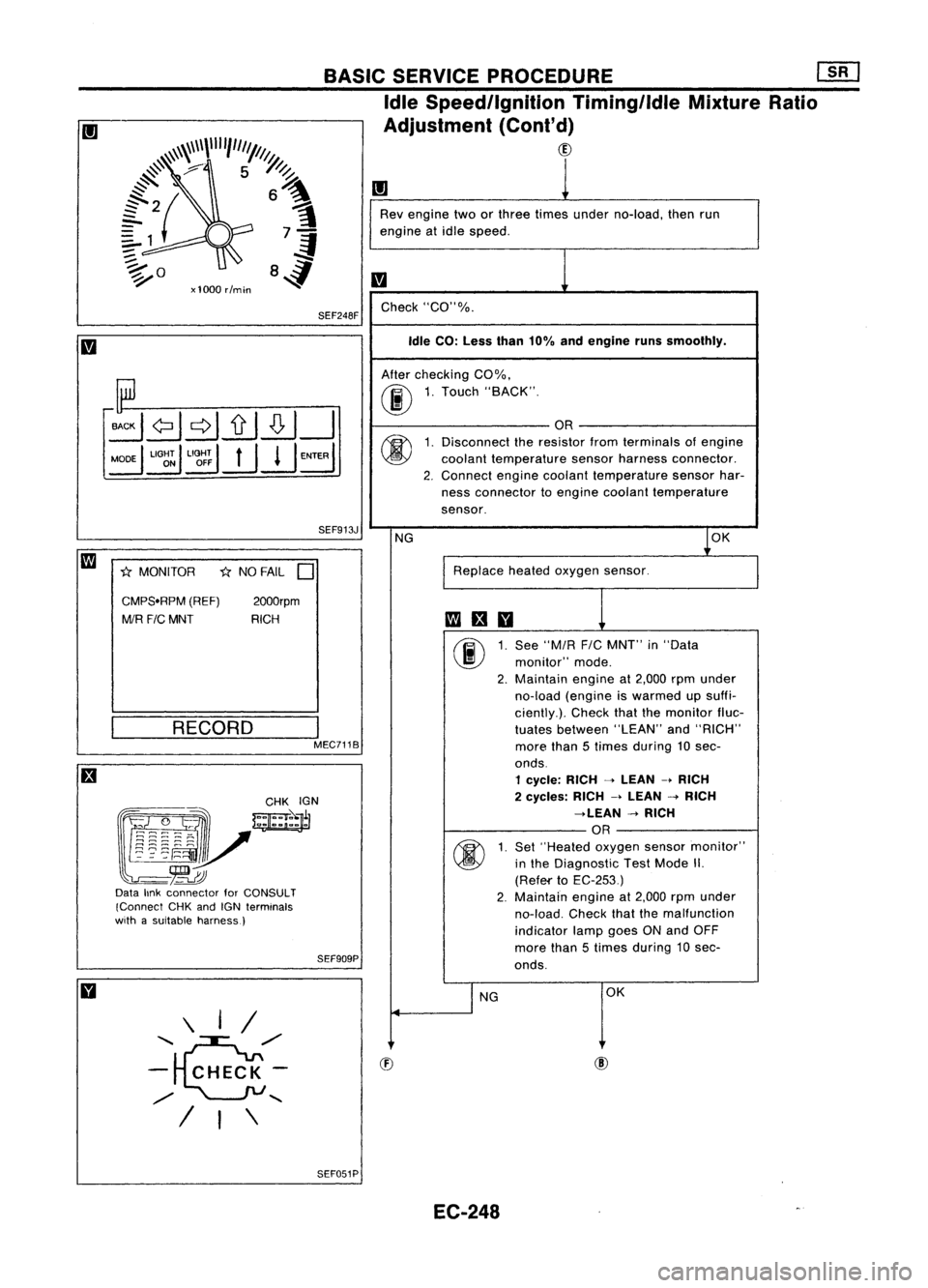
Rev engine twoorthree times under no-load, thenrun
engine atidle speed.
m
Check "CO"%.
Idle CO: Less than10%andengine runssmoothly.
After checking CO%.
00
1.
Touch "BACK".
OR
(j)
1.
Disconnect theresistor fromterminals ofengine
coolant temperature sensorharness connector.
2. Connect
enginecoolant temperature sensorhar-
ness connector toengine coolant temperature
sensor.
NG
1
0K
Replace heatedoxygen sensor.
fa
an
00
1.
See
"MIR
FIC
MNT" in"Data
monitor" mode.
2. Maintain
engineat2,000 rpmunder
no-load (engine iswarmed upsuffi-
ciently.). Checkthatthemonitor fluc-
tuates between "LEAN"and"RICH"
more than5times during 10sec-
onds.
1 cycle: RICH-->LEAN -.RICH
2 cycles: RICH-->LEAN -->RICH
-->LEAN -->RICH
OR
(j)
1.
Set
"Heated oxygensensormonitor"
in the Diagnostic TestMode II.
(Refef'to EC-253)
2. Maintain
engineat2,000 rpmunder
no-load. Checkthatthemalfunction
indicator lampgoesONand OFF
more than5times during 10sec-
onds.
I
NG OK
SEF913J
I
MEC7118
2000rpm
RICH
*
NO FAIL
D
RECORD
SEF909PBASIC
SERVICE PROCEDURE
mJ
Idle Speed/Ignition Timing/ldleMixtureRatio
Adjustment (Cont'd)
CID
SEF248F
\ I/
.........
~/'
- CHECK-
/
.......
/ I\
CMPS.RPM
(REF)
MIR F/CMNT
*
MONITOR
~~~~:?_-~ .
w=jr
~~~~"v
-~
Data linkconnector forCONSULT
(Connect CHKandIGN terminals
with asuitable harness)
SEF051PEC-248
Page 970 of 1701

ON-BOARDDIAGNOSTIC SYSTEMDESCRIPTION
Malfunction IndicatorLamp(MIL)(Cont'd)
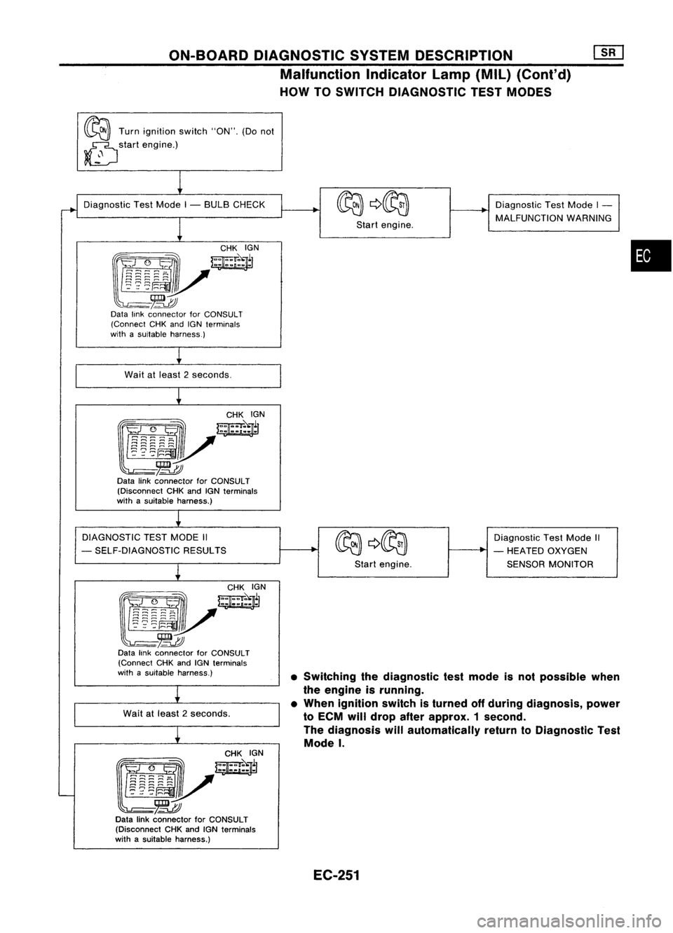
HOW TOSWITCH DIAGNOSTIC TESTMODES
~ Turnignition switch"ON".(Donot
~ startengine.)
~
•SWitching thediagnostic testmode isnot possible when
the engine isrunning.
• When ignition switchisturned offduring diagnosis, power
to ECM willdrop afterapprox. 1second.
The diagnosis willautomatically returntoDiagnostic Test
Mode
I.
Diagnostic
TestMode I- BULB CHECK
1
~yW~r
~-~
Data linkconnector forCONSULT
(Connect CHKandIGNterminals
with asuitable harness.)
Wait atleast 2seconds.
CHKIGN
~J/~l
~-~
Data linkconnector forCONSULT
(Disconnect CHKandIGNterminals
with asuitable harness.)
DIAGNOSTIC TESTMODE II
- SELF-DIAGNOSTIC RESULTS
~
f!i~:~~-~
w;ir
l~mv
-~
Data linkconnector forCONSULT
(Connect CHKandIGN terminals
with asuitable harness.)
Wait atleast 2seconds.
~
~/~~N
~-~
Data linkconnector forCONSULT
(Disconnect CHKandIGNterminals
with asuitable harness.)
I
Startengine.
Start engine. Diagnostic
TestMode I-
MALFUNCTION WARNING
Diagnostic TestMode II
- HEATED OXYGEN
SENSOR MONITOR
•
EC-251
Page 971 of 1701

ON-BOARDDIAGNOSTIC SYSTEMDESCRIPTION ~
Malfunction IndicatorLamp(MIL)(Cont'd)
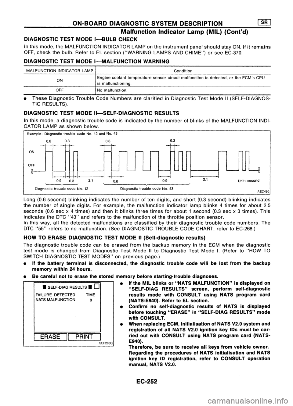
DIAGNOSTIC TESTMODE I-BULB CHECK
In this mode, theMALFUNCTION INDICATORLAMPonthe instrument panelshould stayON.If
it
remains
OFF, check thebulb. Refer toEL section ("WARNING LAMPSANDCHIME") orsee EC-370.
DIAGNOSTIC TESTMODE I-MALFUNCTION WARNING
MALFUNCTION INDICATORLAMP
ON
OFF Condition
Engine coolant temperature sensorcircuitmalfunction isdetected, orthe ECM's CPU
is malfunctioning.
No malfunction.
• These Diagnostic TroubleCodeNumbers areclarified inDiagnostic TestMode II(SELF-DIAGNOS-
TIC RESULTS).
DIAGNOSTIC TESTMODE II-SELF-DIAGNOSTIC RESULTS
In this mode, adiagnostic troublecodeisindicated bythe number ofblinks ofthe MALFUNCTION INDI-
CATOR LAMPasshown below.
Example: Diagnostic troublecodeNo.12and No.43
0.6 0.3
ON
1111
OFF ~
0.9 0.3
0.6
--I~
2.1 0.6
0.9
0.3
Unit:second
Diagnostic troublecodeNo.12 Diagnostic
troublecodeNo.43
AEC490
• SELF-DIAG RESULTS.
0
FAILURE DETECTED TIME
NATS MALFUNCTION
0
I
ERASE
II
PRINT
I
SEF288Q
Long
(0.6second) blinkingindicates thenumber often digits, andshort (0.3second) blinkingindicates
the number ofsingle digits.Forexample, themalfunction indicatorlampblinks 4times forabout 2.5
seconds (0.6secx4times) andthen itblinks threetimes forabout 1second (0.3sec x3 times). This
indicates theDTC "43" andrefers tothe malfunction ofthe throttle position sensor.
In this way, allthe detected malfunctions areclassified bytheir diagnostic troublecodenumbers. The
DTC "55" refers tono malfunction. (SeeDIAGNOSTIC TROUBLECODECHART, refertoEC-268.)
HOW TOERASE DIAGNOSTIC TESTMODE II(Self-diagnostic results)
The diagnostic troublecodecanbeerased fromthebackup memory inthe ECM when thediagnostic
test mode ischanged fromDiagnostic TestMode IIto Diagnostic TestMode
I.
(Refer to"HOW TO
SWITCH DIAGNOSTIC TESTMODES" onprevious page.)
• Ifthe battery terminal isdisconnected, thediagnostic troublecodewillbelost from thebackup
memory within24hours.
• Becareful nottoerase thestored memory beforestarting- troublediagnoses.
• Ifthe MIL blinks or"NATS MALFUNCTION" isdisplayed on
"SELF-OIAG RESULTS"screen,perform self-diagnostic
results modewithCONSULT usingNATS program card
(NA TS-E940). RefertoEL section.
• Confirm noself-diagnostic resultsofNATS isdisplayed
before touching "ERASE" in"SELF-DiAG RESULTS"mode
with CONSULT.
• When replacing ECM,inltialisation ofNATS V2.0system and
registration ofall NATS V2.0 Ignition keyIDsmust becar-
ried outwith CONSULT usingNATS program card(NATS-
E940).
Therefore, besure toreceive allkeys from vehicle owner.
Regarding theprocedures ofNATS initialisation andNATS
ignition key
10
registration, refertoCONSULT operation
manual, NATS V2.0.
EC-252
Page 972 of 1701
ON-BOARDDIAGNOSTIC SYSTEMDESCRIPTION
[]K]
Malfunction Indicatorlamp(Mil)(Cont'd)
DIAGNOSTIC TESTMODE II-HEATED OXYGENSENSORMONITOR
In this mode, theMALFUNCTION INDICATORLAMPdisplays thecondition ofthe fuel mixture (leanor
rich) which ismonitored bythe heated oxygen sensor.
MALFUNCTION INDICATORLAMPFuelmixture condition inthe exhaust gasAirfuel ratio feedback controlcondition
ON Lean
Closedloopsystem
OFF Rich
Remains ONorOFF Anycondition
Openloopsystem
To check theheated oxygen sensorfunction, startengine inDiagnostic TestMode II.Then warm itup
until engine coolant temperature indicatorpointstomiddle ofgauge.
Next runengine atabout 2,000rpmforabout 2minutes underno-load conditions. Makesurethatthe•
MALFUNCTION INDICATORLAMPcomes ONmore than5times within 10seconds withengine running
at 2,000 rpmunder no-load.
EC-253
Page 973 of 1701
ON-BOARDDIAGNOSTIC SYSTEMDESCRIPTION
for CONSULT
t======/
NISSANCONSULT EE940
+
I
~
I
START
I
SUB
MODE
I
SEF253Q CONSULT
CONSULT INSPECTION PROCEDURE
1. Turn offignition switch.
2. Connect "CONSULT" toData linkconnector forCONSULT.
(Data linkconnector forCONSULT islocated behindthefuse
box cover.)
3. Turn onignition switch.
4. Touch "START".
+:
Program card
AE930: ForAustralia
5. Touch "ENGINE",
~ SELECT~S=Y=S=TE=M====
ENGINE
SEF895K
~ SELECT DIAGMODE
[i]
WORK SUPPORT
SELF-DIAG RESULTS
DATA MONITOR
ACTIVE TEST
ECM PART NUMBER
FUNCTION TEST
SEF136P
6.
Perform eachdiagnostic testmode according toeach ser-
vice procedure.
For further information, seetheCONSULT Operation Manual.
EC-254