Page 1025 of 1701
TROUBLEDIAGNOSIS FORDTC34
Knock Sensor (KS)
The knock sensor isattached tothe cylinder block.Itsenses
engine knocking usingapiezoelectric element.Aknocking
vibr
ion
fromthecylinder blockissensed asvibrational pres-
sure. Thispressure is
converted
intoa
voltage
signalandsent
to the ECM.
PIEZO-ELEMENT SEF598K
Diagnostic
Trouble Code Malfunctionisdetected when....
No.
34 •An excessively loworhigh voltage fromtheknock
sensor issent toECM. Check
Items
(Possible Cause)
• Harness orconnectors
(The knock sensor circuitisopen orshorted.)
• Knock sensor
DIAGNOSTIC TROUBLECODECONFIRMATION
PROCEDURE
fiii\
1)Turn ignition switch"ON"andselect "DATA
\J!}
MONITOR" modewithCONSULT.
2) Start engine andrunitfor atleast 5seconds atidle
speed.
----------OR -----------
1) Start engine andrunitfor atleast 5seconds atidle
speed.
2) Turn ignition switch"OFF", waitatleast 7seconds
and then turn"ON".
3) Perform "Diagnostic TestMode II"(Self-diagnostic
results) withECM.
EC-306
Page 1029 of 1701
TROUBLEDIAGNOSIS FORDTC43
Throttle Position Sensor(Cont'd)
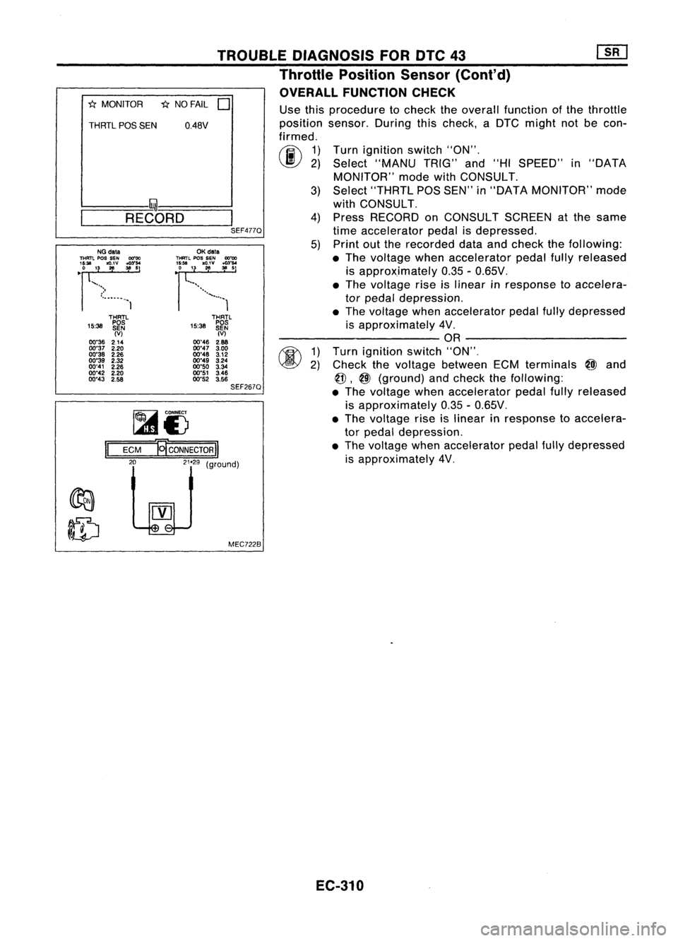
OVERALL FUNCTION CHECK
"*
MONITOR *NO FAIL
0
THRTL
pas
SEN 0.48V
I- I~-----..l
~-R-E-CO-R-D-~I
SEF477QUse
thisprocedure tocheck theoverall function ofthe throttle
position sensor.Duringthischeck, aDTC might notbecon-
firmed.
rij\
1)
~ 2)
Turn
ignition switch"ON".
Select "MANU TRIG"and"HISPEED" in"DATA
MONITOR" modewithCONSULT.
3) Select "THRTL POSSEN" in"DATA MONITOR" mode
with CONSULT.
4) Press RECORD onCONSULT SCREENatthe same
time accelerator pedalisdepressed.
5) Print outthe recorded dataandcheck thefollowing:
• The voltage whenaccelerator pedalfullyreleased
is approximately 0.35-0.65V .
• The voltage riseislinear inresponse toaccelera-
tor pedal depression .
• The voltage whenaccelerator pedalfullydepressed
is approximately 4V.
---------- OR----------
1) Turn ignition switch"ON",
2) Check thevoltage between ECMterminals
@J
and
@,
@
(ground) andcheck thefollOWing:
• The voltage whenaccelerator pedalfullyreleased
is approximately 0.35-0.65V.
• The voltage riseislinear inresponse toaccelera-
tor pedal depression.
• The voltage whenaccelerator pedalfullydepressed
is approximately 4V,
THRTL
15:38 ~~~
(V)
00"46 2.88
00"47 3.00
00"48 3.12
00"49 3.24
00"50 3.34
00"51 3.46
00"52 3.56
SEF267Q
OK
data
THRTL
pos
SEN
OO~
~~~'3. 1
'g;v :":'
................. 1
MEC7228
~i)
ECM
El'coNNEcTORII
LelJ
(9"oodl
II
THRTl
15:38 ~~~
(V)
00"36 214
00"37 2.20
00"38 2.26
00"39 2.32
00"41 2.26
00"42 2.20
00"43 2.58
NG
data
THFm.
pos
SEN 00"00
'~U. '3
~v ~:'
•
")
•...•..•..• 1
EC-310
Page 1034 of 1701
•
DIAGNOSTIC
PROCEDURE
INSPECTION START
Vehicle
speed
sensor
TROUBLE
DIAGNOSIS FORNON-DETECTABLE ITEMS
Vehicle SpeedSensor (VSS)(Conl'd)
COMPONENT DESCRIPTION
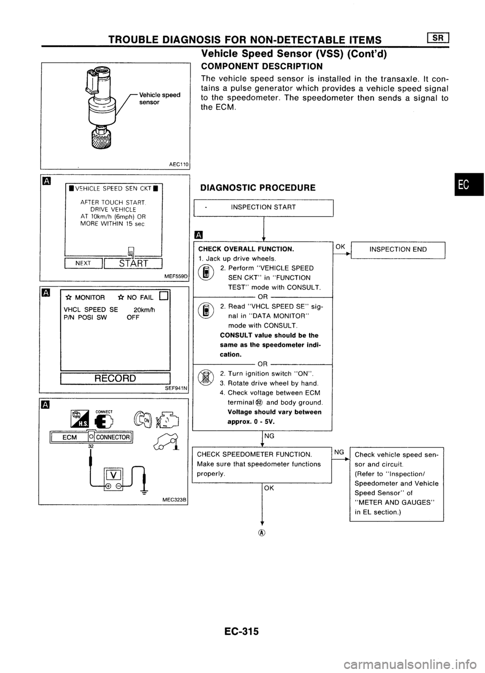
The vehicle speedsensor isinstalled inthe transaxle. Itcon-
tains apulse generator whichprovides avehicle speedsignal
to the speedometer. Thespeedometer thensends asignal to
the ECM.
AEC110
• V~HICLE SPEEDSENCKT.
AFTER TOUCH START.
DRIVE VEHICLE
AT lOkm!h (6mph)OR
MORE WITHIN 15
see
L--- __ '~----'
-N-EX-T
-1I=~_s-T_A~R=T==
MEF559D
*
MONITOR
*
NO FAIL
0
VHCL SPEED SE20kmlh
PIN POSI SW OFF CHECK
OVERALL FUNCTION.
1. Jack updrive wheels.
fi\
2.Perform "VEHICLE SPEED
~ SENCKT" in"FUNCTION
TEST" modewithCONSULT.
OR
rif\
2.Read "VHCl SPEED SE"sig-
~ nalin"DATA MONITOR"
mode withCONSULT.
CONSULT valueshould bethe
same asthe speedometer indi-
cation.
OK
INSPECTION END
RECORD SEF941N
~ CONNECT
f?Ft::J:.~
~£) ~~
1='
=E=CM=-g
CONNECTOR
II~
32
~l
MEC3238
OR
2. Turn ignition switch"ON".
3. Rotate drivewheel byhand.
4. Check voltage between ECM
terminal
@
and body ground.
Voltage shouldvarybetween
approx. 0-5V.
NG
CHECK SPEEDOMETER FUNCTION.
Make surethatspeedometer functions
properly.
OK NG
Check vehicle speedsen-
sor and circuit.
(Refer to"Inspection!
Speedometer andVehicle
Speed Sensor" of
"METER ANDGAUGES"
in El section.)
@
EC-315
Page 1037 of 1701
TROUBLEDIAGNOSIS FORNON-DETECTABLE ITEMS
Start Signal (Cont'd)
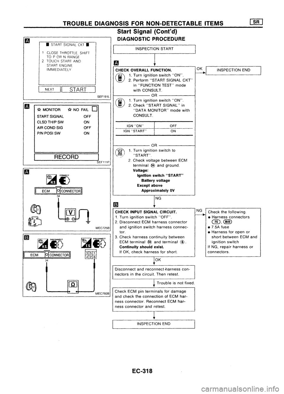
DIAGNOSTIC PROCEDURE
• START SIGNAL CKT•
INSPECTIONSTART
fa CHECK OVERALL FUNCTION.
(ij\
1,Turn ignition switch"ON",
~ 2,Perform "STARTSIGNALCKT"
in "FUNCTION TEST"mode
with CONSULT,
OR
rif\
1,Turn ignition switch"ON",
~ 2,Check "START SIGNAL" in
"DATA MONITOR" modewith
CONSULT,
1
CLOSE THROTILE, SHIFT
TO POR NRANGE
2 TOUCH STARTAND
START ENGINE
IMMEDIATELY
NEXT
II
START
fa
-(:(MONITOR -(:(NO FAIL
0
START SIGNAL OFF
CLSDTH/PSW ON
AfRCONDSIG OFF
PIN POSI SW ON
SEF191L
IGN"ON"
IGN "START"
OFF
ON OK
INSPECTION END
___ RE_C_O_R_D __
I
SEF111P
Checkthefollowing,
• Harness connectors
@,@
• 7,5A fuse
• Harness foropen or
short between ECMand
ignition switch
If NG, repair harness or
connectors,
NG
CHECK INPUTSIGNAL CIRCUIT.
1, Turn ignition switch"OFF",
2, Disconnect ECMharness connector
and ignition switchharness connec-
tor,
3, Check harness continuity between
ECM terminal
@
and terminal
@,
Continuity shouldexist.
If OK, check harness forshort
OK
OR
1, Turn ignition switchto
"START",
2 Check voltage between ECM
terminal
@
and ground,
Voltage: Ignition switch"START"
Battery voltage
Exceplabove
Approximately OV
MEC725B
~15
~
t:1tlliJ
~i3
ECM
E[CONNECTORII
34
~
II
ECM ~CONNECTORI
34
Disconnectandreconnect-harness con-
nectors inthe circuit Thenretest
Trouble isnot fixed,
MEC760B
Check
ECMpinterminals fordamage
and check theconnection ofECM har-
ness connector, ReconnectECMhar-
ness connector andretest
INSPECTION END
EC-318
Page 1040 of 1701
•
INSPECTION
START
m
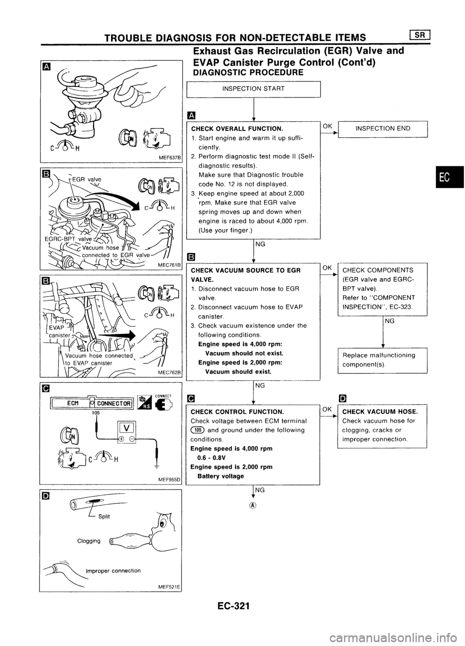
CHECK OVERALL FUNCTION.
~INSPECTION
END
1. Start engine andwarm itup suffi-
ciently.
2. Perform diagnostic testmode II(Self-
diagnostic results).
Make surethatDiagnostic trouble
code No.12isnot displayed.
3. Keep
engine speedatabout 2,000
rpm. Make surethatEGR valve
spring moves upand down when
engine israced toabout 4,000rpm.
(Use yourfinger.)
NG
m
CHECK VACUUM SOURCETOEGR OK
CHECK COMPONENTS
----..
VALVE. (EGR
valve andEGRC-
1. Disconnect vacuumhosetoEGR BPT
valve).
valve. Refer
to"COMPONENT
2. Disconnect
vacuumhosetoEVAP INSPECTION",
EC-323
canister.
3. Check vacuum existence underthe NG
following conditions.
Engine speedis4,000 rpm:
Vacuum shouldnotexist.
Replacemalfunctioning
Engine speedis2,000 rpm:
component(s).
Vacuum shouldexist.
NG
[!J
(!]
CHECK CONTROL FUNCTION. OK
CHECK VACUUM HOSE.
-----.-
Check voltage between ECMterminal Check
vacuum hosefor
@
andground underthefollowing clogging,
cracksor
conditions. improper
connection.
Engine speedis4,000 rpm
0.6 -O.BV
Engine speedis2,000 rpm
Battery voltage
~NG
+
-
MEF637B
MEF955D
TROUBLE
DIAGNOSIS FORNON-DETECTABLE ITEMS
[1[J
Exhaust GasRecirculation (EGR)Valveand
EVAP Canister PurgeControl (Cont'd)
DIAGNOSTIC PROCEDURE
~)5
~~II
EGRC-BPT valve
~~uu~ hose
connected toEGR valve~
(
~
'
MEC761B
Clogging
[!J
r----, ~
CONNECT
II
ECM ~CONNECTORIIl.imJ
£)
105
::::.S.-
~P"P"
'00","'00
MEF521E
EC-321
Page 1041 of 1701
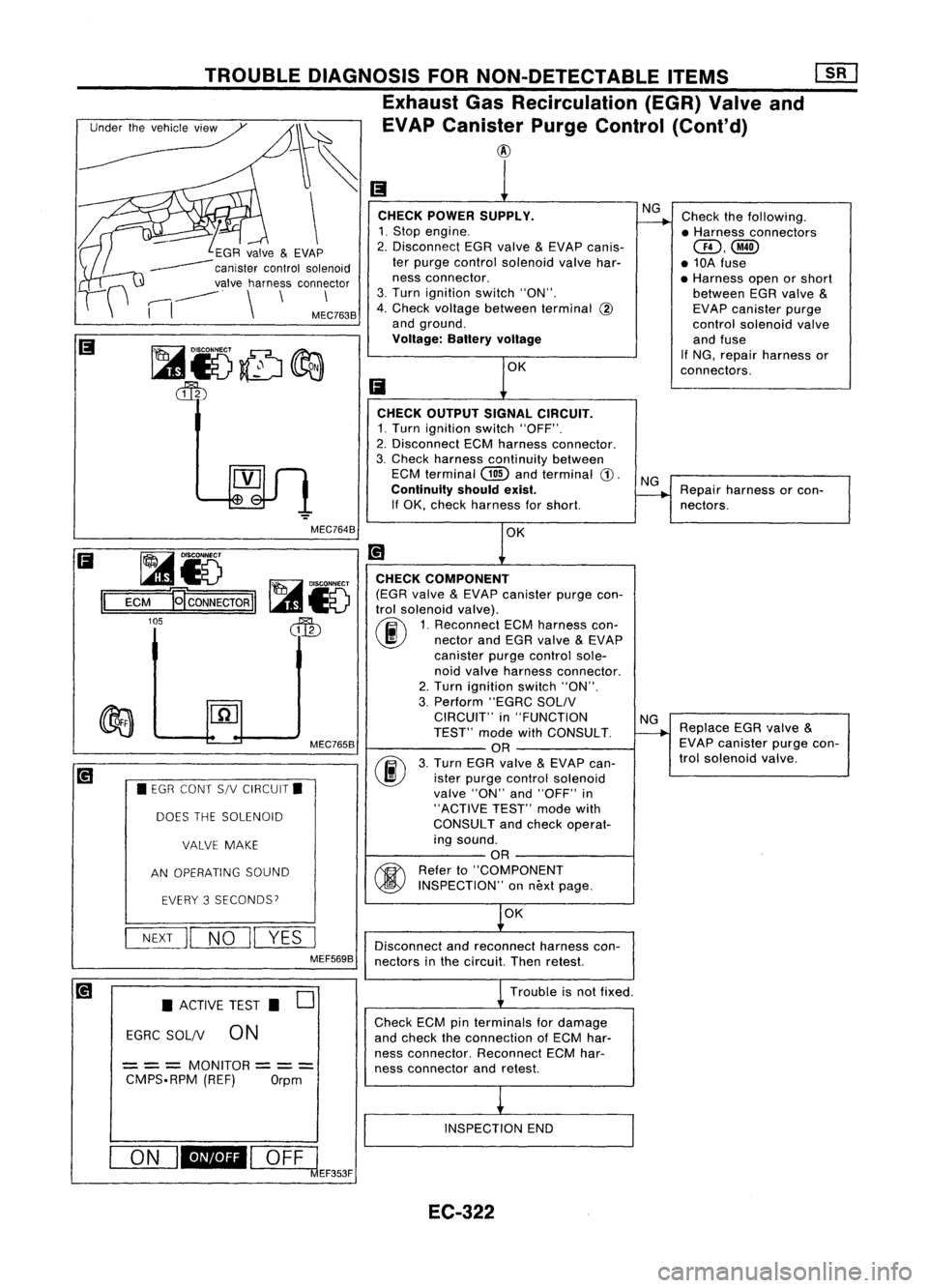
Checkthefollowing.
• Harness connectors
QD,@
• 10A fuse
• Harness openorshort
between EGRvalve
&
EVAP canister purge
control solenoid valve
and fuse
If NG, repair harness or
connectors.
NG
CHECK POWER SUPPLY.
1. Stop engine.
2. Disconnect EGRvalve
&
EVAP canis-
ter purge control solenoid valvehar-
ness connector.
3. Turn ignition switch"ON".
4. Check voltage between terminal
@
and ground.
Voltage: Batteryvoltage
TROUBLE
DIAGNOSIS FORNON-DETECTABLE ITEMS
Exhaust GasRecirculation (EGR)Valveand
_~ ~EVAPcanis:r PurgeControl (Cont'd)
\
~GR valve
&
EVAP
------ canistercontrolsolenoid
valve harness connector
,----,
-----
.
\
\
\
I
I
MEC7638
CHECKOUTPUT SIGNALCIRCUIT.
1. Turn ignition switch"OFF".
2. Disconnect ECMharness connector.
3. Check harness continuity between
ECM terminal
(ill)
andterminal
CD.
Continuity shouldexist.
If OK, check harness forshort.
NG
Repair harness orcon-
nectors.
MEC7648 OK
~i5
1=1
=E=CM=-g CONNECTOR
II
105
MEC7658
• EGR CONT S/VCIRCUIT.
DOES THESOLENOID
VALVE MAKE
AN OPERATING SOUND
EVERY 3SECONDS?
NEXT
II
NO
II
YES
I
MEF5698 CHECK
COMPONENT
(EGR valve
&
EVAP canister purgecon-
trol solenoid valve).
(ij\
1.Reconnect ECMharness con-
~ nectorandEGR valve
&
EVAP
canister purgecontrol sole-
noid valve harness connector.
2. Turn ignition switch"ON".
3. Perform "EGRCSOLIV
CIRCUIT" in"FUNCTION
TEST" modewithCONSULT.
OR
(F./)
3.Turn EGRvalve
&
EVAP can-
~ isterpurge control solenoid
valve "ON"and"OFF" in
"ACTIVE TEST"modewith
CONSULT andcheck operat-
ing sound.
OR
~ Referto"COMPONENT
~ INSPECTION" onnext page.
OK
Disconnect andreconnect harnesscon-
nectors inthe circuit. Thenretest.
NG
Replace EGRvalve
&
EVAP canister purgecon-
trol solenoid valve.
• ACTIVE TEST.
0
EGRC SOL/V
0N
== =
MONITOR
== =
CMPS.RPM (REF)Orpm Trouble
isnot fixed .
Check ECMpinterminals fordamage
and check theconnection ofECM har-
ness connector. ReconnectECMhar-
ness connector andretest.
INSPECTION END
ON
I_I
OFFl
clEF353F
EC-322
Page 1044 of 1701
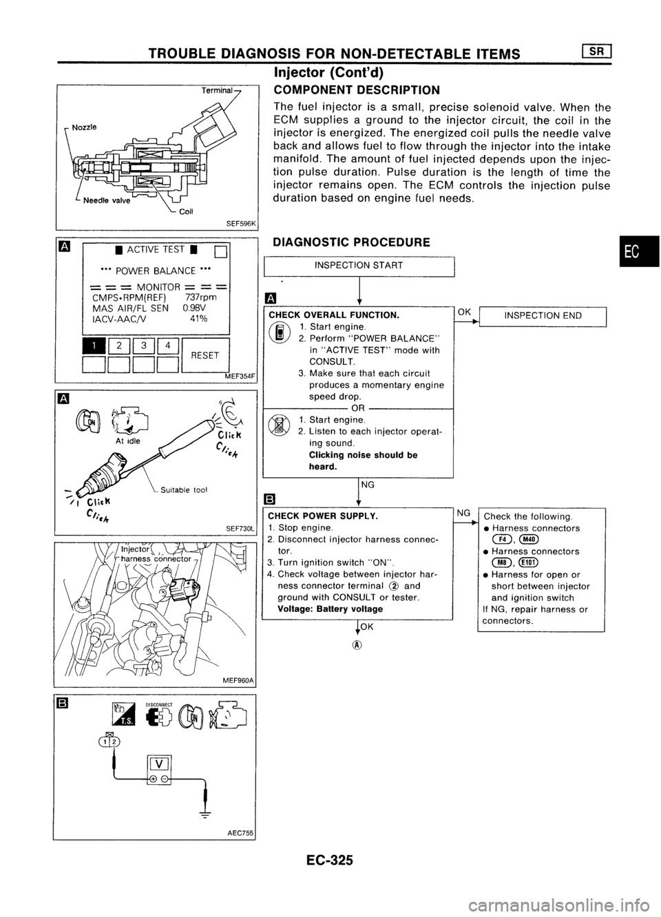
•
INSPECTION END
Check thefollowing.
• Harness connectors
@,@
• Harness connectors
@,
• Harness foropen or
short between injector
and ignition switch
If NG, repair harness or
connectors.
OK
NG
OK
@
INSPECTION
START
DIAGNOSTIC
PROCEDURE
CHECK OVERALL FUNCTION.
(ij\
1.Start engine.
~ 2.Perform "POWER BALANCE"
in "ACTIVE TEST"modewith
CONSULT.
3. Make surethateach circuit
produces amomentary engine
speed drop.
OR
~ 1.Start engine.
~ 2.Listen toeach injector operat-
ing sound.
Clicking noiseshould be
heard.
CHECK POWER SUPPLY.
SEF730L
1.Stop engine.
2. Disconnect injectorharness connec-
tor.
3. Turn ignition switch"ON".
4. Check voltage between injectorhar-
ness connector terminal
@
and
ground withCONSULT ortester.
Voltage: Batteryvoltage
SEF596K
I~~
Click
Ct.
I~-+
TROUBLE
DIAGNOSIS FORNON-DETECTABLE ITEMS
Injector
{Cont'd)
COMPONENT DESCRIPTION
The fuel injector isasmall, precise solenoid valve.Whenthe
ECM supplies aground tothe injector circuit,thecoil inthe
injector isenergized. Theenergized coilpulls theneedle valve
back andallows fueltoflow through theinjector intotheintake
manifold. Theamount offuel injected depends upontheinjec-
tion pulse duration. Pulseduration isthe length oftime the
injector remains open.TheECM controls theinjection pulse
duration basedonengine fuelneeds.
• ACTIVE TEST.
0
••• POWER BALANCE •••
= ==
MONITOR
=
=
=
CMPS.RPM(REF) 737rpm
MAS AIR/FL SENO.98V
IACV-AACjV 41%
110Q]~~
DDDDL:::J
MEF354F
--
/1
MEF960AAEC755 EC-325
Page 1049 of 1701
Replacefuelpump relay.
NG
CHECK COMPONENT
(Fuel pump relay).
(ij\
1.Reconnect fuelpump relay,
~ fuelpump harness connector
and ECM harness connector.
2. Turn ignition switch"ON".
3. Turn fuelpump relay"ON"
and "OFF" in"ACTIVE TEST"
mode withCONSULT and
check operating sound.
OR
fti>\
Referto"COMPONENT
~ INSPECTION" onnext page.
OK
MEC332B
D
ON
Orpm
---
---
TROUBLE
DIAGNOSIS FORNON-DETECTABLE ITEMS
Fuel Pump (Coni'd)
@
1
• ACTIVE TEST.
FUEL PUMP RELAY
= = =
MONITOR
CMPS.RPM(REFj
~i5
ECM
B
CONNECTOR
II
104
II
_o_N_I_'
OFF
I
MEF309F
CHECK
COMPONENT
(Fuel pump).
Refer to"COMPONENT INSPECTION"
on next page.
NG
Replace fuelpump.
OK
Disconnect andreconnect harnesscon-
nectors inthe circuit. Thenretest.
Trouble isnot fixed.
Check ECMpinterminals fordamage
and check theconnection ofECM har-
ness connector. Reconnect ECMhar-
ness connector andretest.
INSPECTION END
EC-330