1995 NISSAN ALMERA N15 ECO mode
[x] Cancel search: ECO modePage 976 of 1701
ON-BOARDDIAGNOSTIC SYSTEMDESCRIPTION
CONSULT (Cont'd)
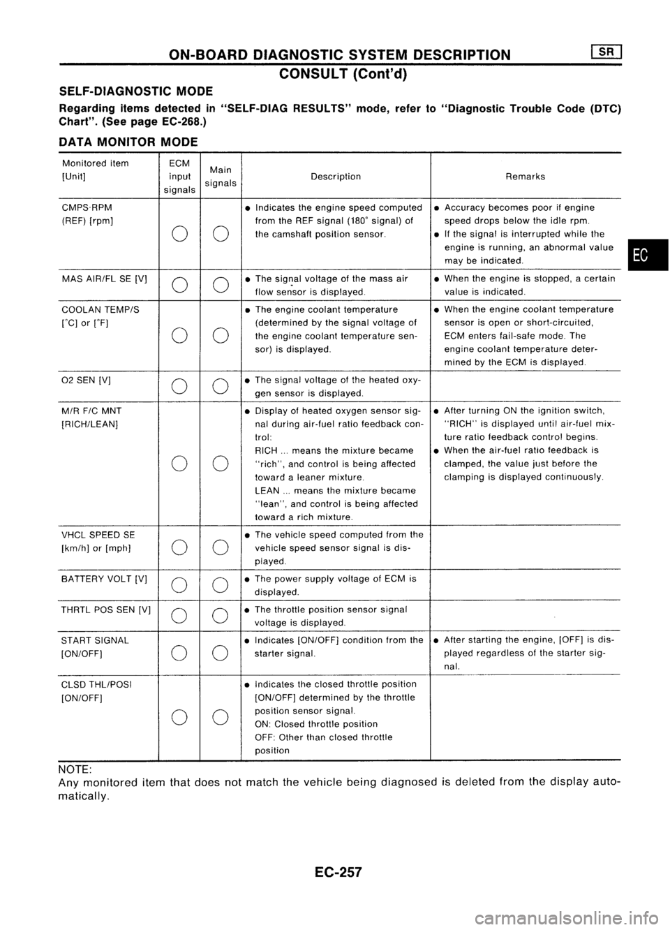
SELF-DIAGNOSTIC MODE
Regarding itemsdetected in"SELF-DiAG RESULTS"mode,referto"Diagnostic TroubleCode(DTC)
Chart". (Seepage EC-268.)
DATA MONITOR MODE
Monitored item ECM
Main
[Unit] input
signals Description
Remarks
signals
CMPS.RPM •Indicates theengine speedcomputed •
Accuracy becomespoorifengine
(REF) [rpm] fromtheREF signal (180'signal) of speeddropsbelow theidle rpm.
0 0
the
camshaft positionsensor. •
Ifthe signal isinterrupted whilethe
engine isrunning, anabnormal value
may beindicated .
MAS AIR/FL SE[V]
0 0
•
The sig~al voltage ofthe mass air •
When theengine isstopped, acertain
flow sensor isdisplayed. valueisindicated .
COOLAN TEMP/S •
The engine coolant temperature •
When theengine coolant temperature
rOC] orrF] (determined
bythe signal voltage ofsensor
isopen orshort-circuited,
0 0
the
engine coolant temperature sen-ECMenters fail-safe mode.The
sor) isdisplayed. engine
coolant temperature deter-
mined bythe ECM isdisplayed .
02
SEN [V]
00
•
The signal voltage ofthe heated oxy-
gen sensor isdisplayed.
M/R F/CMNT •
Display ofheated oxygen sensorsig-•
After turning ONthe ignition switch,
[RICH/LEAN] nal
during air-fuel ratiofeedback con-"RICH"
isdisplayed untilair-fuel mix-
trol: ture
ratio feedback controlbegins.
RICH ...means themixture became •
When theair-fuel ratiofeedback is
0 0
"rich",
andcontrol isbeing affected clamped,
thevalue justbefore the
toward aleaner mixture. clamping
isdisplayed continuously.
LEAN ...means themixture became
"lean", andcontrol isbeing affected
toward arich mixture .
VHCL SPEED SE •
The vehicle speedcomputed fromthe
[km/h] or[mph]
00
vehicle
speedsensor signalisdis-
played .
SA TTERY VOLT[V]
0 0
•
The power supply voltage ofECM is
displayed .
THRTL POSSEN [V]
0 0
•
The throttle position sensorsignal
voltage isdisplayed.
START SIGNAL •
Indicates [ON/OFF] conditionfromthe•
After starting theengine, [OFF]isdis-
[ON/OFF]
00
starter
signal. played
regardless ofthe starter sig-
nal.
CLSD THLIPOSI •
Indicates theclosed throttle position
[ON/OFF] [ON/OFF]
determined bythe throttle
0 0
position
sensorsignal.
ON: Closed throttle position
OFF: Other thanclosed throttle
position
NOTE:
Any monitored itemthatdoes notmatch thevehicle beingdiagnosed isdeleted fromthedisplay auto-
matically.
EC-257
•
Page 978 of 1701

ON-BOARDDIAGNOSTIC SYSTEMDESCRIPTION
CONSULT (Conl'd)
ACTIVE TESTMODE
TEST ITEM CONDITION JUDGEMENTCHECKITEM(REMEDY)
• Engine: Returntothe original
•Harness andconnector
FUEL INJECTION trouble
condition
Iftrouble symptom disappears,
•Fuel injectors
• Change theamount offuel
seeCHECK ITEM.
•Heated oxygen sensor
injection usingCONSULT .
• Engine: Afterwarming up,idle
IACV-AACIV the
engine.
Enginespeedchanges according •Harness andconnector
OPENING •
Change theIACV-AAC valve
tothe opening percent. •
IACV-AAC valve
opening percentusingCON-
SULT.
• Engine: Returntothe original
•Harness andconnector
ENG COOLANT trouble
condition
Iftrouble symptom disappears, •
Engine coolant temperature
• Change theengine coolant
.
TEMP see
CHECK ITEM. sensor
temperature indicationusing
•Fuel injectors
CONSULT .
• Engine: Returntothe original
trouble condition
Iftrouble symptom disappears,
IGNITION TIMING•Timing light:Set •
Adjust initialignition timing
• Retard theignition timingusingsee
CHECK ITEM.
CONSULT.
• Engine: Afterwarming up,idle •
Harness andconnector
the engine. •
Compression
POWER
•
AIC
switch "OFF"
Enginerunsrough ordies. •
Injectors
BALANCE •
Shift lever "N" •
Power transistor
• Cut offeach injector signalone •
Spark plugs
at atime using CONSULT . •
Ignition coils
• Ignition switch:ON
•Harness andconnector
COOLING FAN•
Turn thecooling fan"ON" andCooling
fanmoves andstops.
•Cooling fanmotor
"OFF" usingCONSULT .
• Ignition switch:ON(Engine
FUEL PUMP stopped)
Fuelpump relaymakes theoper- •
Harness andconnector
RELAY •
Turn thefuel pump relay"ON"
atingsound. •
Fuel pump relay
and "OFF" usingCONSULT
and listen tooperating sound.
EGRC •
Ignition switch:ON
• Turn solenoid valve"ON"and Solenoid
valvemakes anoperat- •
Harness andconnector
SOLENOID "OFF"withtheCONSULT andingsound. •
Solenoid valve
VALVE listentooperating sound.
SELF-LEARNING •
In this test, thecoefficient ofself-learning controlmixture ratioreturns tothe original coefficient by
CONT touching
"CLEAR" onthe screen.
EC-259
•
Page 979 of 1701
ON-BOARDDIAGNOSTIC SYSTEMDESCRIPTION
CONSULT (Conl'd)
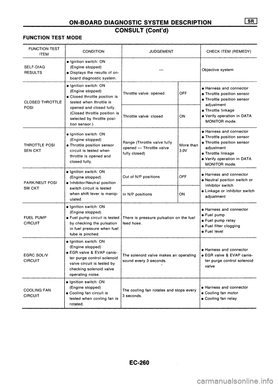
FUNCTION TESTMODE
FUNCTION TEST
CONDITION JUDGEMENTCHECKITEM(REMEDY)
ITEM
•Ignition switch:ON
SELF-DIAG (Enginestopped)
Objectivesystem
-
RESULTS •Displays theresults ofon-
board diagnostic system.
• Ignition switch:ON
•Harness andconnector
(Engine stopped)
Throttlevalve:opened OFF
•Throttle position sensor
• Closed throttle position is
•Throttle position sensor
CLOSED THROTTLE testedwhenthrottle is
POSI opened
andclosed fully. adjustment
• Throttle linkage
(Closed throttleposition is
Throttle valve:closed
ON•
Verify operation inDATA
selected bythrottle posi-
MONITORmode.
tion sensor.)
• Ignition switch:ON •
Harness andconnector
• Throttle position sensor
(Engine stopped)
Range(Throttle valvefully •Throttle position sensor
THROTTLE POSI•Throttle position sensor
opened-Throttle valve More
than
adjustment
SEN CKT circuitistested when 3.QV
throttle isopened and fully
closed) •Throttle linkage
• Verify operation inDATA
closed fully.
MONITORmode.
• Ignition switch:ON
•Harness andconnector
(Engine stopped) Out
ofN/P positions OFF
PARK/NEUT POSI•Inhibitor/Neutral position •
Neutral position switchor
SW CKT switch
circuit istested inhibitor
switch
when shiftlever ismanip-
InN/P positions ON•
Linkage orinhibitor switch
ulated . adjustment
• Ignition. switch:ON
•Harness andconnector
(Engine stopped)
•Fuel pump
FUEL PUMP •Fuel pump circuit istested
Thereispressure pulsation onthe fuel
•Fuel pump relay
CIRCUIT bychecking thepulsation feedhose.
in fuel pressure whenfuel •
Fuel filter clogging
tube ispinched . •
Fuel level
• Ignition switch:ON
(Engine stopped)
•Harness andconnector
EGRC SOLIV •
EGR valve
&
EVAP canis-
Thesolenoid valvemakes anoperating •
EGR valve
&
EVAP canis-
CIRCUIT ter
purge control solenoid
soundevery3seconds. terpurge control solenoid
valve circuit istested by
.
valve
checking solenoidvalve
operating noise.
• Ignition switch:ON
COOLING FAN (Engine
stopped)
Thecooling fanrotates andstops every •
Harness andconnector
• Cooling fancircuit is •Cooling fanmotor
CIRCUIT testedwhencoaling fanis3
seconds.
•Cooling fanrelay
rotated.
EC-260
Page 982 of 1701
ON-BOARDDIAGNOSTIC SYSTEMDESCRIPTION
CONSULT (Cont'd)
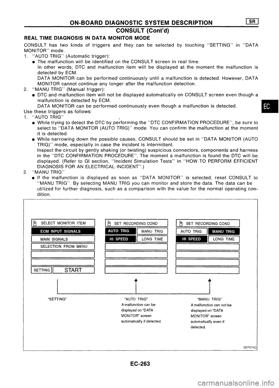
REAL TIMEDIAGNOSIS INDATA MONITOR MODE
CONSULT hastwo kinds oftriggers andthey canbeselected bytouching "SETTING" in"DATA
MONITOR" mode.
1. "AUTO TRIG"(Automatic trigger):
• The malfunction willbeidentified onthe CONSULT screeninreal time.
In other words, DTCandmalfunction itemwillbedisplayed atthe moment themalfunction is
detected byECM.
DATA MONITOR canbeperformed continuously untilamalfunction isdetected. However, DATA
MONITOR cannotcontinue anylonger afterthemalfunction detection.
2. "MANU TRIG"(Manual trigger):
• DTC andmalfunction itemwillnotbedisplayed automatically onCONSULT screeneventhough a
malfunction isdetected byECM. •
DATA MONITOR canbeperformed continuously eventhough amalfunction isdetected.
Use these triggers asfollows:
1. "AUTO TRIG"
• While trying todetect theDTC byperforming the"DTC CONFIRMATION PROCEDURE",besure to
select to"DATA MONITOR (AUTOTRIG)" mode.Youcanconfirm themalfunction atthe moment
it is detected .
• While narrowing downthepossible causes,CONSULT shouldbeset in"DATA MONITOR (AUTO
TRIG)" mode,especially incase theincident isintermittent.
Inspect thecircuit bygently shaking (ortwisting) suspicious connectors, components andharness
in the "DTC CONFIRMATION PROCEDURE".Themoment amalfunction isfound theDTC willbe
displayed. (RefertoGI section, "Incident Simulation Tests"in"HOW TOPERFORM EFFICIENT
DIAGNOSIS FORANELECTRICAL INCIDENT".)
2. "MANU TRIG"
• Ifthe malfunction isdisplayed assoon as"DATA MONITOR" isselected, resetCONSULT to
"MANU TRIG".Byselecting MANUTRIGyoucan monitor andstore thedata. Thedata canbe
utilized forfurther diagnosis, suchasacomparison withthevalue forthe normal operating con-
dition.
ECM INPUT SIGNALS
HISPEED
AUTO
TRIG
I
~
SELECT MONITOR ITEM
I
MAIN SIGNALS
I
SELECTION FROMMENU
1 _
1========
l-SE-TI-IN-G
ll--S-T.-AR-T--
I
~
SET RECORDING COND
I
MANU TRIG
I
LONG TIME HI
SPEED MANU
TRIG
__ 1__ J
"SETIING" "AUTOTRIG"
A malfunction canbe
displayed on"DATA
MONITOR" screen
automatically ifdetected.
EC-263 "MANU
TRIG"
A malfunction cannotbe
displayed on"DATA
MONITOR" screen
automatically evenif
detected.
SEF6740
Page 985 of 1701
STEP
STEP I
STEP II
STEP III
STEP IV
STEP V
STEP VI
STEP VII
TROUBLE
DIAGNOSIS -General Description
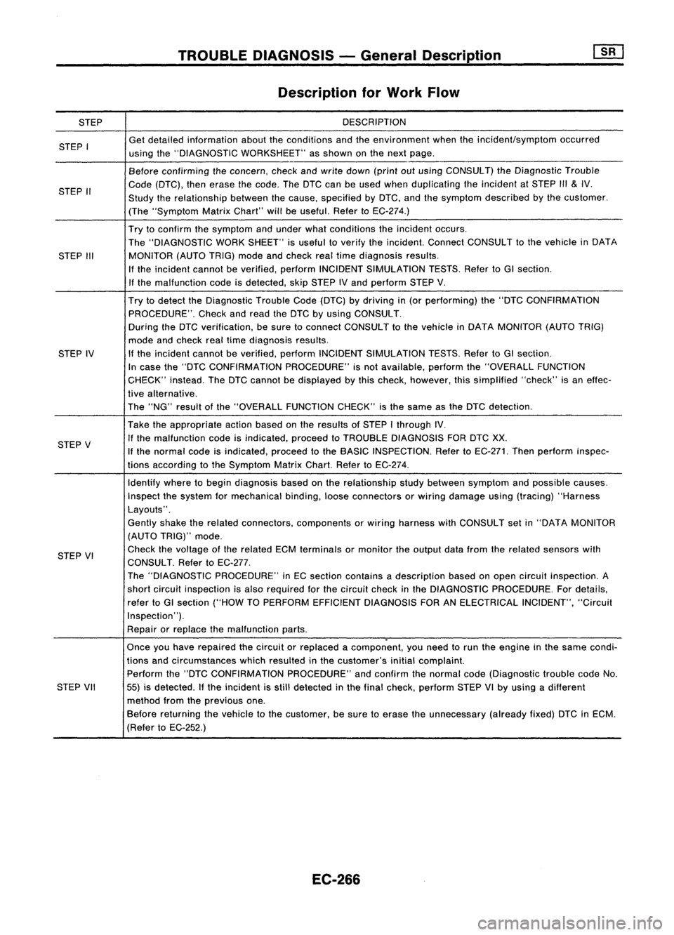
Description forWork Flow
DESCRIPTION
Get detailed information abouttheconditions andtheenvironment whentheincident/symptom occurred
using the"DIAGNOSTIC WORKSHEET" asshown onthe next page.
Before confirming theconcern, checkandwrite down (printoutusing CONSULT) theDiagnostic Trouble
Code (DTC), thenerase thecode. TheDTC canbeused when duplicating theincident atSTEP
1/1
&
IV.
Study therelationship betweenthecause, specified byDTC, andthesymptom described bythe customer.
(The "Symptom MatrixChart" willbeuseful. RefertoEC-274.)
Try toconfirm thesymptom andunder whatconditions theincident occurs.
The "DIAGNOSTIC WORKSHEET" isuseful toverify theincident. ConnectCONSULT tothe vehicle inDATA
MONITOR (AUTOTRIG)modeandcheck realtime diagnosis results.
If the incident cannotbeverified, performINCIDENT SIMULATION TESTS.RefertoGI section.
If the malfunction codeisdetected, skipSTEP IVand perform STEPV.
Try todetect theDiagnostic TroubleCode(DTC) bydriving in(or performing) the"DTC CONFIRMATION
PROCEDURE". Checkandread theDTC byusing CONSULT.
During theDTC verification, besure toconnect CONSULT tothe vehicle inDATA MONITOR (AUTOTRIG)
mode andcheck realtime diagnosis results.
If the incident cannotbeverified, performINCIDENT SIMULATION TESTS.RefertoGI section.
In case the"DTC CONFIRMATION PROCEDURE"isnot available, performthe"OVERALL FUNCTION
CHECK" instead.TheDTC cannot bedisplayed bythis check, however, thissimplified "check"isan effec-
tive alternative.
The "NG" result ofthe "OVERALL FUNCTIONCHECK"isthe same asthe DTC detection.
Take theappropriate actionbasedonthe results ofSTEP Ithrough IV.
If the malfunction codeisindicated, proceedtoTROUBLE DIAGNOSIS FORDTCXX.
If the normal codeisindicated, proceedtothe BASIC INSPECTION. RefertoEC-271. Thenperform inspec-
tions according tothe Symptom MatrixChart.RefertoEC-274.
Identify wheretobegin diagnosis basedonthe relationship studybetween symptom andpossible causes.
Inspect thesystem formechanical binding,looseconnectors orwiring damage using(tracing) "Harness
Layouts".
Gently shaketherelated connectors, components orwiring harness withCONSULT setin"DATA MONITOR
(AUTO TRIG)" mode.
Check thevoltage ofthe related ECMterminals ormonitor theoutput datafrom therelated sensors with
CONSULT. RefertoEC-277.
The "DIAGNOSTIC PROCEDURE" inEC section contains adescription basedonopen circuit inspection. A
short circuit inspection isalso required forthe circuit checkinthe DIAGNOSTIC PROCEDURE. Fordetails,
refer toGI section ("HOWTOPERFORM EFFICIENT DIAGNOSIS FORANELECTRICAL INCIDENT","Circuit
Inspection").
Repair orreplace themalfunction parts.
.
Once youhave repaired thecircuit orreplaced acomponent, youneed torun theengine inthe same condi-
tions andcircumstances whichresulted inthe customer's initialcomplaint.
Perform the"DTC CONFIRMATION PROCEDURE"andconfirm thenormal code(Diagnostic troublecodeNo.
55) isdetected. Ifthe incident isstill detected inthe final check, perform STEPVIby using adifferent
method fromtheprevious one.
Before returning thevehicle tothe customer, besure toerase theunnecessary (alreadyfixed)DTCinECM.
(Refer toEC-252.)
EC-266
Page 987 of 1701
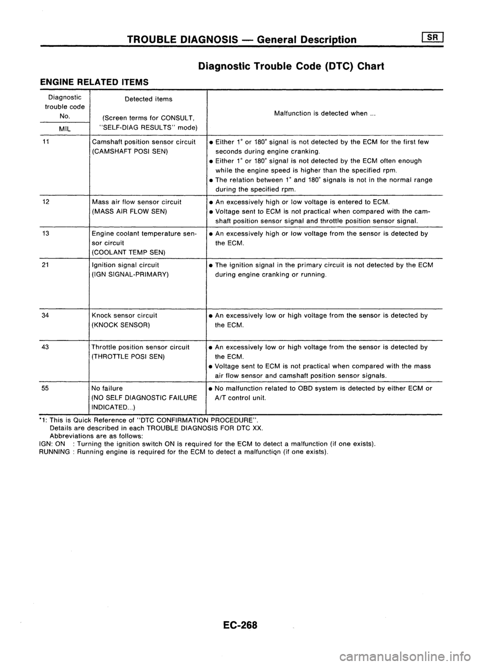
TROUBLEDIAGNOSIS -General Description
Diagnostic TroubleCode(DTC) Chart
ENGINE RELATED ITEMS
Diagnostic Detecteditems
trouble code
No. (ScreentermsforCONSULT, Malfunction
isdetected when...
MIL "SELF-DIAG
RESULTS"mode)
11
Camshaftpositionsensorcircuit •Either
1
0
or
180
0
signal isnot detected bythe ECM forthe first few
(CAMSHAFT POSISEN) secondsduringengine cranking .
• Either
1
0
or
180
0
signal isnot detected bythe ECM often enough
while theengine speedishigher thanthespecified rpm.
• The relation between
1"
and
180"
signals isnot inthe normal range
during thespecified rpm.
12
Massairflow sensor circuit
•An excessively highorlow voltage isentered toECM.
(MASS AIRFLOW SEN) •Voltage senttoECM isnot practical whencompared withthecam-
shaft position sensorsignalandthrottle position sensorsignal.
13
Enginecoolant temperature sen-•An excessively highorlow voltage fromthesensor isdetected by
sor circuit theECM.
(COOLANT TEMPSEN)
21
Ignitionsignalcircuit
•The ignition signalinthe primary circuitisnot detected bythe ECM
(IGN SIGNAL-PRIMARY)
duringengine cranking orrunning.
34
Knocksensor circuit •An excessively loworhigh voltage fromthesensor isdetected by
(KNOCK SENSOR) theECM .
43
Throttlepositionsensorcircuit •
An excessively loworhigh voltage fromthesensor isdetected by
(THROTTLE POSISEN)
theECM.
• Voltage senttoECM isnot practical whencompared withthemass
air flow sensor andcamshaft positionsensorsignals.
55
Nofailure •No malfunction relatedtoOBD system isdetected byeither ECMor
(NO SELF DIAGNOSTIC FAILURE
AIT
control unit.
INDICATED ...)
*1: This isQuick Reference of"DTC CONFIRMATION PROCEDURE".
Details aredescribed ineach TROUBLE DIAGNOSIS FORDTC
XX.
Abbreviations areasfollows:
IGN: ON :Turning theignition switchONisrequired forthe ECM todetect amalfunction (ifone exists).
RUNNING: Runningengineisrequired forthe ECM todetect amalfunctiQn (ifone eXists).
EC-268
Page 989 of 1701
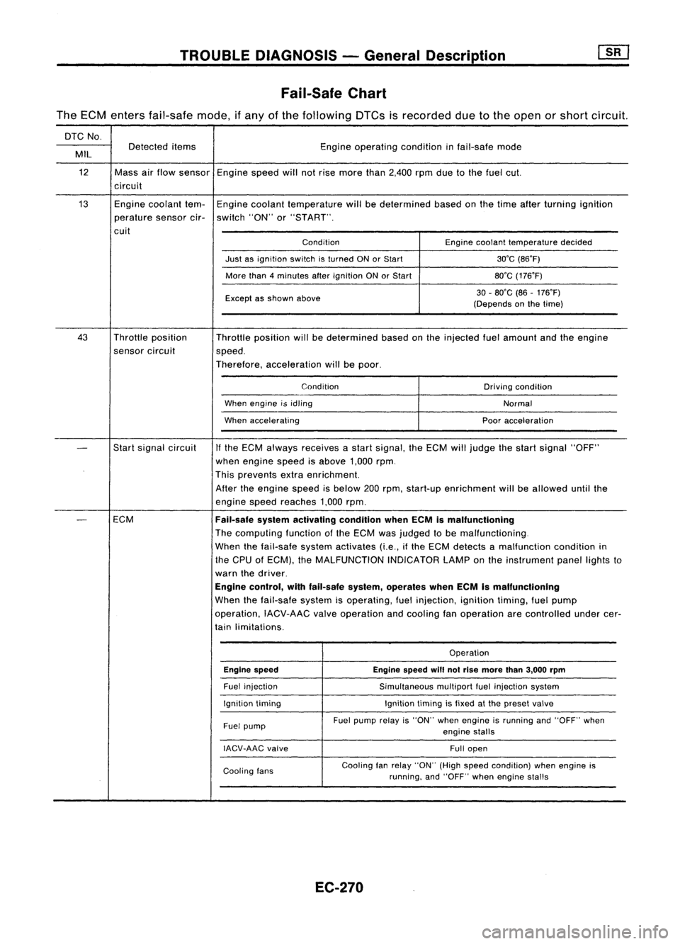
TROUBLEDIAGNOSIS -General Description
Fail-Safe Chart
The ECM enters fail-safe mode,ifany ofthe following DTCsisrecorded duetothe open orshort circuit.
DTC No.
Detected items Engineoperating conditioninfail-safe mode
MIL
12 Massairflow sensor Enginespeedwillnotrise more than2,400 rpmduetothe fuel cut.
circuit
13 Enginecoolant tem-Engine coolant temperature willbedetermined basedonthe time after turning ignition
perature sensorcir-switch "ON"or"START".
cuit ConditionEnginecoolant temperature decided
Just asignition switchisturned ONorStart 30'C(86'F)
More than4minutes afterignition ONorStart 80'C(176'F)
Except asshown above 30
-80'C (86-176'F)
(Depends onthe time)
43 Throttle position
Throttleposition willbedetermined basedonthe injected fuelamount andtheengine
sensor circuit
speed.
Therefore, acceleration willbepoor.
Condition Drivingcondition
When engine i$idling
Normal
When accelerating Pooracceleration
-
Start
signal circuit
If
the ECM always receives astart signal, theECM willjudge thestart signal "OFF"
when engine speedisabove 1,000rpm.
This prevents extraenrichment.
After theengine speedisbelow 200rpm, start-up enrichment willbeallowed untilthe
engine speedreaches 1,000rpm.
-
ECM
Fail-safesystemactivating conditionwhenECMismalfunctioning
The computing functionofthe ECM wasjudged tobe malfunctioning.
When thefail-safe systemactivates (i.e.,ifthe ECM detects amalfunction conditionin
the CPU ofECM), theMALFUNCTION INDICATORLAMPonthe instrument panellightsto
warn thedriver.
Engine control, withfail-safe system,operates whenECMismalfunctioning
When thefail-safe systemisoperating, fuelinjection, ignitiontiming,fuelpump
operation, IACV-AACvalveoperation andcooling fanoperation arecontrolled undercer-
tain limitations.
Operation
Engine speed Enginespeedwillnotrise more than3,000 rpm
Fuel injection
Simultaneousmultiportfuelinjection system
Ignition timing Ignitiontimingisfixed atthe preset valve
Fuel pump Fuel
pump relayis"ON" whenengine isrunning and"OFF" when
engine stalls
IACV-AAC valve
Fullopen
Cooling fans Cooling
fanrelay "ON" (Highspeed condition) whenengine is
running, and"OFF" whenengine stalls
EC-270
Page 990 of 1701
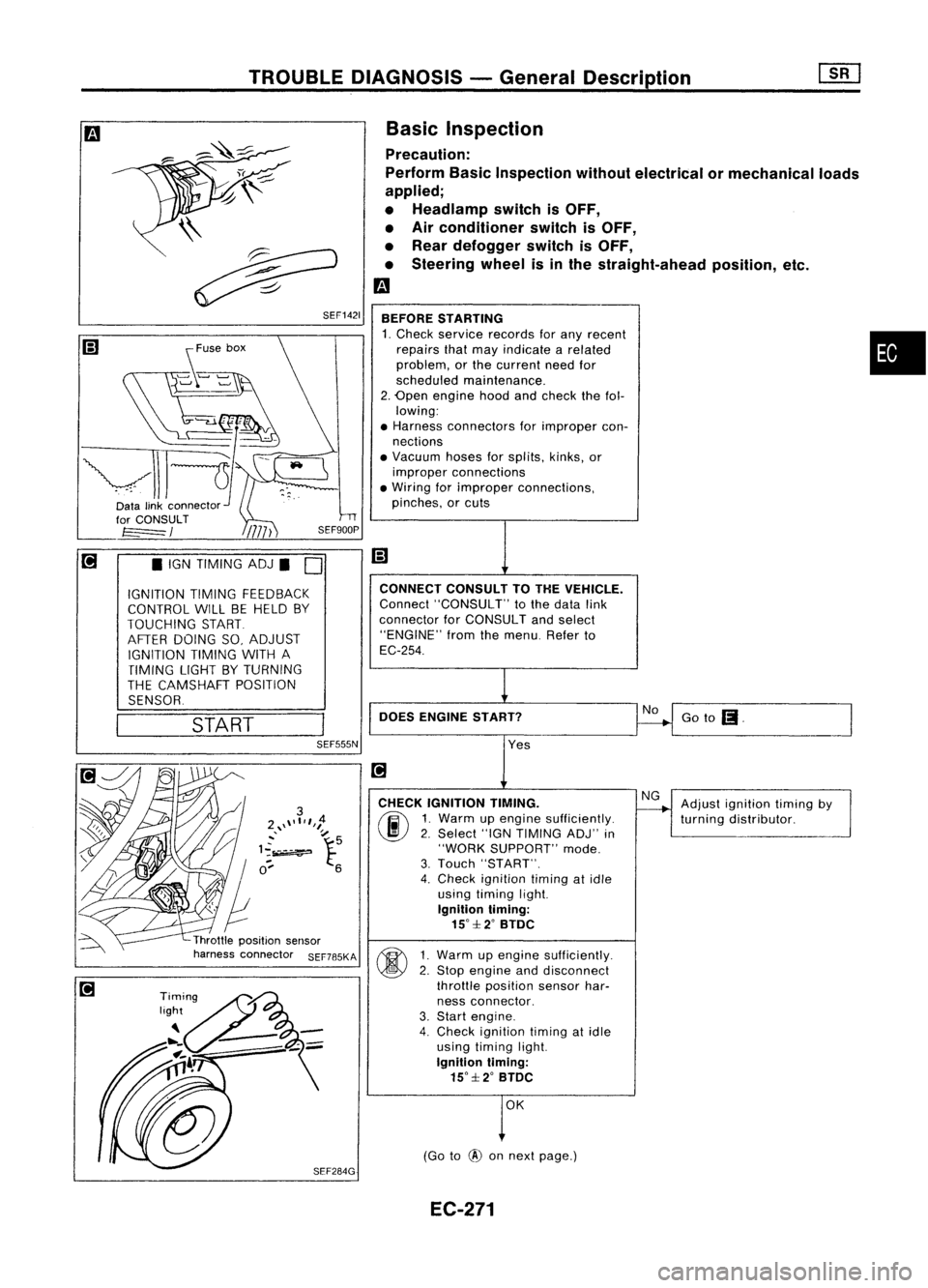
TROUBLEDIAGNOSIS -General Descrip_ti_on
1S_R_'
Basic Inspection
Precaution:
Perform BasicInspection withoutelectrical ormechanical loads
applied;
• Headlamp switchisOFF,
• Air conditioner switchisOFF,
• Rear defogger switchisOFF,
• Steering wheelisinthe straight-ahead position,etc.
m
BEFORE STARTING
1. Check service records forany recent •
repairs thatmay indicate arelated
problem, orthe current needfor
scheduled maintenance.
2. Open engine hoodandcheck thefol-
lowing:
• Harness connectors forimproper con-
nections
• Vacuum hosesforsplits, kinks,or
improper connections
• Wiring forimproper connections,
pinches, orcuts
Goto
(I.
No
CONNECT
CONSULTTOTHE VEHICLE.
Connect "CONSULT" tothe data link
connector forCONSULT andselect
"ENGINE" fromthemenu. Referto
EC-254.
DOES ENGINE START?
\\
~
~ SEF1421
START
•
IGN TIMING ADJ.
0
IGNITION TIMINGFEEDBACK
CONTROL WILLBEHELD BY
TOUCHING START
AFTER DOING SO,ADJUST
IGNITION TIMINGWITHA
TIMING LIGHTBYTURNING
THE CAMSHAFT POSITION
SENSOR.
SEF555N
Yes
CHECK IGNITION TIMING.
(ij\
1.Warm upengine sufficiently.
~ 2.Select "IGNTIMING ADJ"in
"WORK SUPPORT" mode.
3. Touch "START".
4. Check ignition timingatidle
using timing light.
Ignition timing:
15°::f:2° BTDC
~ 1Warm upengine sufficiently.
~ 2:
Stop engine anddisconnect
throttle position sensorhar-
ness connector.
3. Start engine.
4. Check ignition timingatidle
using timing light.
Ignition timing:
15°::f:2° BTDC
OK
(Go to
@
onnext page.) Adjust
ignition timingby
turning distributor.
EC-271