Page 1053 of 1701
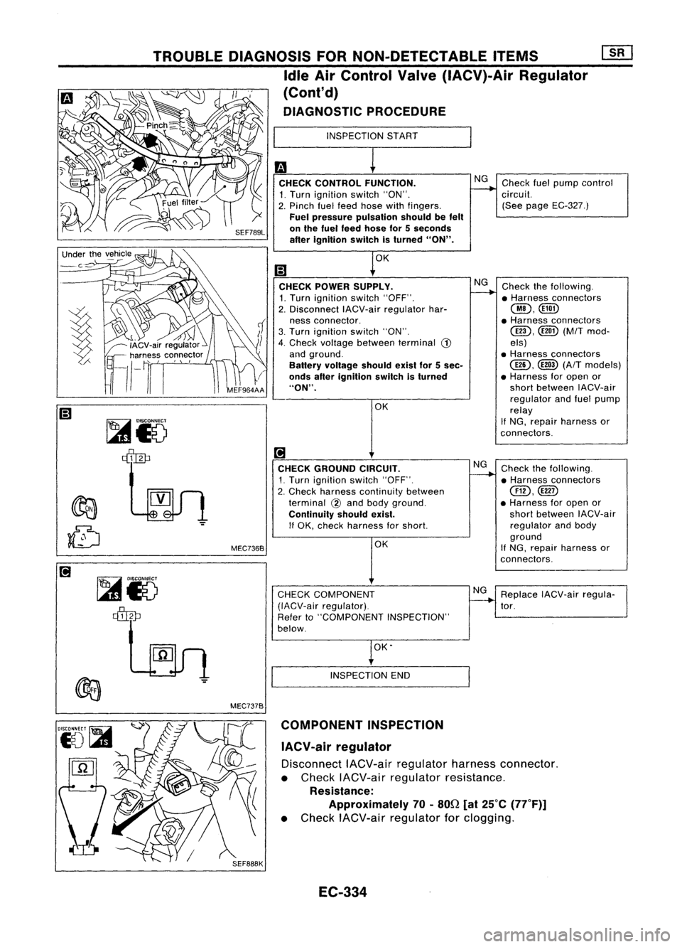
ReplaceIACV-air regula-
tor. Check
thefollowing.
• Harness connectors
Cill),
@ID
• Harness foropen or
short between IACV-air
regulator andbody
ground
If NG, repair harness or
connectors.
NG
I
INSPECTION
START
OK.
INSPECTION END
OK
CHECK
GROUND CIRCUIT.
1. Turn ignition switch"OFF".
2. Check harness continuity between
terminal
@
and body ground.
Continuity shouldexist.
If
OK, check harness forshort.
CHECK COMPONENT
(IACV-air regulator).
Refer to"COMPONENT INSPECTION"
below.
I
CHECK CONTROL FUNCTION. NG
Check fuelpump control
1. Turn ignition switch"ON".
~
circuit.
2. Pinch fuelfeed hose withfingers. (See
page EC-327.)
Fuel pressure pulsation shouldbefelt
on the fuel feed hose for5seconds
after ignition switchisturned "ON".
I;)
1
0K
CHECK POWER SUPPLY. NG
Check thefollowing.
1. Turn ignition switch"OFF".
~
•Harness connectors
2. Disconnect IACV-airregulator har-
@,@})
ness connector. •
Harness connectors
3. Turn ignition switch"ON".
@D,
(M/T
mod-
4. Check voltage between terminal
G)
els)
and ground. •Harness connectors
Battery voltage shouldexistfor5sec.
@,
@
(A/Tmodels)
onds afterignition switchisturned •
Harness foropen or
"ON". short
between IACV-air
OK regulator
andfuel pump
relay
If
NG, repair harness or
connectors.
MEC7368
TROUBLE
DIAGNOSIS FORNON-DETECTABLE ITEMS~
Idle AirControl Valve(IACV)-Air Regulator
(Cont'd)
DIAGNOSTIC PROCEDURE
~15
~
~
~15
~ ~
MEC7378COMPONENT INSPECTION
IACV-air regulator
Disconnect IACV-airregulator harnessconnector.
• Check IACV-air regulator resistance.
Resistance: Approximately
70•80n
[at25°C (77°F))
• Check IACV-air regulator forclogging.
EC-334
Page 1056 of 1701
•IGN TIMING ADJ.
0
TROUBLE
DIAGNOSIS FORNON-DETECTABLE ITEMS
[ill
Idle AirControl Valve(IACV) -Auxiliary Air
Control (AAC)Valve(Cont'd)
DIAGNOSTIC PROCEDURE
-- CONDITION SETIING--
IGN/T FEEDBACK HOLD INSPECTION
START
~i5 ~i5
ECM
E[CONNECTORII
cffb
113
=
= =
MONITOR
CAS. RPM (REF)
IGN TIMING
IDLE POSITION
---
---
800rpm
15BTDC
ON
SEF786KA
MEC768B CHECK
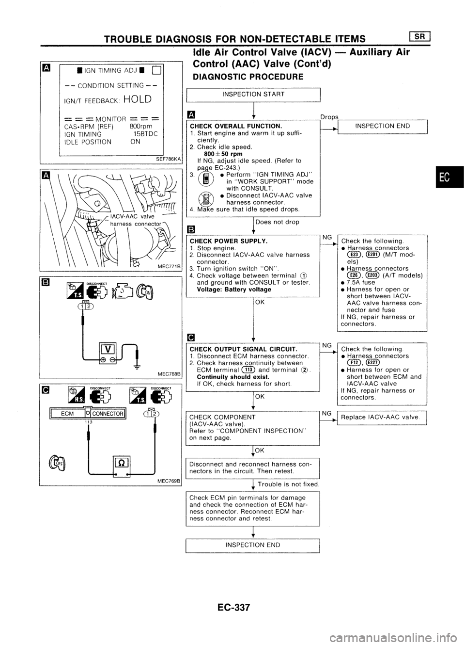
OVERALL FUNCTION.
1. Start engine andwarm itup suffi-
ciently.
2. Check idlespeed.
800::1:50
rpm
If NG, adjust idlespeed. (Referto
(l)
e
EC-243.)
3. .. •Perform "IGNTIMING ADJ"
I!I
in"WORK SUPPORT" mode
with CONSULT.
~ •Disconnect IACV-AACvalve
5
harness connector.
4. Ma esure thatidlespeed drops.
Does notdrop
CHECK POWER SUPPLY.
1. Stop engine.
2. Disconnect IACV-AACvalveharness
connector.
3. Turn ignition switch"ON".
4. Check voltage between terminal
G)
and ground withCONSULT ortester.
Voltage: Batteryvoltage
OK
[!1
CHECK OUTPUT SIGNALCIRCUIT.
1. Disconnect ECMharness connector.
2. Check harness continuity between
ECM terminal
CTID
andterminal
(2).
Continuity shouldexist.
If OK, check harness forshort
OK
CHECK COMPONENT
(IACV-AAC valve).
Refer to"COMPONENT INSPECTION"
on next page.
OK Drops
NG
NG
NG INSPECTION
END
Check thefollowing .
• Harness connectors
@D,
([ill)(M/Tmod-
els)
• Harness connectors
@,
@
(A/T
models)
• 7.5A fuse
• Harness foropen or
short between IACV-
AAC valve harness con-
nector andfuse
If NG, repair harness or
con nectors.
Check thefollowing.
• Harness connectors
@,@D
• Harness foropen or
short between ECMand
IACV-AAC valve
If
NG, repair harness or
connectors.
Replace IACV-AAC valve.
•
Disconnect andreconnect harnesscon-
nectors inthe circuit Thenretest
Trouble isnot fixed.
Check ECMpinterminals fordamage
and check theconnection ofECM har-
ness connector. ReconnectECMhar-
ness connector andretest
INSPECTION END
EC-337
Page 1062 of 1701
TROUBLEDIAGNOSIS FORNON-DETECTABLE ITEMS
Cooling FanControl
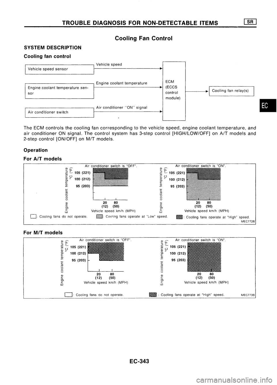
SYSTEM DESCRIPTION
Cooling fancontrol
I
Vehicle speedsensor
I
Vehicle speed
Engine coolant temperature EGM
Engine coolant temperature sen- (EGGS
~
sor control
module)
I
Air conditioner switch
I
Air conditio~er "ON"signal
I
Goaling fanrelay(s)
•
The ECM controls thecooling fancorresponding tothe vehicle speed,engine coolant temperature, and
air conditioner ONsignal. Thecontrol system has3-step control [HIGH/LOW/OFF] onA/T models and
2-step control [ON/OFF] onM/T models.
Operation
For AIT models
Airconditioner switchis"ON".
20 80
(12) (50)
Vehicle speedkm/h(MPH)
m!lll:
Cooling fansoperate at"High" speed.
MEC772B
~u:
~ ?-
105 (221)
~ 0
2i
0
100 (212)
E
2
95(203)
C
'"
o
o
o
20 80
OJ
(12) (50) .~
Vehicle speedkm/h(MPH) ~
~: Cooling fansoperate at"Low" speed.
~LL
.3
?-
105 (221)
~o
2i
0
100 (212)
E
2
95(203)
C
'"
o
o
o
OJ
c:
.0,
c
w
0:
Cooling fansdonot operate.
For MIT models
Airconditioner switchis"OFF".
2080
(12) (50)
Vehicle speedkm/h(MPH)
~
u:
Airconditioner switchis"ON".
::J
0
1il
Z;
105 (221)
OJ
0
E
100(212)
OJ
- 95(203)
C
'"
o
o
o
OJ
c
0,
c
ill
I
20 80
(12) (50)
Vehicle speedkm/h(MPH)
~u:
::J
0
1il ;-
105 (221)
OJ
0
~ 100(212)
<1>
- 95(203)
C
'"
o
o
o
OJ
c
.0,
c
ill
0:
COOling fansdonot operate. m
:Cooling fansoperate at"High" speed.
MEC773B
EC-343
Page 1065 of 1701
TROUBLEDIAGNOSIS FORNON-DETECTABLE ITEMS
Cooling FanControl (Cont'd)
• COOLING FANCIRCUIT.
DOES
COOLING FAN
ROTATE ANDSTOP
EVERY 3SECONDS
7
NEXT
II
NO
II
YES
I
MEF311F
• ACTIVE TEST.
0
COOLING FAN
OFF
= ==
MONITOR
==
=
COOLAN TEMP/S
HI
With airconditioner
C
k
00lin9fan
Q
~ID~
MEF277G
M/T
models
INSPECTION START
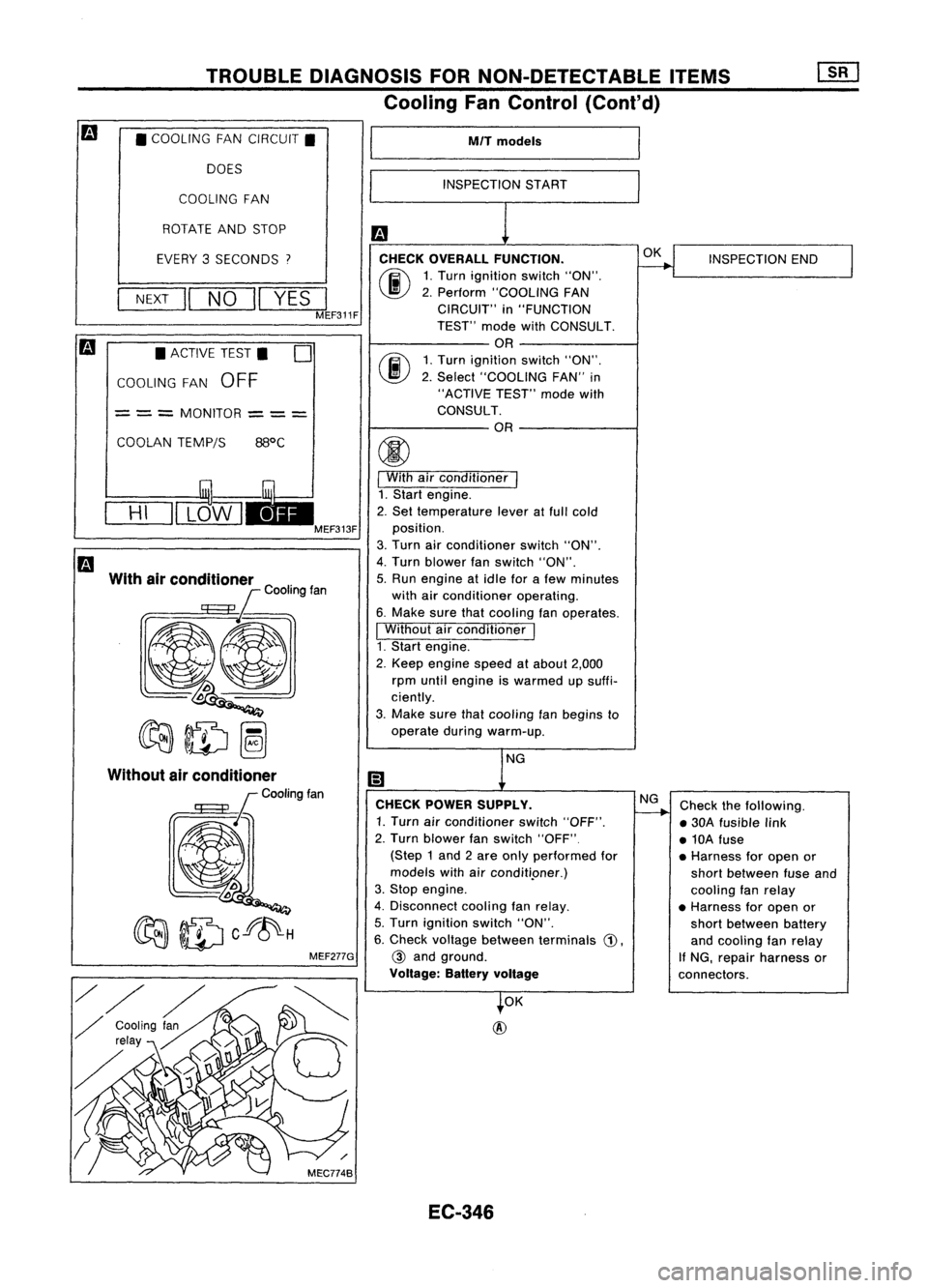
CHECK OVERALL FUNCTION.
(ij\
1.Turn ignition switch"ON".
~ 2.Perform "COOLING FAN
CIRCUIT" in"FUNCTION
TEST" modewithCONSULT.
OR
rij\
1.Turn ignition switch"ON".
\J!V
2.Select "COOLING FAN"in
"ACTIVE TEST"modewith
CONSULT.
OR
I
With airconditioner
I
1. Start engine.
2. Set temperature leveratfull cold
position.
3. Turn airconditioner switch"ON".
4. Turn blower fanswitch "ON".
5. Run engine atidle forafew minutes
with airconditioner operating.
6. Make surethatcooling fanoperates.
I
Without airconditioner
I
1. Start engine.
2. Keep engine speedatabout 2,000
rpm until engine iswarmed upsuffi-
ciently.
3. Make surethatcooling fanbegins to
operate duringwarm-up.
NG
CHECK POWER SUPPLY.
1. Turn airconditioner switch"OFF".
2. Turn blower fanswitch "OFF"
(Step 1and 2are only performed for
models withairconditi.oner.)
3. Stop engine.
4. Disconnect coolingfanrelay.
5. Turn ignition switch"ON".
6. Check voltage between terminals
G),
@
and ground.
Voltage: Batteryvoltage
OK
@
EC-346 OK
NG
INSPECTION
END
Check thefollowing.
• 30A fusible link
• 10A fuse
• Harness foropen or
short between fuseand
cooling fanrelay
• Harness foropen or
short between battery
and cooling fanrelay
If NG, repair harness or
connectors.
Page 1067 of 1701
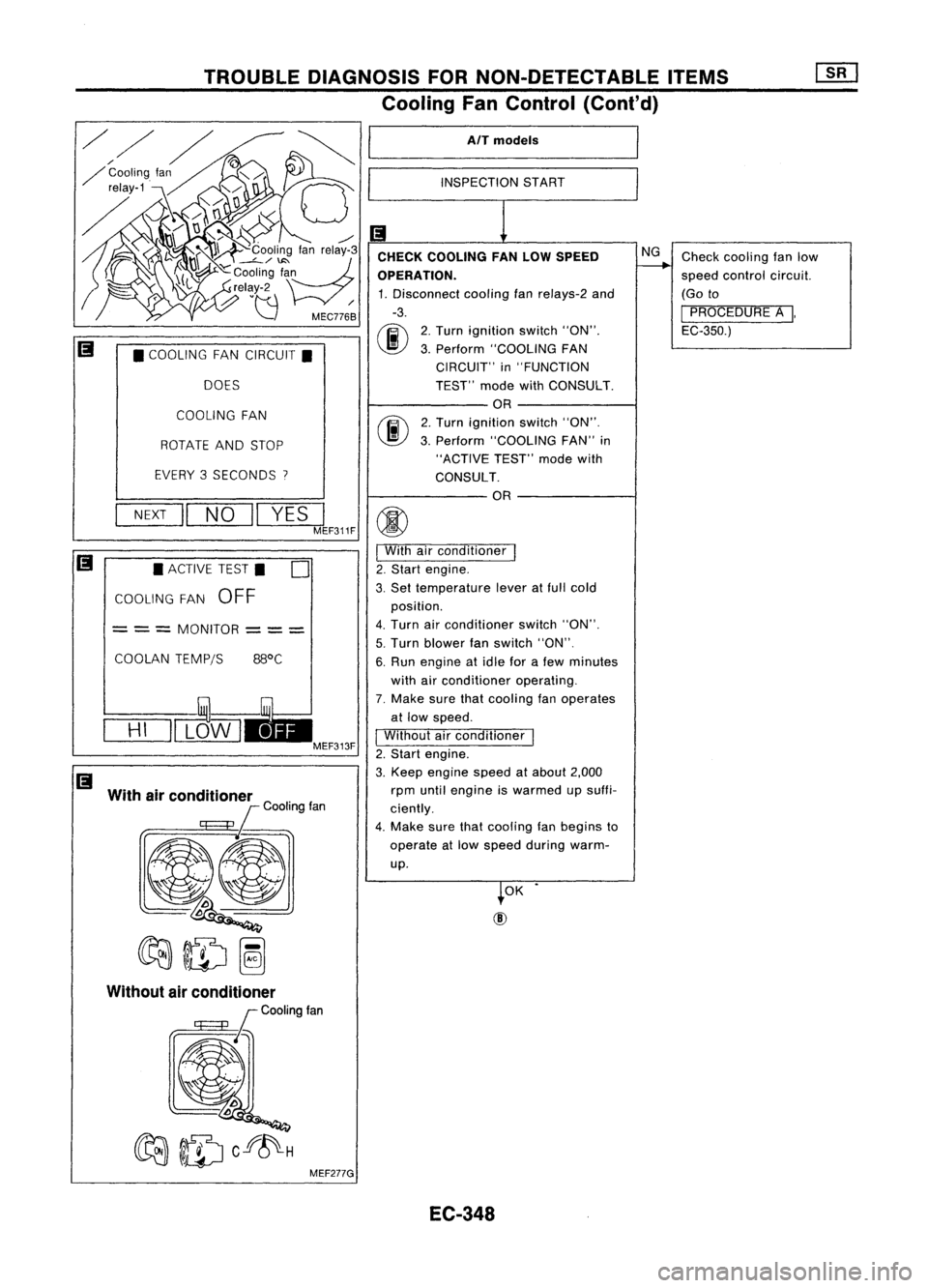
TROUBLEDIAGNOSIS FORNON-DETECTABLE ITEMS
Cooling FanControl (Cont'd)
AlT models
INSPECTION START
Checkcooling fanlow
speed control circuit.
(Go to
I
PROCEDURE A
I,
EC-350.)
NG
2. Turn ignition switch"ON".
3. Perform "COOLING FAN
CIRCUIT" in"FUNCTION
TEST" modewithCONSULT.
OR
2. Turn ignition switch"ON".
3. Perform "COOLING FAN"in
"ACTIVE TEST"modewith
CONSULT. OR
CHECK
COOLING FANLOW SPEED
OPERATION. 1. Disconnect coolingfan
re/ays-2
and
-3.
00
COOLING FAN
ROTATE ANDSTOP
EVERY 3SECONDS
I
•
COOLING FANCIRCUIT.
DOES
OK
NEXT
II
NO
II
YES
JF311F
(j)
I
With airconditioner
I
2. Start engine.
3. Set temperature leveratfull cold
position.
4. Turn airconditioner switch"ON".
5. Turn blower fanswitch "ON".
6. Run engine atidle forafew minutes
with airconditioner operating.
7. Make surethatcooling fanoperates
at low speed.
I
Without airconditioner
1
2. Start engine.
3. Keep engine speedatabout 2,000
rpm until engine iswarmed upsuffi-
ciently.
4. Make surethatcooling fanbegins to
operate atlow speed during warm-
up.
COOLAN
TEMPjS 88°C
•
ACTIVE TEST.
0
COOLING FAN
OFF
= ==
MONITOR
===
With airconditioner
lCOOtingfan
@l
~ID~
==H=I
=11L~W I
EC-348
Page 1068 of 1701
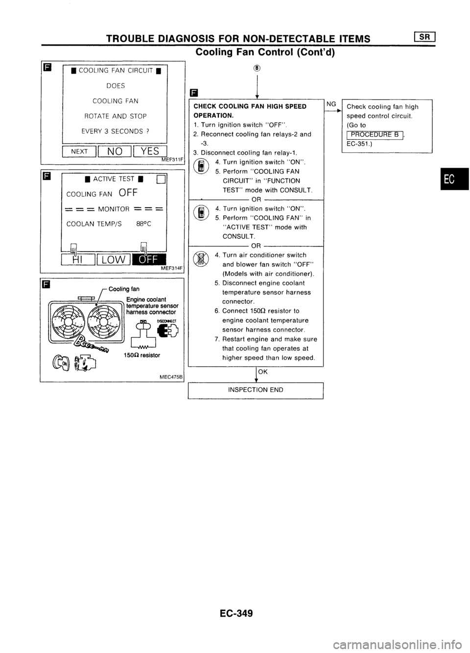
TROUBLEDIAGNOSIS FORNON-DETECTABLE ITEMS
Cooling FanControl (Cont'd)
• COOLING FANCIRCUIT.
DOES
Cooling fan
MEC475B
COOLING
FAN
•
Check
cooling fanhigh
speed control circuit.
(Go to
I
PROCEDURE B
I.
EC-351.)
NG
OK
CHECK
COOLING FANHIGH SPEED
OPERATION.
1. Turn ignition switch"OFF".
2. Reconnect coolingfanrelays-2 and
-3.
3. Disconnect coolingfanrelay-1.
(ij\
4.Turn ignition switch"ON".
~ 5.Perform "COOLING FAN
CIRCUIT" in"FUNCTION
TEST" modewithCONSULT.
OR
fiii\
4.Turn ignition switch"ON".
~ 5.Perform "COOLING FAN"in
"ACTIVE TEST"modewith
CONSULT.
OR
4. Turn airconditioner switch
and blower fanswitch "OFF"
(Models withairconditioner).
5. Disconnect enginecoolant
temperature sensorharness
connector.
6. Connect 150Qresistor to
engine coolant temperature
sensor harness connector.
7. Restart engineandmake sure
that cooling fanoperates at
higher speedthanlowspeed.
Ii
--- ---
150(1 resistor
ROTATE
ANDSTOP
EVERY 3SECONDS
"I
NEXT
II
NO
II
YES
I
MEF311F
COOLAN TEMP/S
•
ACTIVE TEST. D
COOLING FAN
OFF
= ==
MONITOR
clTJI
LOW
1.1-
MEF314F
Ii
Ii
INSPECTIONEND
EC-349
Page 1074 of 1701
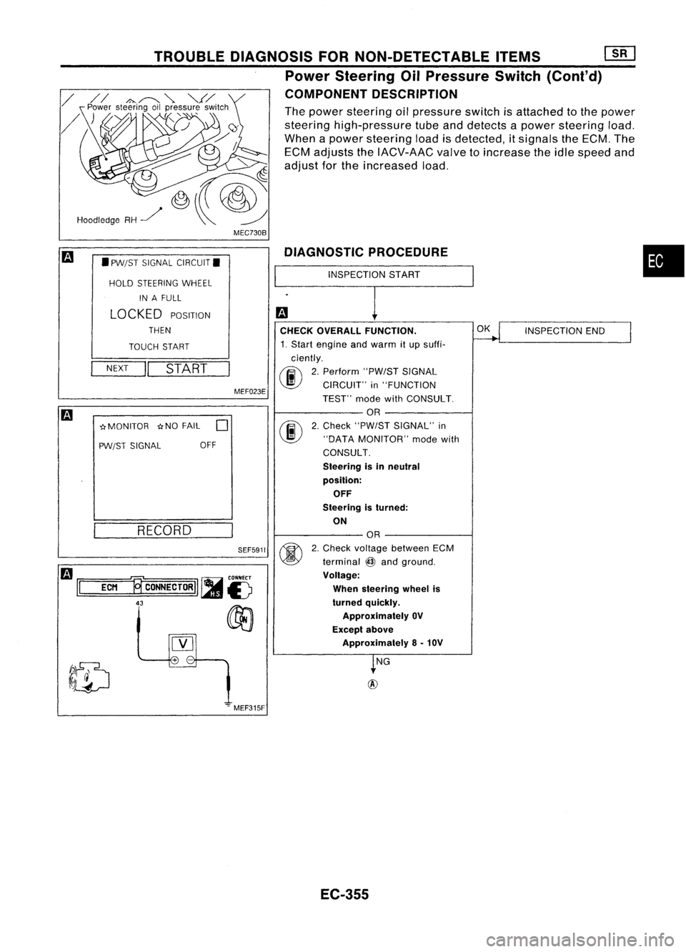
MEC730B
•
INSPECTION
START
DIAGNOSTIC
PROCEDURE
CHECK OVERALL FUNCTION.
~
INSPECTION
END
I
1. Start engine andwarm itup suffi-
ciently.
00
2.
Perform "PW/STSIGNAL
CIRCUIT" in"FUNCTION
TEST" modewithCONSULT.
OR
@
2.
Check "PW/ST SIGNAL" in
"DATA MONITOR" modewith
CONSULT.
Steering isin neutral
position: OFF
Steering isturned:
ON
OR
@
2.
Check voltage between ECM
terminal
@
and ground.
Voltage:
When steering wheelis
turned quickly.
Approximately OV
Except above
Approximately 8-10V
~NG
+
-
SEF5911
MEF023E
TROUBLE
DIAGNOSIS FORNON-DETECTABLE ITEMS[][]
Power Steering OilPressure Switch(Cont'd)
COMPONENT DESCRIPTION
The power steering oilpressure switchisattached tothe power
steering high-pressure tubeanddetects apower steering load.
When apower steering loadisdetected, itsignals theECM. The
ECM adjusts theIACV-AAC valvetoincrease theidle speed and
adjust forthe increased load.
RECORD
NEXT
II
START
•
PW/ST SIGNAL CIRCUIT.
HOLD STEERING WHEEL
IN AFULL
LOCKED
POSITION
THEN
TOUCH START
-crMONITOR -crNOFAIL
0
PW/ST SIGNAL OFF
Hoodledge
RH~
m
1='
=EC=M
=.,~
CONNECTORII ~
is
43
00
[Y]
.".MEF315F
EC-355
Page 1077 of 1701
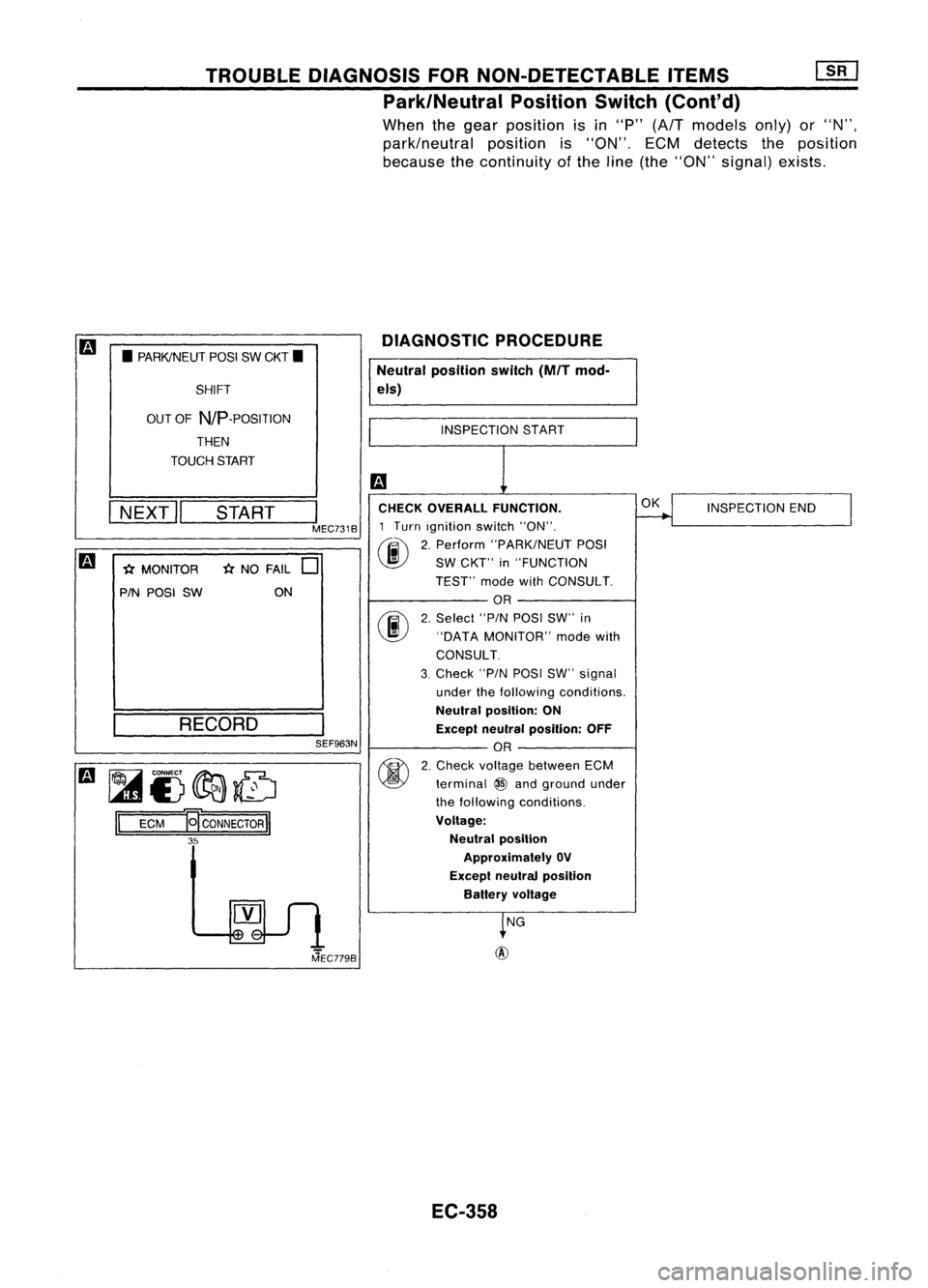
TROUBLEDIAGNOSIS FORNON-DETECTABLE ITEMS
[ill
Park/Neutral PositionSwitch(Cont'd)
When thegear position isin "P" (A/T models only)or"N",
park/neutral positionis"ON". ECMdetects theposition
because thecontinuity ofthe line (the "ON" signal) exists.
INSPECTION END
OK
NG
INSPECTION
8TART
DIAGNOSTIC
PROCEDURE
Neutral position switch
(M/T
mod-
els)
CHECK OVERALL FUNCTION.
1 Turn ignition switch"ON".
(Iii'"
2.Perform "PARK/NEUT POSI
~ SWCKT" in"FUNCTION
TEST" modewithCONSULT.
OR
(F.i\
2.Select "PINPOSI SW"in
\J!J
"DATAMONITOR" modewith
CONSULT.
3. Check "PINPOSI SW"signal
under thefollowing conditions.
Neutral position: ON
Except neulral posllion: OFF
SEF963N OR
~ 2.Check vo~ge between ECM
~ terminal~and ground under
the following conditions.
Voltage: Neutral position
Approximately OV
Excepl neutral position
Ballery voltage
m
•PARKINEUT POSISWCKT •
SHIFT
OUT OF
NIP
-POSITION
THEN
TOUCH START
I
NEXT
II
START
I
MEC731B
m
*MONITOR *NO FAIL
0
PIN POSI SW ON
RECORD
m ~
CONNECT~~
lAID£)~~
II
ECM
EcoNNECTORl1
35
MEC779B
EC-3S8