1995 NISSAN ALMERA N15 ECO mode
[x] Cancel search: ECO modePage 1399 of 1701
SAEJ1930 TERMINOLOGY LIST
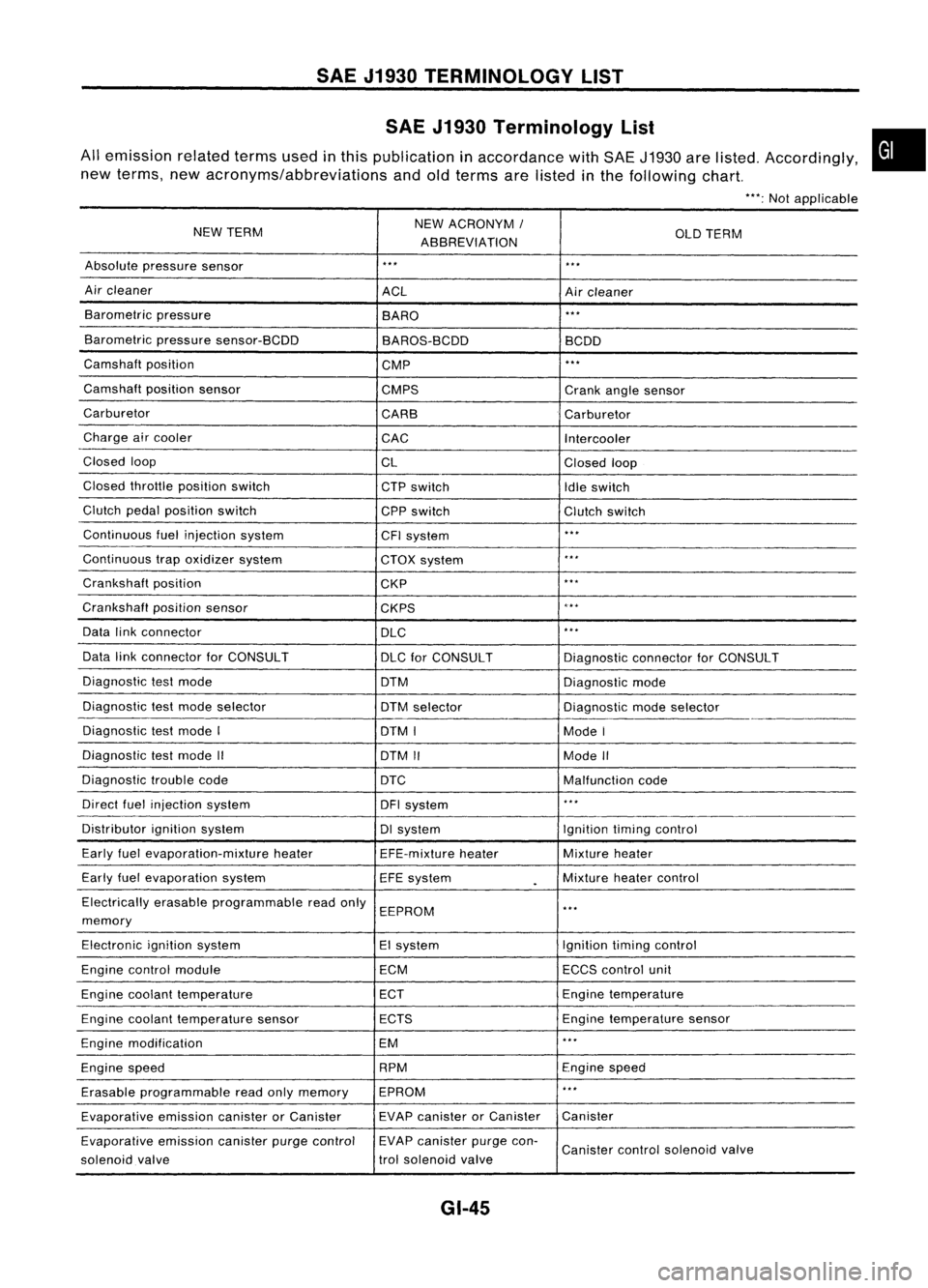
SAE J1930 Terminology List
All emission relatedtermsusedinthis publication inaccordance withSAE J1930 arelisted. Accordingly,
new terms, newacronyms/abbreviations andoldterms arelisted inthe following chart.
"':Not applicable
NEW TERM NEW
ACRONYM /
ABBREVIATION OLD
TERM
Absolute pressure sensor
'" '"
Air cleaner
ACLAircleaner
Barometric pressure
BARO
."
Barometric pressuresensor-BCDD
BAROS-BCDD BCDD
Camshaft position
CMP
'"
Camshaft positionsensor
CMPS Crankanglesensor
Carburetor CARBCarburetor
Charge aircooler
CACIntercooler
Closed loop
CLClosedloop
Closed throttle position switch
CTPswitch
Idleswitch
Clutch pedalposition switch
CPPswitch Clutchswitch
Continuous fuelinjection system
CFIsystem
'"
Continuous trapoxidizer system
CTOXsystem
...
Crankshaft position
CKP
'"
Crankshaft positionsensor
CKPS
~.**
Data linkconnector
DLC
,
..
Data linkconnector forCONSULT
DLCforCONSULT DiagnosticconnectorforCONSULT
Diagnostic testmode
DTMDiagnosticmode
Diagnostic testmode selector
DTMselector Diagnosticmodeselector
Diagnostic testmode I
DTMI ModeI
Diagnostic testmode II
DTMII ModeII
Diagnostic troublecode
DTC Malfunctioncode
Direct fuelinjection system
DFIsystem
..
,
Distributor ignitionsystem DIsystem Ignitiontimingcontrol
Early fuelevaporation-mixture heater
EFE-mixtureheater Mixture
heater
Early fuelevaporation system
EFEsystem
.
Mixture
heatercontrol
Electrically erasableprogrammable readonly
EEPROM
'"
memory
Electronic ignitionsystem EIsystem Ignitiontimingcontrol
Engine control module ECMECCScontrol unit
Engine coolant temperature ECTEngine
temperature
Engine coolant temperature sensor ECTS Engine
temperature sensor
Engine modification EM
'"
Engine speed RPM
Enginespeed
Erasable programmable readonlymemory EPROM
'"
Evaporative emissioncanisterorCanister EVAP
canister orCanister Canister
Evaporative emissioncanisterpurgecontrol EVAP
canister purgecon-
Canister controlsolenoid valve
solenoid valve trol
solenoid valve
GI-45
•
Page 1403 of 1701
HEATER
&
AIR CONDITIONER
SECTION
HA
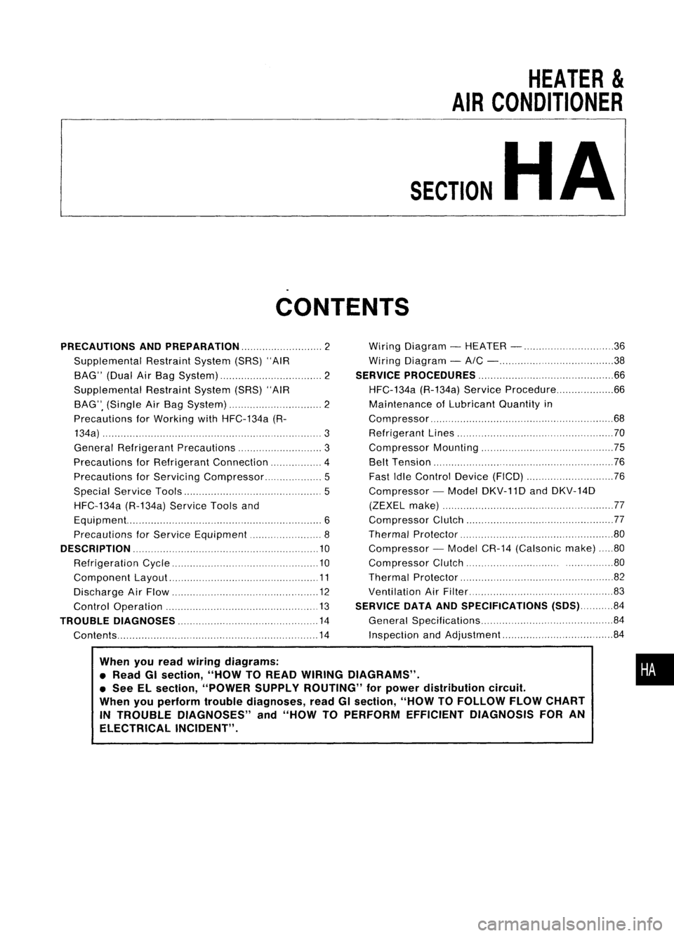
CONTENTS
When youread wiring diagrams:
• Read GIsection, "HOWTOREAD WIRING DIAGRAMS" .
• See ELsection, "POWER SUPPLYROUTING" forpower distribution circuit.
When youperform troublediagnoses, readGIsection, "HOWTOFOLLOW FLOWCHART
IN TROUBLE DIAGNOSES" and"HOW TOPERFORM EFFICIENT DIAGNOSIS FORAN
ELECTRICAL INCIDENT".
PRECAUTIONS
ANDPREPARATION 2
Supplemental RestraintSystem(SRS)"AIR
BAG" (DualAirBag System) 2
Supplemental RestraintSystem(SRS)"AIR
BAG", (Single AirBag System) 2
Precautions forWorking withHFC-134a (R-
134a) 3
General Refrigerant Precautions 3
Precautions forRefrigerant Connection 4
Precautions forServici ngCompressor. ..5
Special Service Tools 5
HFC-134a (R-134a)ServiceToolsand
Equipment. 6
Precautions forService Equipment 8
DESCRIPTION 10
Refrigeration Cycle .10
Component Layout 11
Discharge AirFlow 12
Control Operation 13
TROUBLE DIAGNOSES 14
Contents 14Wiring
Diagram -HEATER - 36
Wiring Diagram -
AIC - 38
SERVICE PROCEDURES 66
HFC-134a (R-134a)ServiceProcedure 66
Maintenance ofLubricant Quantityin
Compressor 68
Refrigerant Lines 70
Compressor Mounting 75
Belt Tension 76
Fast IdleControl Device(FICO) 76
Compressor -Model DKV-11D andDKV-14D
(ZEXEL make) 77
Compressor Clutch 77
Thermal Protector 80
Compressor -Model CR-14 (Calsonic make)80
Compressor Clutch ..80
Thermal Protector 82
Ventilation AirFilter 83
SERVICE DATAANDSPECIFICATIONS (SDS)84
General Specifications 84
Inspection andAdjustment 84
•
Page 1423 of 1701
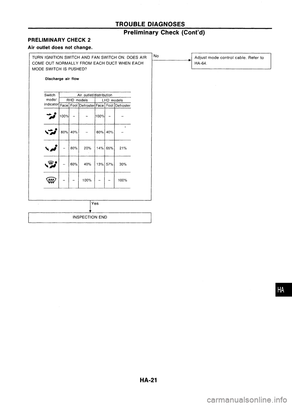
PRELIMINARY CHECK2
Air outlet doesnotchange. TROUBLE
DIAGNOSES
Preliminary Check(Cont'd)
TURN IGNITION SWITCHANDFANSWITCH ON.DOES AIR No
Adjustmodecontrol cable.Referto
COME OUTNORMALLY FROMEACHDUCTWHEN EACH HA-64.
MODE SWITCH ISPUSHED?
Discharge airflow
Switch Airoutlet/distribution
model RHOmodels
LHDmodels
indicator FaceFoot
Defroster FaceFoot
Defroster
iI
100%
-
-
100%
-
-
.
,7,./
60%40%
-
60%40%
-
,~
-
80%
20%14%65% 21%
,~
-
60% 40%
13%57% 30%
\tEl
-
-
100%
-
-
100%
res
INSPECTION END
HA-21
•
Page 1424 of 1701
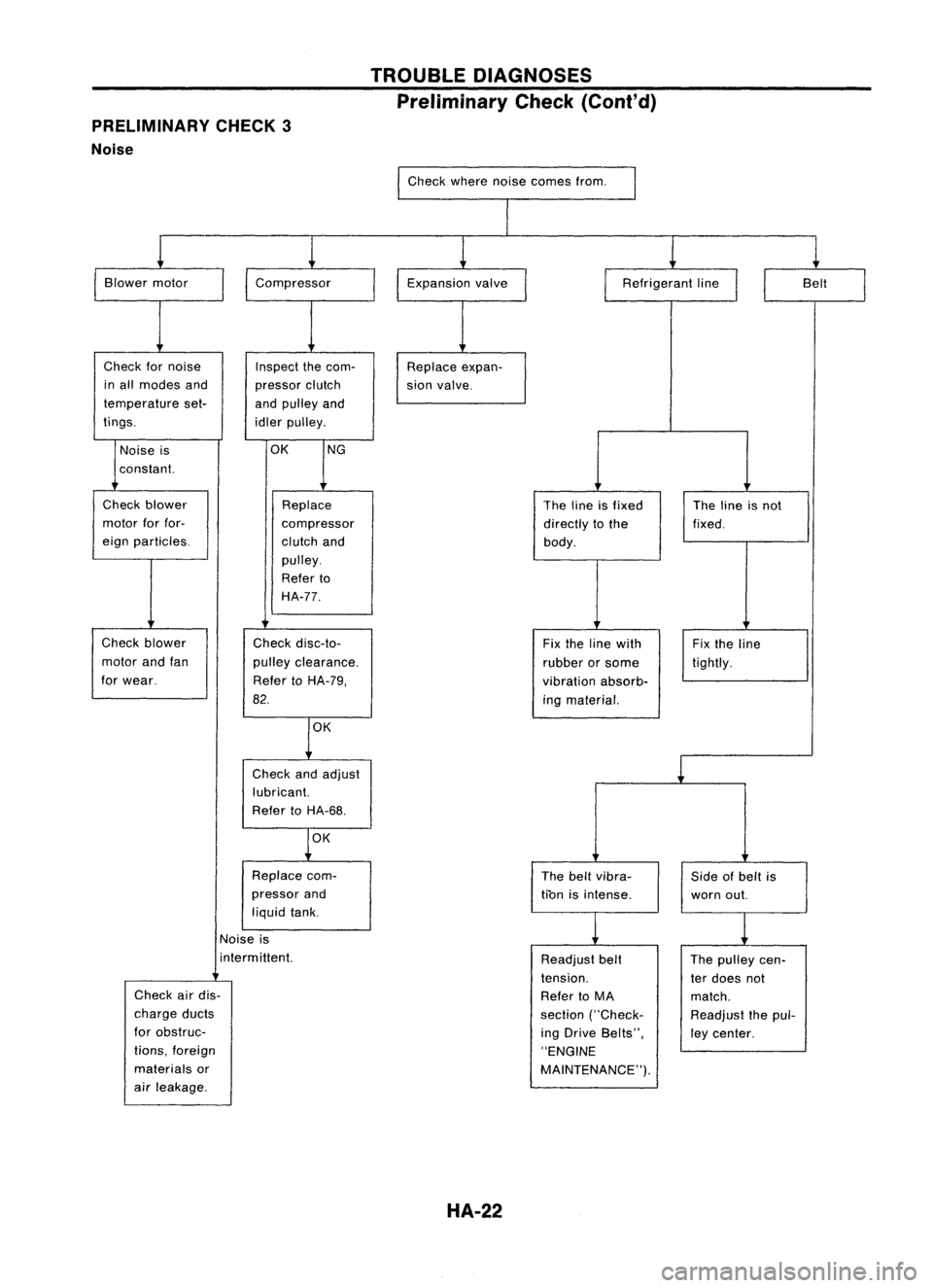
PRELIMINARY CHECK3
Noise TROUBLE
DIAGNOSES
Preliminary Check(Coni'd)
Check wherenoisecomes from.
I
I
Blower motor
Check fornoise
in all modes and
temperature set-
tings.
I
Compressor
Inspect thecom-
pressor clutch
and pulley and
idler pulley. Expansion
valve
Replace expan-
sion valve.
I
Refrigerant line
II
Belt
I
Noise is
constant.
OK
NG
Check blower
motor forfor-
eign particles.
Check blower
motor andfan
for wear. Replace
compressor
clutch and
pulley.
Refer to
HA-77.
Check disc-to-
pulley clearance.
Refer toHA-79,
82.
OK
Check andadjust
lubricant.
Refer toHA-68.
OK
Replace com-
pressor and
liquid tank. The
lineisfixed
directly tothe
body.
Fix the line with
rubber orsome
vibration absorb-
ing material.
The beltvibra-
tion isintense. The
lineisnot
fixed.
Fix the line
tightly.
Side ofbelt is
worn out.
Noise is
i nterm ittent.
Check airdis-
charge ducts
for obstruc-
tions, foreign
materials or
air leakage.
HA-22
Readjust
belt
tension.
Refer toMA
section ("Check-
ing Drive Belts",
"ENGINE
MAINTENANCE"). The
pulley cen-
ter does not
match.
Readjust thepul-
ley center.
Page 1454 of 1701
TROUBLEDIAGNOSES
RHA351F @
(Go tonext page.)
Note:
If the result isNG after checking circuitcontinuity, repairharness orconnec-
tor.
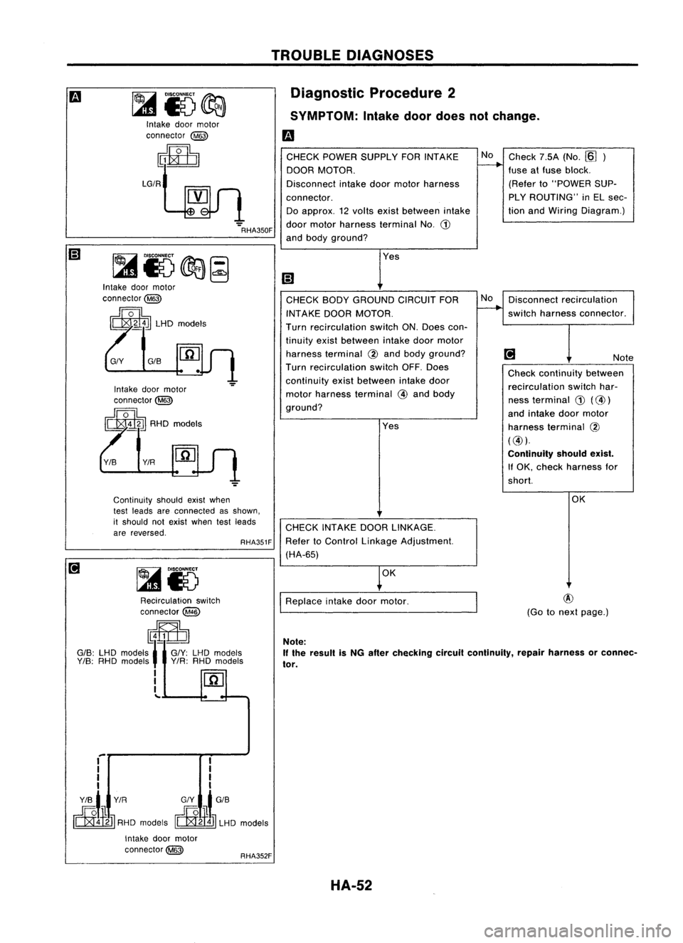
Diagnostic
Procedure2
SYMPTOM: Intakedoordoes notchange.
m
CHECK POWER SUPPLY FORINTAKE No
Check 7.5A(No.~)
DOOR MOTOR.
f-----.-
fuseatfuse block.
Disconnect intakedoormotor harness (Refer
to"POWER SUP-
connector. PLY
ROUTING" inEL sec-
Do approx. 12volts exist between intake tion
and Wiring Diagram.)
door motor harness terminal No.
G)
and body ground?
Yes
(;J
CHECK BODYGROUND CIRCUITFORNo
Disconnect recirculation
INT AKE DOOR MOTOR.
~
switch harness connector.
Turn recirculation switchON.Does con-
tinuity existbetween intakedoormotor
harness terminal
@
and body ground?
@J
Note
Turn recirculation switchOFF.Does
Checkcontinuity between
continuity existbetween intakedoor
recirculationswitchhar-
motor harness terminal
@
and body
nessterminal
G)
(@)
ground? andintake doormotor
Yes harnessterminal @
(@).
Continuity shouldexist.
If OK, check harness for
short.
OK
CHECK INTAKE DOORLINKAGE.
Refer toControl Linkage Adjustment.
(HA-65)
OK
I
Replace intakedoormotor.
GIS
Intake
doormotor
connector @
~
LGIRt
~JJ
1
RHA350F
Continuity shouldexistwhen
test leads areconnected asshown,
it should notexist when testleads
are reversed.
~i5@a~
Intake doormotor
connector@
~ LHDmodels
~15 Recirculation switch
connector@
~
GIS: LHOmodels
1-
GIY: LHOmodels
Y/S:
RHO mOdels' VIR:RHO models
I
I
I
'"
RHA352F
.-
I
I
I
Y/S
t
Y/R G/Y
t
GIS
rERl-¥1Jl
RHDmodels ~ LHOmodels
Intake doormotor
connector@
HA-52
Page 1466 of 1701
TROUBLEDIAGNOSES
Electrical Components Inspection(Cont'd)
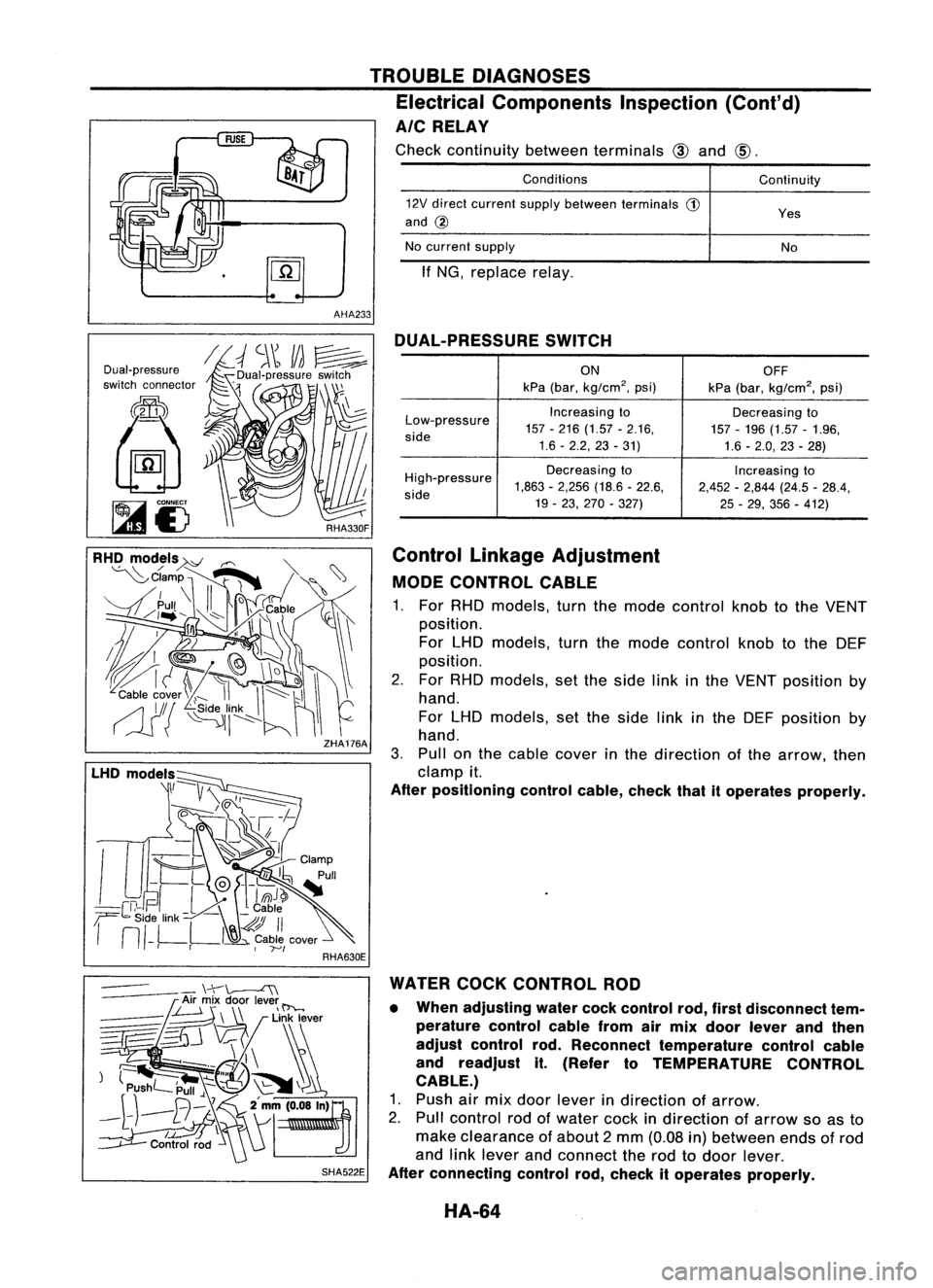
AIC RELAY
Check continuity betweenterminals
CID.
AHA233
Conditions
12V direct current supplybetween terminals
G)
and
@
No current supply
If NG, replace relay. Continuity
YesNo
Dual-pressure
switch connector
SHA522EDUAL-PRESSURE
SWITCH
ON OFF
kPa (bar,
kg/cm
2,
psi)
kPa(bar,
kg/cm
2,
psi)
Low-pressure Increasing
to
Decreasingto
157 -216 (1.57 -2.16,
157-196 (1.57-1.96,
side
1.6-2.2,23 -31)
1.6-2.0,23 -28)
High-pressure Decreasing
to
Increasingto
1,863 -2,256 (18.6-22.6,
2,452-2,844 (24.5-28.4,
side
19-23, 270 -327)
25-29, 356 -412)
Control Linkage Adjustment
MODE CONTROL CABLE
1. For RHO models, turnthemode control knobtothe VENT
position.
For LHO models, turnthemode control knobtothe OEF
position.
2. For RHO models, setthe side linkinthe VENT position by
hand.
For LHO models, setthe side linkinthe OEF position by
hand.
3. Pullan thecable cover inthe direction ofthe arrow, then
clamp it.
After positioning controlcable,checkthatitoperates properly.
WATER COCKCONTROL ROD
• When adjusting watercockcontrol rod,firstdisconnect tem-
perature controlcablefromairmix door lever andthen
adjust control rod.Reconnect temperature controlcable
and readjust it.(Refer toTEMPERATURE CONTROL
CABLE.)
1. Push airmix door lever indirection ofarrow.
2. Pull control rodofwater cockindirection ofarrow soasto
make clearance ofabout 2mm (0.08 in)between endsofrod
and linklever andconnect therod todoor lever.
After connecting controlrod,check itoperates properly.
HA-64
Page 1478 of 1701

SR20DEenginemodels
SEC.
274.275
~ :N.m (kg-m, ft-Ib)
SERVICE
PROCEDURES
Compressor Mounting(Cont'd)
~ 16•19 (1.6 •1.9, 12•14)
~ 45-60 (4.6 -6.1, 33•44)
~45.60 (4.6-6.1, 33•44)
Belt Tension
• Refer toMA section.
Fast IdleControl Device(FICO)
• Refer toEC section.
HA-76 AHA387
Page 1491 of 1701
PRE-DELIVERYINSPECTIONITEMS
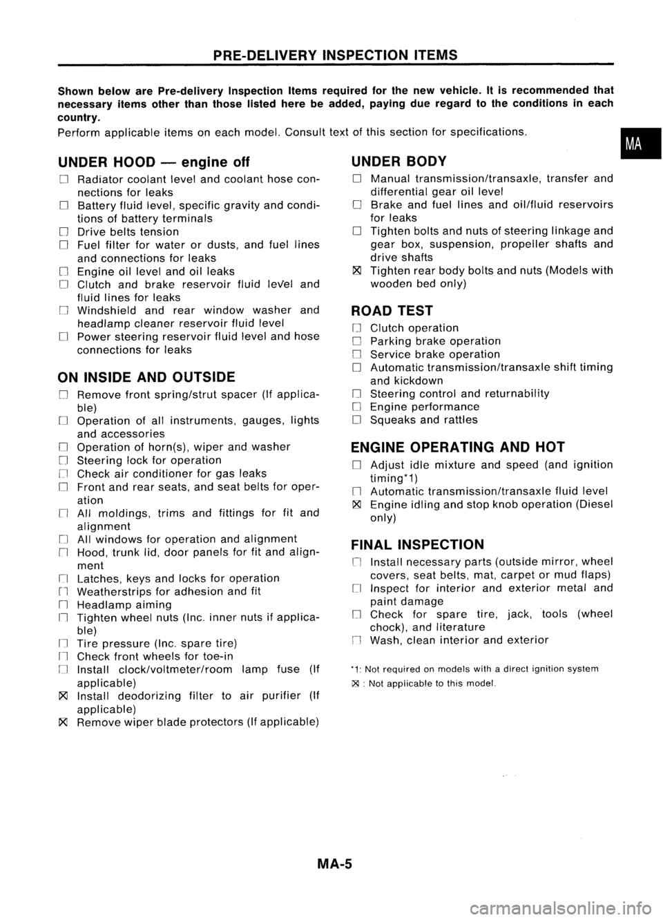
Shown belowarePre-delivery InspectionItemsrequired forthe new vehicle. Itis recommended that
necessary itemsotherthanthose listedherebeadded, payingdueregard tothe conditions ineach
country.
Perform applicable itemsoneach model. Consult textofthis section forspecifications .
UNDER HOOD-engine off
o
Radiator coolantlevelandcoolant hosecon-
nections forleaks
o
Battery fluidlevel, specific gravityandcondi-
tions ofbattery terminals
o
Drive beltstension
D
Fuel filter forwater ordusts, andfuel lines
and connections forleaks
[] Engine oillevel andoilleaks
D
Clutch andbrake reservoir fluidlevel and
fluid lines forleaks
o
Windshield andrear window washerand
headlamp cleanerreservoir fluidlevel
D
Power steering reservoir fluidlevel andhose
connections forleaks
ON INSIDE ANDOUTSIDE
D
Remove frontspring/strut spacer(Ifapplica-
ble)
D
Operation ofall instruments, gauges,lights
and accessories
o
Operation ofhorn(s), wiperandwasher
[] Steering lockforoperation
[] Check airconditioner forgas leaks
o
Front andrear seats, andseat belts foroper-
ation
n
All moldings, trimsandfittings forfitand
alignment
[J
Allwindows foroperation andalignment
n
Hood, trunklid,door panels forfitand align-
ment
[1
Latches, keysandlocks foroperation
rl
Weatherstrips foradhesion andfit
[l
Headlamp aiming
I~ Tighten wheelnuts(Inc. inner nutsifapplica-
ble)
IJ Tire pressure (Inc.spare tire)
Il
Check frontwheels fortoe-in
IJ Install clock/voltmeter/room lampfuse(If
applicable)
~ Install deodorizing filtertoair purifier (If
applicable)
~ Remove wiperbladeprotectors (Ifapplicable)
UNDER
BODY
o
Manual transmission/transaxle, transferand
differential gearoillevel
D
Brake andfuel lines andoil/fluid reservoirs
for leaks
D
Tighten boltsandnuts ofsteering linkageand
gear box,suspension, propellershaftsand
drive shafts
~ Tighten rearbody boltsandnuts (Models with
wooden bedonly)
ROAD TEST
D
Clutch operation
D
Parking brakeoperation
[J
Service brakeoperation
D
Automatic transmission/transaxle shifttiming
and kickdown
[] Steering controlandreturnability
o
Engine performance
D
Squeaks andrattles
ENGINE OPERATING ANDHOT
D
Adjust idlemixture andspeed (andignition
timing*1)
n
Automatic transmission/transaxle fluidlevel
~ Engine idlingandstop knob operation (Diesel
only)
FINAL INSPECTION
n
Install necessary parts(outside mirror,wheel
covers, seatbelts, mat,carpet ormud flaps)
[1
Inspect forinterior andexterior metaland
paint damage
[] Check forspare tire,jack, tools (wheel
chock), andliterature
n
Wash, cleaninterior andexterior
"1: Not required onmodels withadirect ignition system
~ :Not appiicable tothis model.
•
MA-5