Page 1655 of 1701
TROUBLEDIAGNOSES -Supplemental RestraintSystem(SRS)-
Dual AirBag System
Self-diagnosis (Cont'd)
No.
ON
OFF
IGN
ON
t
"AIR
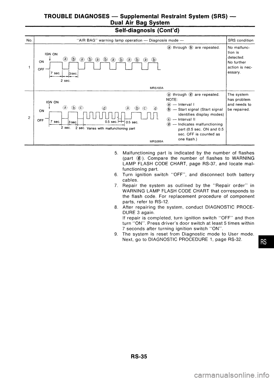
BAG" warning lampoperation -Diagnosis mode-
@
through
@
are repeated.
MRS100A
SRS
condition
No malfunc-
tion is
detected. No further
action isnec-
essary.
2 ON
OFF
IGN
ON
I
7 sec.
@)
@
(c)
3sec.
2 sec. 2sec. Varies withmalfunctioning part
MRS099A
@
through
@
are repeated.
NOTE: @ -
Interval I
@ -
Start signal (Startsignal
identifies displaymodes)
@ -
Interval II
@ -
Indicates malfunctioning
part (0.5sec. ONand 0.5
sec. OFF iscounted as
one flash.) The
system
has problem
and needs to
be repaired.
5. Malfunctioning partisindicated bythe number offlashes
(part
@).
Compare thenumber offlashes toWARNING
LAMP FLASH CODECHART, pageRS-37, andlocate mal-
functioning part.
6. Turn ignition switch"OFF", anddisconnect bothbattery
cables.
7. Repair thesystem asoutlined bythe "Repair order"in
WARNING LAMPFLASH CODECHART thatcorresponds to
the flash code. Forreplacement procedureofcomponent
parts, refertoRS-12.
8. After repairing thesystem, conduct DIAGNOSTIC PROCE-
DURE 3again.
If repair iscompleted, turnignition switch"OFF"andthen
turn "ON". Pressdriver's doorswitch atleast 5times within
7 seconds afterturning ignition switch"ON".
9. The system isreset fromDiagnostic modetoUser mode.
Next, gotoDIAGNOSTIC PROCEDURE 1,page RS-32. •
RS-35
Page 1659 of 1701
NoSRSisingood order. Set-
ting theCONSULT tothe
Diagnosis modeisimpos-
sible. Nofurther actionis
necessary.
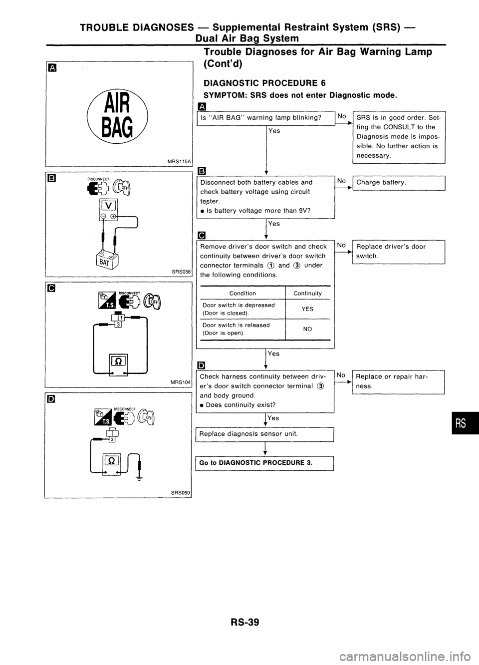
Is
"AIR BAG" warning lampblinking?
Yes
MRS115A
TROUBLE
DIAGNOSES -Supplemental RestraintSystem(SRS)-
Dual AirBag System
Trouble Diagnoses forAir Bag Warning Lamp
m
(Cont'd)
DIAGNOSTIC PROCEDURE 6
SYMPTOM: SRSdoes notenter Diagnostic mode.
m
NoCharge battery.
SRS058
Disconnect
bothbattery cablesand
check battery voltage usingcircuit
te.ster .
• Is battery voltage morethan9V?
Remove driver'sdoorswitch andcheck
continuity betweendriver'sdoorswitch
connector terminals
G)
and
@
under
the following conditions.
No
Replace driver'sdoor
switch.
Condition
Door switch isdepressed
(Door isclosed).
Door switch isreleased
(Door isopen). Continuity
YES
NO
MRS104
00
Check harness continuity betweendriv-
er's door switch connector terminal
@
and body ground .
• Does continuity exist?
Yes
Replace diagnosis sensorunit.
I
Go 10DIAGNOSTIC PROCEDURE3.No
Replace orrepair har-
ness.
•
SRS060
RS-39
Page 1663 of 1701
TROUBLEDIAGNOSES -Supplemental RestraintSystem(SRS)-
Single AirBag System
Self-diagnosis
DIAGNOSTIC PROCEDURE 7
(@
without CONSULT)
Checking SRSoperation byusing "AIRBAG" warning lamp-
User mode
1. After turning ignition switchfrom"OFF" to"ON", "AIR
BAG" warning lampoperates.
2. Compare "AIRBAG" warning lampoperation tothe chart
below.
Note: CONSULT cannotbeused fortrouble diagnoses.
"AIR BAG" warning lampoperation -User mode
1. Normal
IGNON
ON
!--
OFF J Approx.I _
I}
sec...
I
2. Abnormal -Ifthe warning lampshows asfollows, checktheSRS immediately.
e Blinking
e Warning lampdoes notilluminate atall.
ON
OFF
ON
OFF o.5~sec.
IGN ON
,----,
I I
I I
I
I
•
ecootiooo::JOO_IG_N_O_N _
OFF MRS106
RS-43
Page 1684 of 1701
MANUALSTEERING GEARANDLINKAGE (ModelR24N)
Assembly andAdjustment
(Cont'd)
4. Measure rackstroke.
Measure stroke
"S":
Refer toSOS (ST-35).
AST141
5.Before installing boot,coatthecontact surfaces between
boot andtie-rod withgrease.
~==--
SST967A
6.Install bootclamps.
• Toinstall, wrapbootclamp around bootgroove twice.Use
a screwdriver totighten clamps. Twistringsatboth ends 4
to 4-1/2 turns while pulling themwithaforce ofapprox. 98
N (10 kg,22lb).
• Donot cross wireonboot.
AST137
•Bend twisted endofboot clamp asshown atleft. (This will
prevent interference withother parts.)
AST138
ST-18
Page 1686 of 1701
POWERSTEERING GEARANDLINKAGE (ModelPR24AC)
Removal andInstallation (Cont'd)
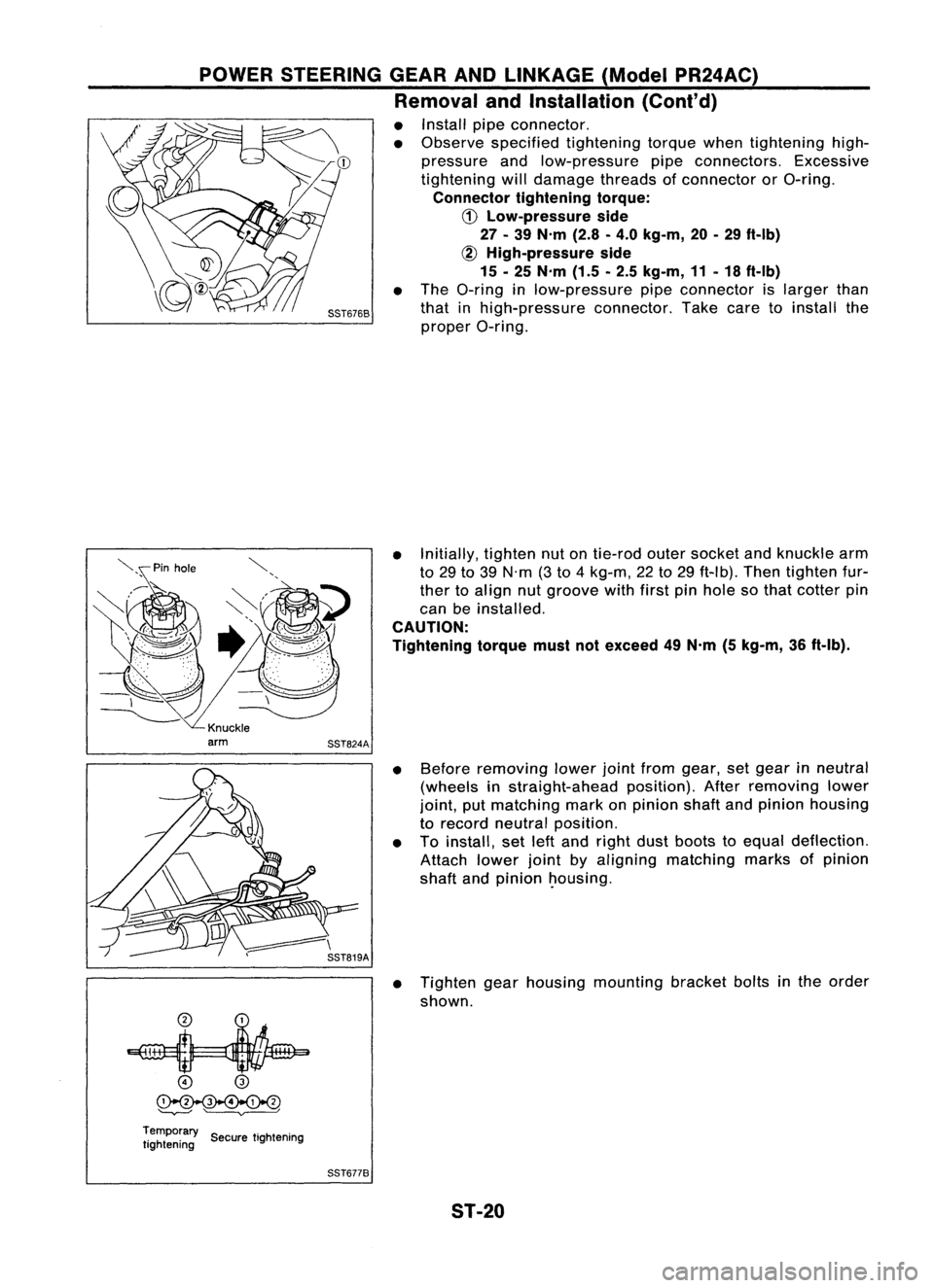
• Install pipeconnector.
• Observe specified tightening torquewhentightening high-
pressure andlow-pressure pipeconnectors. Excessive
tightening willdamage threadsofconnector orO-ring.
Connector tighteningtorque:
CD
Low-pressure side
27 -39 N'm (2.8-4.0 kg-m, 20-29 ft-Ib)
~ High-pressure side
15 -25 N'm (1.5-2.5 kg-m, 11-18 ft-Ib)
• The O-ring inlow-pressure pipeconnector islarger than
that inhigh-pressure connector.Takecaretoinstall the
proper O-ring.
• Initially, tightennutontie-rod outersocket andknuckle arm
to 29 to39 N'm (3to 4kg-m, 22to29 ft-Ib). Thentighten fur-
ther toalign nutgroove withfirstpinhole sothat cotter pin
can beinstalled.
CAUTION:
Tightening torquemustnotexceed 49N'm (5kg-m, 36ft-Ib).
• Before removing lowerjointfrom gear, setgear inneutral
(wheels instraight-ahead position).Afterremoving lower
joint, putmatching markonpinion shaftandpinion housing
to record neutral position.
• Toinstall, setleftand right dustboots toequal deflection.
Attach lowerjointbyaligning matching marksofpinion
shaft andpinion ~ousing.
• Tighten gearhousing mounting bracketboltsinthe order
shown.
o
@
~
'--v---' ~
Temporary ..
tightening SecuretIghtening
SST6778
ST-20
Page 1688 of 1701
POWERSTEERING GEARANDLINKAGE (ModelPR24AC)
Disassembly
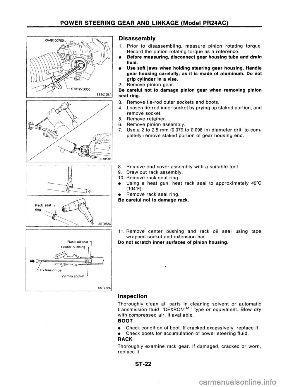
1. Prior todisassembling, measurepinionrotating torque.
Record thepinion rotating torqueasareference.
• Before measuring, disconnectgearhousing tubeanddrain
fluid.
• Use softjaws when holding steering gearhousing. Handle
gear housing carefully, asitis made ofaluminum. Donot
grip cylinder inavise.
2. Remove piniongear.
Be careful nottodamage piniongearwhen removing pinion
seal ring.
3. Remove tie-rodoutersockets andboots.
4. Loosen tie-rodinnersocket byprying upstaked portion, and
remove socket.
5. Remove retainer.
6. Remove pinionassembly.
7. Use a2to 2.5 mm (0.079 to0.098 in)diameter drilltocom-
pletely remove stakedportion ofgear housing end.
8. Remove endcover assembly withasuitable tool.
9. Draw outrack assembly.
10. Remove rackseal ring.
• Using aheat gun,heat racksealtoapproximately 40°C
(104°F).
• Remove racksealring.
Be careful nottodamage rack.
11. Remove centerbushing andrack oilseal using tape
wrapped socketandextension bar.
Do not scratch innersurfaces ofpinion housing .
.. !tension bar
29 mm socket
SST472AInspection
Thoroughly cleanallparts incleaning solventorautomatic
transmission fluid''DEXRON™,, typeorequivalent. Blowdry
with compressed air,ifavailable.
BOOT
• Check condition ofboot. Ifcracked excessively, replaceit.
• Check bootsforaccumulation ofpower steering fluid.
RACK
Thoroughly examinerackgear. Ifdamaged, crackedorworn,
replace it.
ST-22
Page 1692 of 1701
POWERSTEERING GEARANDLINKAGE (ModelPR24AC)
Assembly (Cont'd)
14. Ensure thattherack iscentered. Installrearcover capso
that itsprotrusion ispositioned asshown infigure.
Be careful nottodamage wormringandoilseal.
88T507C
15.Install diaphragm springintogear housing.
• Always installretainer, springwasher anddiaphragm
spring inthat order.
• Make sureconvex end(painted white)ofdiaphragm spring
faces outward wheninstalling.
16. Install retainer springandadjusting screwtemporarily.
88T0878
17.Install newlockplate.
a. Attach lockplate
@
toside rodinner socket
(!).
b. Insert steering gearspacer
CID
torack
@.
c. Apply locking sealant toinner socket threads
CID.
Screw innersocket intorack
@
and tighten tospecified
torque.
d. Stake lockplate attwo places.
CAUTION:
To prevent scratching theboot, remove burrsfromlockplate.
18. Tighten outersocket locknut.
Tie-rod length
"L":
Refer toSOS (ST-35).
88T0938
19.Measure rackstroke.
Rack stroke
"5":
Refer to50S (ST-35).
s
88T0868A ST-26
Page 1693 of 1701
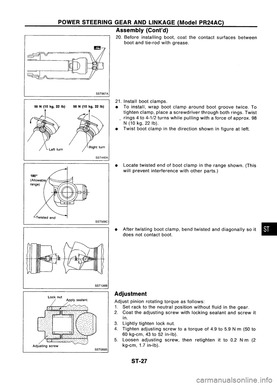
POWERSTEERING GEARANDLINKAGE (ModelPR24AC)
Assembly (Cont'd)
20. Before installing boot,coatthecontact surfaces between
boot andtie-rod withgrease.
88T967A
21.Install bootclamps.
• Toinstall, wrapbootclamp around bootgroove twice.To
tighten clamp,placeascrewdriver throughbothrings. Twist
rings 4to 4-1/2 turns while pulling withaforce ofapprox. 98
N (10 kg,22Ib).
• Twist bootclamp inthe direction showninfigure atleft.
88T440A
•Locate twisted endofboot clamp inthe range shown. (This
will prevent interference withother parts.)
88TS09C
88T1268
•
After twisting bootclamp, bendtwisted anddiagonally soit •
does notcontact boot.
Adjusting screw
88T0898Adjustment
Adjust pinionrotating torqueasfollows:
1. Set rack tothe neutral position withoutfluidinthe gear.
2. Coat theadjusting screwwithlocking sealant andscrew it
in.
3. Lightly tighten locknut.
4. Tighten adjusting screwtoatorque of4.9 to5.9 N'm (50to
60 kg-em, 43to52 in-Ib).
5. Loosen adjusting screw,thenretighten itto 0.2 N'm (2
kg-em, 1.7in-Ib).
ST-27