1995 NISSAN ALMERA N15 ECO mode
[x] Cancel search: ECO modePage 1513 of 1701
ENGINEMAINTENANCE
SEF051PA SEF909P
*
NO FAIL
0
~y~r
GrJ-~
Data linkconnector forCONSULT
(Connect CHKandIGN terminals
with asuitable harness.)
•
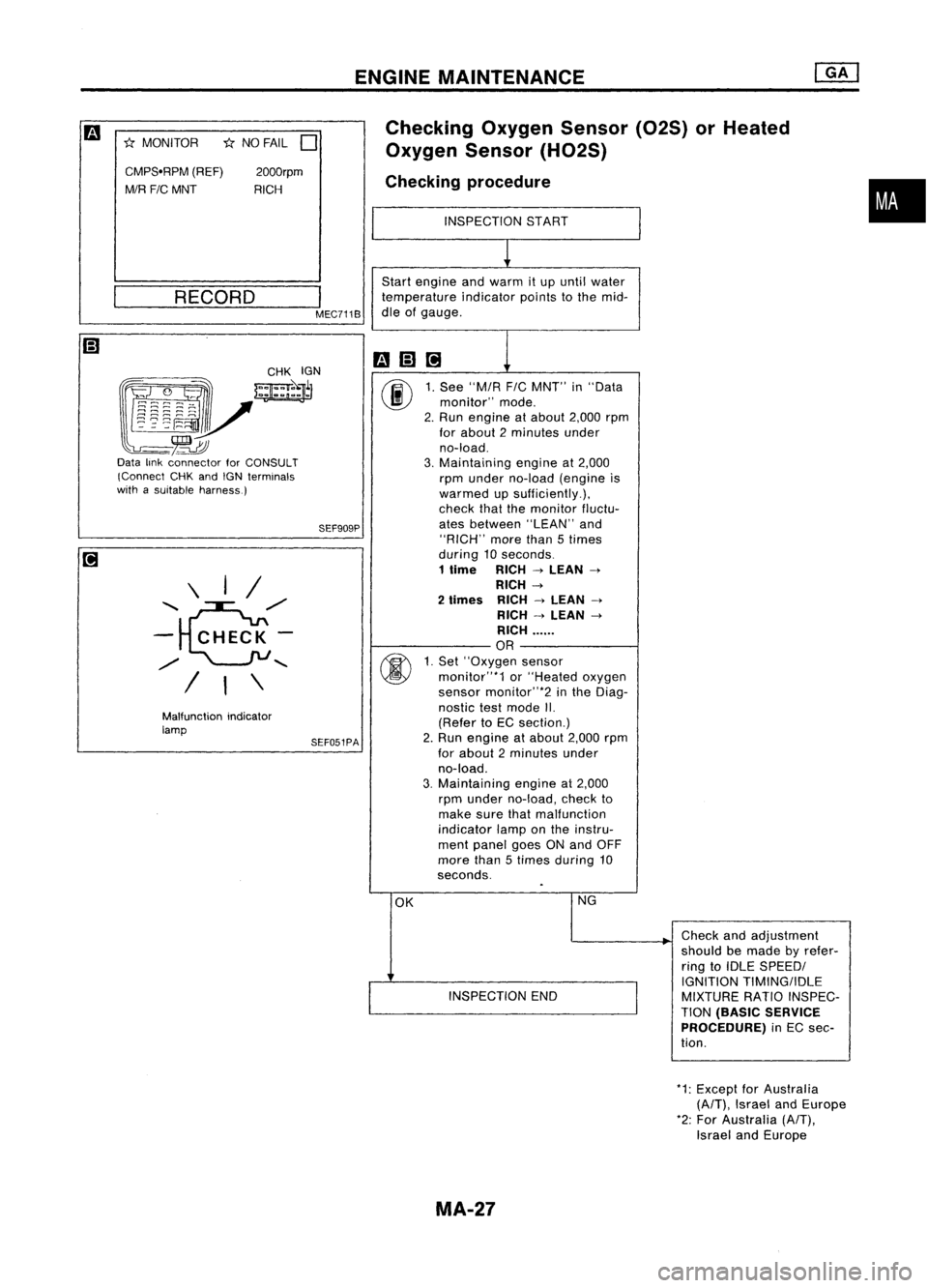
Checking
OxygenSensor(02S)orHeated
Oxygen Sensor(H02S)
Checking procedure
INSPECTION START
~
Start engine andwarm itup until water
temperature indicatorpointstothe mid-
dle ofgauge.
mm@]
1
00
1.
See "MIA
FIC
MNT" in"Data
monitor" mode.
2. Run engine atabout 2,000rpm
for about 2minutes under
no-load.
3. Maintaining engineat2,000
rpm under no-load (engine is
warmed upsufficiently.),
check thatthemonitor fluctu-
ates between "LEAN"and
"RICH" morethan5times
during 10seconds.
1
lime
RICH
->
LEAN
->
RICH
->
2
limes
RICH
->
LEAN
->
RICH
->
LEAN
->
RICH ......
OR
00
1.
Set' 'Oxygen sensor
monitor"*1 or"Heated oxygen
sensor monitor"*2 inthe Diag-
nostic testmode II.
(Refer toEC section.)
2. Run engine atabout 2,000rpm
for about 2minutes under
no-load.
3. Maintaining engineat2,000
rpm under no-load, checkto
make surethatmalfunction
indicator lamponthe instru-
ment panel goesONand OFF
more than5times during 10
seconds.
OK NG
Checkandadjustment
should bemade byrefer-
ring toIDLE SPEEDI
I
IGNITION
TIMINGIIDLE
INSPECTION END
MIXTURERATIOINSPEC-
TION
(BASIC SERVICE
PROCEDURE)
inEC sec-
tion.
I
MEC711B
2000rpm
RICH
RECORD
Malfunction indicator
lamp \
I/
'e/'
-
CHECK-
/
"
/ I\
CMPS'RPM
(REF)
MIR FIC
MNT
*
MONITOR
*1:Except forAustralia
(A/T),
Israel andEurope
*2: For Australia
(A/T),
Israel andEurope
MA-27
Page 1518 of 1701
![NISSAN ALMERA N15 1995 Service Manual ENGINEMAINTENANCE [][]
Checking CoolingSystem(Cont'd)
Pull thenegative-pressure valvetoopen it.Check thatitcloses
completely whenreleased.
CHECKING COOLINGSYSTEMFORLEAKS
Apply pressure tothe c NISSAN ALMERA N15 1995 Service Manual ENGINEMAINTENANCE [][]
Checking CoolingSystem(Cont'd)
Pull thenegative-pressure valvetoopen it.Check thatitcloses
completely whenreleased.
CHECKING COOLINGSYSTEMFORLEAKS
Apply pressure tothe c](/manual-img/5/57349/w960_57349-1517.png)
ENGINEMAINTENANCE [][]
Checking CoolingSystem(Cont'd)
Pull thenegative-pressure valvetoopen it.Check thatitcloses
completely whenreleased.
CHECKING COOLINGSYSTEMFORLEAKS
Apply pressure tothe cooling systemwithcaptester tocheck
f~r leakage.
Testing pressure:
157 kPa (1.57 bar,1.6kg/cm
2,
23psi)
CAUTION:
Higher pressure thanthespecified valuemaycause damage to
radiator.
SMA811C
SMA803A
Checking
FuelLines
Inspect fuellines andtank forimproper attachment, leaks,
cracks, damage, looseconnections, chafingordeterioration.
If necessary, repairorreplace faultyparts.
3 (0.12) Unit:mm(in)
_._-- --,"'~'r---1
"
,
-
-
---;--,
-,---
•• J..
_J- __
28 (1.10)
~ Fuel hose clamps
1.0 -1.5 N.m
(0.10 -0.15 kg-m,
8.7 -13.0 in-Ib)
MMA104A
• FUEL PRESRELEASE.
0
FUEL PUMP WILLSTOP BY
TOUCHING STARTDURING
IDLE_
CRANK AFEW TIMES AFTER
ENGINE STALL.
---S-T~-RT--
SEF823KCAUTION:
Tighten high-pressure rubberhoseclamp sothat clamp endis
3 mm (0.12 in)from hose end.
Tightening torquespecifications arethesame forallrubber
hose clamps.
Ensure thatscrew doesnotcontact adjacent parts.
Changing FuelFilter
WARNING:
Before removing fuelfilter, release fuelpressure fromfuelline
to eliminate danger.
rF.i\
1.Start engine.
~ 2.Perform "FUELPRESSURE RELEASE"in"WORK
SUPPORT" modewithCONSULT.
3. After engine stalls,crankengine twoorthree times
to make surethatfuel pressure isreleased.
4. Turn ignition switchoff.
MA-32
Page 1523 of 1701
ENGINEMAINTENANCE
SEF051PA SEF909P
*
NO FAIL
D
Malfunction indicator
lamp
•
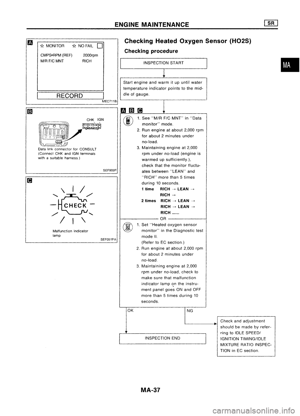
Checking
HeatedOxygen Sensor(H02S)
Checking procedure
INSPECTION START
1
Start engine andwarm itup until water
temperature indicatorpointstothe mid-
dle ofgauge.
m(;]ri
1
00
1.
See "M/R F/CMNT" in"Data
monitor" mode.
2. Run engine atabout 2,000rpm
for about 2minutes under
no-load.
3. Maintaining engineat2,000
rpm under no-load (engine is
warmed upsufficiently.),
check thatthemonitor fluctu-
ates between "LEAN"and
"RICH" morethan5times
during 10seconds.
1 time RICH
-4
LEAN
-4
RICH
-4
2
times RICH
-4
LEAN
-4
RICH
-4
LEAN
-4
RICH ......
OR
@
1.
Set "Heated oxygensensor
monitor" inthe Diagnostic test
mode II.
(Refer toEC section)
2. Run engine atabout 2,000rpm
for about 2minutes under
no-load.
3. Maintaining
engineat2,000
rpm under no-load, checkto
make surethatmalfunction
indicator lamp~nthe instru-
ment panel goesONand OFF
more than5times during 10
seconds.
OK NG
.
Check
andadjustment
should bemade byrefer-
ring toIDLE SPEEDI
INSPECTION END
IGNITIONTIMING/IDLE
MIXTURE RATIOINSPEC-
TION inEC section
2000rpm
RICH
\ I/
........ e./
- CHECK-
./
........
/ I\
CMPS.RPM
(REF)
M/R FICMNT
*
MONITOR
__ R_E_C_O_R_D __
I
MEC711B
~~~~:?~;~
~~r
l~~~~V
-~~
Data linkconnector forCONSULT
(Connect CHKandIGN terminals
with asuitable harness.)
MA-37
Page 1532 of 1701
CHASSISANDBODY MAINTENANCE
Changing
MIT
Oil
1. Drain oilfrom drain plugandrefill withnewgear oil.
2. Check oillevel. (Refer to"Checking
M/T
Oil".)
Oil grade:
API GL-4
Viscosity: See "RECOMMENDED FLUIDSANDLUBRICANTS",
MA-14.
Capacity: RS5F30A 2.8-3.0f
(4-7/8 -5-114
Imppi)
RS5F31A 2.9-3.2£
(5-1/8 -5-518
Imppt)
RS5F32A 3.7-3.9£ (6-112 -
6-7/8
Imppt)
Drain plug:
(OJ:
15-20 N'm (1.5-2.0 kg-m, 11-14 ft-Ib)
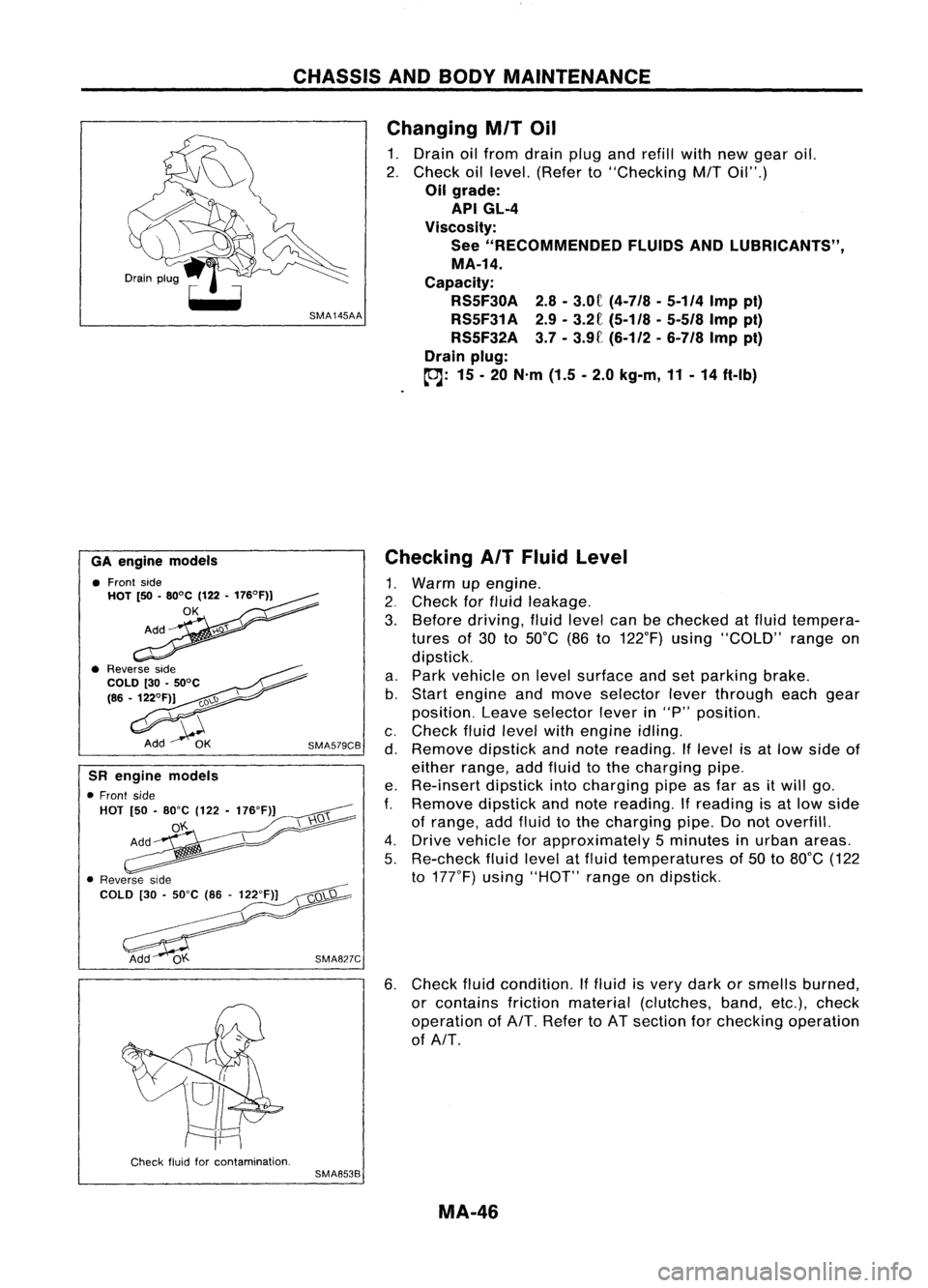
6. Check fluidcondition. Iffluid isvery dark orsmells burned,
or contains frictionmaterial (clutches, band,etc.),check
operation ofAlT. Refer toAT section forchecking operation
of AlT.
Checking
AIT
Fluid Level
1. Warm upengine .
2. Check forfluid leakage.
3. Before driving, fluidlevel canbechecked atfluid tempera-
tures of30 to50°C (86to122°F) using"COLD" rangeon
dipstick.
a. Park vehicle onlevel surface andsetparking brake.
b. Start engine andmove selector leverthrough eachgear
position. Leaveselector leverin"P" position.
c. Check fluidlevel withengine idling.
d. Remove dipstickandnote reading. Iflevel isat low side of
either range, addfluid tothe charging pipe.
e. Re-insert dipstickintocharging pipeasfar asitwill go.
f.
Remove dipstickandnote reading.
If
reading isat low side
of range, addfluid tothe charging pipe.Donot overfill.
4. Drive vehicle forapproximately 5minutes inurban areas.
5. Re-check fluidlevel atfluid temperatures of50 to80°C (122
to 177°F) using"HOT" rangeondipstick.
SMA827C
SMA579CB
GA
engine models
• Front side
HOT [50•80°C (122•176°F))
OK
SR engine models
• Front side
HOT [50•80"C (122-176"F)]
o'f..
Check fluidforcontamination.
SMA853B
MA-46
Page 1617 of 1701
SRA696A
SRA697A
S
Control rod
Lateral link
~H";""I"
ITorsion
beam
SRA698AREAR
SUSPENSION
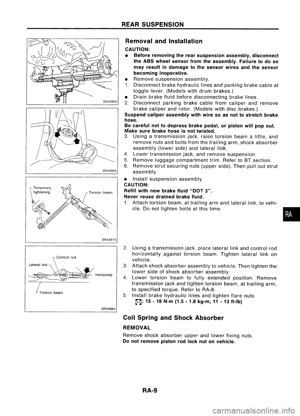
Removal andInstallation
CAUTION:
• Before removing therear suspension assembly,disconnect
the ABS wheel sensor fromtheassembly. Failuretodo so
may result indamage tothe sensor wiresandthesensor
becoming inoperative.
• Remove suspension assembly.
1. Disconnect brakehydraulic linesandparking brakecableat
toggle lever.(Models withdrum brakes.)
• Drain brake fluidbefore disconnecting brakelines.
2. Disconnect parkingbrakecablefromcaliper andremove
brake caliper androtor. (Models withdiscbrakes.)
Suspend caliperassembly withwire soasnot tostretch brake
hose.
Be careful nottodepress brakepedal, orpiston willpop out.
Make surebrake hoseisnot twisted.
3. Using atransmission jack,raise torsion beamalittle, and
remove nutsandbolts fromthetrailing arm,shock absorber
assembly (lowerside)andlateral link.
4. Lower transmission jack,andremove suspension.
5. Remove luggagecompartment trim.Refer toBT section.
6. Remove strutsecuring nuts(upper side).Thenpulloutstrut
assembly.
• Install suspension assembly.
CAUTION: Refill withnewbrake fluid"DOT
3".
Never reusedrained brakefluid.
1. Attach torsion beam,attrailing armandlateral link,tovehi-
cle. Donot tighten boltsatthis time.
2. Using atransmission jack,place lateral linkand control rod
horizontally againsttorsionbeam.Tighten laterallinkon
vehicle.
3. Attach shockabsorber assembly tovehicle. Thentighten the
lower sideofshock absorber assembly.
4. Lower torsion beamtofully extended position.Remove
transmission jackandtighten torsion beam,attrailing arm,
to specified torque.RefertoRA-8.
5. Install brakehydraulic linesandtighten flarenuts.
~: 15-18 N'm (1.5.1.8 kg-m,11-13 ft-Ib)
Coil Spring andShock Absorber
REMOVAL
Remove shockabsorber upperandlower fixing nuts.
Do not remove pistonrodlock nutonvehicle.
RA-9
•
Page 1638 of 1701
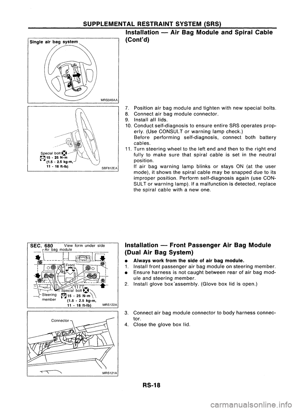
7.Position airbag module andtighten withnewspecial bolts.
8. Connect airbag module connector.
9. Install alllids.
10. Conduct self-diagnosis toensure entireSRSoperates prop-
erly. (Use CONSULT orwarning lampcheck.)
Before performing self-diagnosis, connectbothbattery
cables.
11. Turn steering wheeltothe leftend andthen tothe right end
fully tomake surethatspiral cableisset inthe neutral
position.
If air bag warning lampblinks orstays ON(atthe user
mode), itshows thespiral cablemaybesnapped duetoits
improper position.Performself-diagnosis again(useCON-
SUL Tor warning lamp).Ifa malfunction isdetected, replace
the spiral cablewithanew one.
SBF812EA
MRS046AA
SUPPLEMENTAL
RESTRAINTSYSTEM(SRS)
Installation -Air Bag Module andSpiral Cable
(Cont'd)
G\\
--------~
~\)
..~l~~
\\\?\\
Special bolt~~ "'(\\
cc:J
15-25 N.m ~
(1.5 -2.5 kg-m,
11 -18 ft-Ibl
Installation-Front Passenger AirBag Module
(Dual AirBag System)
• Always workfromtheside ofair bag module.
1. Install frontpassenger airbag module onsteering member.
• Ensure harness isnot caught between rearofair bag mod-
ule and steering member.
2. Install glovebox'assembly. (Gloveboxlidisopen.)
3. Connect airbag module connector tobody harness connec-
tor.
4. Close theglove boxlid.
RS-18
Page 1647 of 1701
TROUBLEDIAGNOSES -Supplemental RestraintSystem(SRS)
How toPerform TroubleDiagnoses forQuick
and Accurate Repair(Cont'd)
CAUTION:
• Donot use acircuit testertocheck SRSharness connectors unlessinstructed tointhis Service
Manual. Fordual airbag system, SRSwiring harnesses arecovered withyellow insulation either
just before theharness connectors orfor complete harness,foreasy identification.
• Donot attempt torepair, spliceormodify theSRS wiring harness. Ifthe harness isdamaged, replace
it with anew one.
• Keep ground portionclean.
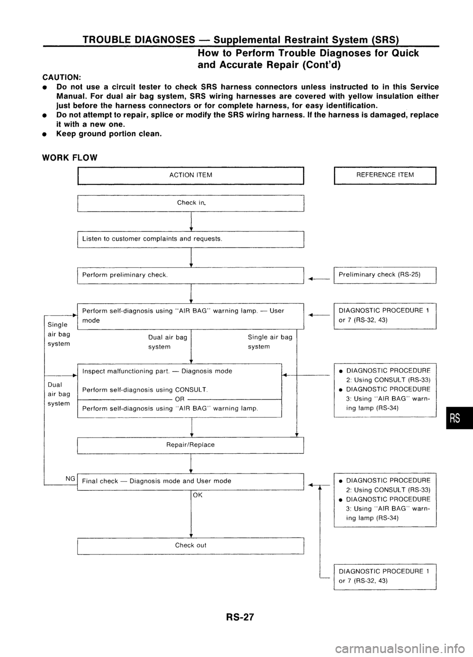
WORK FLOW
ACTIONITEM
Check in.
Listen tocustomer complaints andrequests.
Perform preliminary check. REFERENCE
ITEM
-+-1
Preliminary check(RS-25)
Perform self-diagnosis using"AIRBAG" warning lamp.-User
mode
Single
air bag
system Dual
airbag
system Single
airbag
system DIAGNOSTIC
PROCEDURE1
-+-
or7(RS-32, 43)
Dual
air bag
system Inspect
malfunctioning part.-Diagnosis mode
Perform self-diagnosis usingCONSULT.
OR
Perform self-diagnosis using"AIRBAG" warning lamp.
Repair/Replace •
DIAGNOSTIC PROCEDURE
2: Using CONSULT (RS-33)
• DIAGNOSTIC PROCEDURE
3: Using "AIRBAG" warn-
ing lamp (RS-34)
•
NG Final check -Diagnosis modeandUser mode
OK
Check out
RS-27 •
DIAGNOSTIC PROCEDURE
2: Using CONSULT (RS-33)
• DIAGNOSTIC PROCEDURE
3: Using "AIRBAG" warn-
ing lamp (RS-34)
DIAGNOSTIC PROCEDURE1
or 7(RS-32, 43)
Page 1654 of 1701
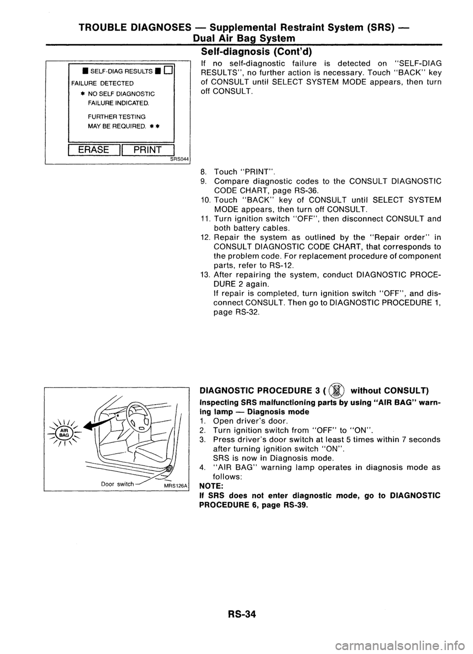
•SELF-DIAG RESULTS.
0
FAILURE DETECTED
• NO SELF DIAGNOSTIC
FAILURE INDICATED.
TROUBLE
DIAGNOSES -Supplemental RestraintSystem(SRS)-
Dual AirBag System
Self-diagnosis (Cont'd)
If no self-diagnostic failureisdetected on"SELF-DIAG
RESULTS", nofurther actionisnecessary. Touch"BACK" key
of CONSULT untilSELECT SYSTEM MODEappears, thenturn
off CONSULT.
FURTHER TESTING
MAY BEREQUIRED.
**
ERASE "PRINT
I
SRS044
8.Touch "PRINT".
9. Compare diagnostic codestothe CONSULT DIAGNOSTIC
CODE CHART, pageRS-36.
10. Touch "BACK" keyofCONSULT untilSELECT SYSTEM
MODE appears, thenturnoffCONSULT.
11. Turn ignition switch"OFF", thendisconnect CONSULTand
both battery cables.
12. Repair thesystem asoutlined bythe "Repair order"in
CONSULT DIAGNOSTIC CODECHART, thatcorresponds to
the problem code.Forreplacement procedureofcomponent
parts, refertoRS-12.
13. After repairing thesystem, conduct DIAGNOSTIC PROCE-
DURE 2again.
If repair iscompleted, turnignition switch"OFF", anddis-
connect CONSULT. ThengotoDIAGNOSTIC PROCEDURE 1,
page RS-32.
Door switch DIAGNOSTIC
PROCEDURE 3
(00
without CONSULT)
Inspecting SRSmalfunctioning partsbyusing "AIRBAG" warn-
ing lamp -Diagnosis mode
1. Open driver's door.
2. Turn ignition switchfrom"OFF" to"ON".
3. Press driver's doorswitch atleast 5times within 7seconds
after turning ignition switch"ON".
SRS isnow inDiagnosis mode.
4. "AIR BAG" warning lampoperates indiagnosis modeas
follows:
NOTE:
If
SRS does notenter diagnostic mode,gotoDIAGNOSTIC
PROCEDURE 6,page RS-39.
RS-34