Page 1079 of 1701
INSPECTIONEND
INSPECTION
START
CHECK OVERALL FUNCTION. OK
fiii\
1.Turn ignition switch"ON".
~ 2.Perform "PARK/NEUT POSI
SW CKT" in"FUNCTION
TEST" modewithCONSULT.
OR
rif1
1.Turn ignition switch"ON".
~ 2.Select "PINPOSI SW"in
"DATA MONITOR" modewith
CONSULT.
3. Check "PINPOSI SW"signal
under thefollowing conditions.
"N"
or
"P"
position: ON
Except aboveposition: OFF
OR
1. Make surethatinhibitor switch
circuit functions properly.
(Refer toAT section.)
2. Turn ignition switch"ON".
3. Check voltage between ECM
terminal @and ground under
the following conditions.
Voltage: UN" or
uP"
position
Approximately OV
Except aboveposition
Battery voltage
SEF963N
MEC7798
TROUBLE
DIAGNOSIS FORNON-DETECTABLE ITEMS
Park/Neutral PositionSwitch(Cont'd)
I
Inhibitor
switch(AIrmodels)
J
m
•PARKINEUT POSISWCKT •
SHIFT
OUT OFNIP-POSITION
THEN
TOUCH START
I
NEXT
II
START
I
MEC7318
m
*MONITOR *NO FAIL
0
PIN POSI SW ON
RECORD
m~i)~0
II
ECM
~CONNECTORII
30
NG
EC-360
Page 1083 of 1701

TROUBLEDIAGNOSIS FORNON-DETECTABLE ITEMS
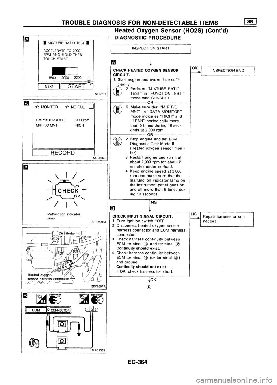
Heated Oxygen Sensor(H02S)(Cont'd)
DIAGNOSTIC PROCEDURE
• MIXTURE RATIOTEST.
ACCELERATE TO2000
RPM AND HOLD THEN
TOUCH START.
INSPECTION
START
*
NO FAIL
0
II=]
1800 20002200
ij
NEXT
II
START
J
RECORD \ I/
'~/'
- CHECK-
/
......
/ I\
INSPECTION
END
OK
NG
CHECK
HEATED OXYGEN SENSOR
CIRCUIT.
1. Start engine andwarm itup suffi-
ciently.
rF.i\
2.Perform "MIXTURE RATIO
\J!J
TEST"in"FUNCTION TEST"
mode withCONSULT.
OR
rF.i\
2.Make surethat"M/R FIC
\J!J
MNT"in"DATA MONITOR"
mode indicates "RICH"and
"LEAN" periodically more
than 5times during 10 sec-
onds at2,000 rpm.
OR
~ 2.Stop engine andsetECM
~ Diagnostic TestMode II
(Heated oxygensensormoni-
tor).
3. Restart engineandrunitat
about 2,000rpmforabout 2
minutes underno-load.
4. Keep engine speedat2,000
rpm andmake surethatthe
malfunction indicatorlampon
the instrument panelgoeson
and offmore than5times dur-
ing 10seconds.
SEF815L
I
MEC782B
2000rpm
RICH
CMPSoRPM
(REF)
M/R FICMNT
*.
MONITOR
Repairharness orcon-
nectors.
NG
OK
@
SEF089PA
Malfunction
indicator
lamp
~
Heated oxygen '~~
sensor harness connector \
ij
~I 1-''--\
CHECK
INPUTSIGNAL CIRCUIT.
SEF051PA
1.Turn ignition switch"OFF".
'-------------------' 2.Disconnect heatedoxygen sensor
harness connector andECM harness
connector.
3. Check harness continuity between
ECM terminal
@
and terminal
@.
Continuity shouldexist.
4. Check harness continuity between
ECM terminal
@
(orterminal
@)
and ground.
Continuity shouldnotexist.
if OK, check harness forshort.
II
~i5
ECM
-er
CONNECTOR
II
19
~i5
~
MEC735B EC-364
Page 1111 of 1701
TROUBLEDIAGNOSES
Quick-glow System(Cont'd)
EC-GLOW-01
IGNITION SWITCH IGNITIONSWITCH
START ONorSTART
7.5A
1261
10A
1251
10A
IT]
FUSE
BLOCK
(JIB)
@:ID
Refer
toEL-POWER.
:
LHDmodels
<£D:
RHOmodels
ECM
(ENGINECONTROL
MODULE)
@
TW
~
G/B
I
Toengine coolant
-------.. temperaturesensor
(Refer toEC-COOL/F.)
1I~11
Y
I
Y
I!i
COMBINATION
METER
(GLOW LAMP)
11
3•3
1
@
OR
I
OR
m
GIL
1Ni91
BR
BR
~
IGN
1Ni91
BR
BR
~
IGN
IN.41
B/Y
GNO-C GNO-C GNO-AGNO-A
12.6
I 11
3•9
I
11~11 11~51
B BB B
I
II I
----.-_-.- __1.
I
.-o-ee-°l
I
<;
A
;>
B
1---.1
B
-!-! .-!-
B/Y
~
START
Refertolast page
(Foldout page).
HEC088
EC-392
Page 1119 of 1701
TROUBLEDIAGNOSES ~
Partial LoadAdvance (PLA)Control (Cont'd)
LHD models
EC-PLA-01
~~~~K RefertoEL-POWER.
(JIB)
PLR REVGND-S GND-S
11~81 ~
/12.3
11
13.61
Y L!Y B/W B/W
I
I
f-
t
_I
t
Y ~ L!Y B!W
IrlsJ~ -
M.-B -
~I&~ ---
~r;]ID1
'T'
(E101)
L:jf'
"T'
Y L!Y B!W
1c!J~ ~
~cL~ ---
~c!J1
<=j=
(E231)
=r' =r'
Y L!Y B!W
!
L~Y B~Wt
rrh
m m
ECM
(ENGINECONTROL
MODULE)
@
TW
~
G!B
1
Toengine coolant
._--~. temperature sensor
(Refer toEC-COOL!F.)
II
N•4
1
B/Y
I
B/Y
Iffsn
START
IN;91
BR
I
BR
~
IGN
SOLENOID
TIMER ENGINE
SPEED
SENSOR INJECTION
PUMP
(E214)
~~
~ GY
~
(E214)
\ill)
GY
Refer
tolast page
(Foldout page).
HEC090
EC-400
Page 1133 of 1701
TROUBLEDIAGNOSES
Air Conditioner CutControl (Cont'd)
LHD models
EC-A/CCUT-01
Refer toEL-POWEA.
OFF
LG/R~
I
,
I
I
ON
A/C
LG/R
I
SWITCH
m
I
OFF
@
I
THERMO
CONTROL
AMP.
~
ON
L/Y
~ ~
G/B G/BG/Y
THERMISTOR
I I
m
._-~--_. rn
JUNCTION
BOX
NO.2
To compressor (JOINT
._ L/R. (Referto CONNECTORS)
I
HA-A/C.)~~
G/Y
00
~E~N~~gD
I?iJ
~~~TCH
VALVE OFF--~
IkjJ
(E64) ~
B (E65) B
I
r1
I
• .., BBB
1 ~
1
i....l
mm ~~
RIL
~
t
FUSE
BLOCK
(JIB)
~
(BOO)
R/L
IriDl
A/C
DUAL-
PRESSURE SWITCH
~
1~11I~211~1
LIB LG/R LG/R
II-~ --
LIB
L/Y
IT ~IA/C
n
RELAY
U
UID
4=JJ~
L L/R
~L
rn
I
ECM(ENGINECONTROLMODULE)
---------- @
n
LOW HIGH
... ~~_.
NORMAL
I!4Jl
G
~~1;1$1
G
m
COMP
~(E16)
T
L
JS4.ffi
(tiS)
B
~-----------.,
I I
:ITl~ ~~:
I I
L
~
IQl@
~ W
Refer
tolast page
(Foldout page).
CMID
(El0n
,
lf1@
(E106)
,
~
HEC095
EC-414
Page 1136 of 1701

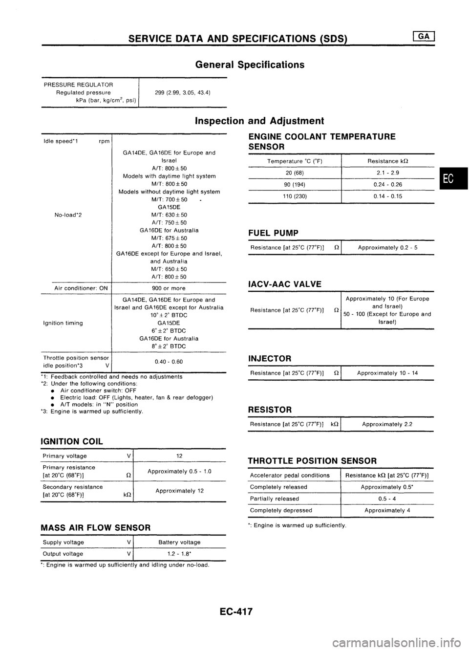
SERVICEDATAANDSPECIFICATIONS (SOS)
General Specifications
PRESSURE REGULATOR
Regulated pressure
kPa (bar, kg/cm
2,
psi) 299
(2.99, 3.05,43.4)
Idle speed'1
rpm
Inspection
andAdjustment
ENGINE COOLANT TEMPERATURE
SENSOR
Temperature
'c
('F) Resistancekn
20 (68) 2.1
-2.9
•
90
(194) 0.24-0.26
110 (230) 0.14-0.15
No-load'2
Air conditioner: ONGA
14DE, GA16DE forEurope and
Israel
AIT: 800:1:50
Models withdaytime lightsystem
MIT: 800:1:50
Models withoutdaytime lightsystem
M/T: 700:1:50
GA15DE
M/T: 630:1: 50
A/T: 750:1: 50
GA 16DE forAustralia
M/T: 675:1: 50
A/T: 800:1:50
GA16DE exceptforEurope andIsrael,
and Australia
M/T: 650:1:50
A/T: 800:1: 50
900 ormore
FUEL
PUMP
Resistance [at25'C (77'F)] n
IACV-AAC VALVE
Approximately
0.2-5
Ignition timing GA
14DE, GA16DE forEurope and
Israel andGA16DE except forAustralia
10':1:2' BTDC
GA15DE
6':1:2' BTDC
GA16DE forAustralia
8':1:2' BTDC Resistance
[at25'C (77'F)) Approximately
10(For Europe
n andIsrael)
50 -100 (Except forEurope and
Israel)
0.40. 0.60
Throttle
position sensor
idle position'3 V
'1: Feedback controlled andneeds noadjustments
'2: Under thefollowing conditions:
• Air conditioner switch:OFF
• Electric load:OFF(Lights, heater,fan
&
rear defogger)
• A/T models: in"N" position
'3: Engine iswarmed upSUfficiently.
IGNITION COIL INJECTOR
Resistance [at25'C (77'F)) n
RESISTOR
Resistance [at25'C (77'F)] kn Approximately
10.14
Approximately 2.2
THROTTLE POSITIONSENSOR
Primary
voltage
Primary resistance
[at 20'C (68'F)]
Secondary resistance
[at 20'C (68'F)]
V
n
kn
12
Approximately 0.5-1.0
Approximately 12 Accelerator
pedalconditions
Completely released
Partially released
Completely depressed Resistance
kn[at25'C (77'F))
Approximately 0.5'
0.5 -4
Approximately 4
MASS AIRFLOW SENSOR
':
Engine iswarmed upsufficiently.
Supply voltage
Output voltage
V
V
Battery
voltage
1.2 -1.8'
': Engine iswarmed upSUfficiently andidling under no-load.
EC-417
Page 1154 of 1701
SEC.214
10
~ :N.m (kg-m, in-Ib)
ENGINE
COOLING SYSTEM
Radiator
~~ 3.7.5.0(0.38-0.51, 33.0•44.3)
~~ 3.8.4.5 (0.39 •0.46, 33.9.39.9)
. I
L!
\[jj
3.'-4.5 (0.39 -0.45,3>' -39.')
~,,~ 'fl
'~~WI-
1
I
--
5'\
,
),
"~
" It, -~ ~,.../ "---./"-- ~~
n.- /
i ~
r~ ~ ~'".~
i
@
'0)"
I
I
Jl~J)
1~~
6.86 •
~ "" <>!.
0
(0.70,60.7)
",,~~@
SLC991AB
G)
Reservoir tank
@
Reservoir tankbracket
@
Radiator cap
@
Mounting bracket
@
Upper hose
@
Washer
(J)
Drain plug
@
Mounting rubber
@
Oilcooler hose(AfTmodels)
@l
Radiator
@
Lower hose
@
Cooling fan
@
Cooling fanmotor
Cooling fancontrol system
• Cooling fansarecontrolled bythe ECM. Fordetails, referto
EC section ("Cooling FanControl", "TROUBLE DIAG-
NOSES").
Refilling enginecoolant
• For details onrefilling enginecoolant, refertoMA section
("REFILLING ENGINECOOLANT", "ChangingEngine
Coolant").
LC-16
Page 1163 of 1701
SEC.214
10
ENGINE
COOLING SYSTEM
Radiator
SLC039BA
•
CD
Reservoir tank
@
Reservoir tankbracket
@
Radiator cap
@
Mounting bracket
CID
Upper hose
@
Washer
(J)
Drain plug
CID
Mounting rubber
@
Oilcooler hose
(AfT
models)
@)
Radiator
@
Lower hose
@
Cooling fan
@
Cooling fanmotor
Cooling fancontrol system
• Cooling fansarecontrolled bythe ECM. Fordetails, referto
EC section ("Cooling FanControl", "TROUBLE
DIAGNOSES").
Refilling enginecoolant
• For details onrefilling enginecoolant, refertoMA section
("REFILLING ENGINECOOLANT", "ChangingEngine
Coolant").
LC-25