1995 NISSAN ALMERA N15 ECO mode
[x] Cancel search: ECO modePage 991 of 1701
![NISSAN ALMERA N15 1995 Service Manual
I!]
CHECK IDLEADJ. SCREW INITIALSET
NG
Adjust engine speedby
---..
RPM.
turningidleadjusting
00
1.
Select "IGNTIMING ADJ"in screw.
"WORK SUPPORT" mode.
2. When touching "STAR NISSAN ALMERA N15 1995 Service Manual
I!]
CHECK IDLEADJ. SCREW INITIALSET
NG
Adjust engine speedby
---..
RPM.
turningidleadjusting
00
1.
Select "IGNTIMING ADJ"in screw.
"WORK SUPPORT" mode.
2. When touching "STAR](/manual-img/5/57349/w960_57349-990.png)
I!]
CHECK IDLEADJ. SCREW INITIALSET
NG
Adjust engine speedby
---..
RPM.
turningidleadjusting
00
1.
Select "IGNTIMING ADJ"in screw.
"WORK SUPPORT" mode.
2. When touching "START",
does engine speedfallto
750:!: 50rpm
(AfT
in
"N"
posi-
tion)?
OR
00
Does
engine runat750:!: 50rpm
(AfT
In
"N"
position)?
OK
Reconnect throttleposition sensorhar-
ness connector.
Ii
CHECK THROTTLE POSITIONSENSOR
NG
Adjust outputvoltage to
IDLE POSITION.
---..
0.50Vbyrotating throttle
00
1.
Perform ''THRTLPOSSEN
positionsensorbody.
ADJ" in"WORK SUPPORT"
1
mode.
2. Check thatoutput voltage of
RESETIDLEPOSITION
throttle position sensoris
MEMORY.
approx. 0.35to0.65V (Throttle
1.Warm upengine suffi-
valve fullycloses.) and"CLSD ciently.
2. Turn ignition switch
THLIPOSI" stays"ON".
"OFF"andwait at
OR least5seconds.
00
Measure
outputvoltage ofthrot- 3.
Disconnect throttle
position sensorhar-
tie position sensorusing
nessconnector.
voltmeter, andcheck thatitis
4.
Start engine andwait
approx. 0.35toO.65V. (Throttle at
least 5seconds in
"N" position.
valve fullyclosed.)
5.Reconnect throttle
OK • position
sensorhar-
ness connector while
running engine.
~
1
,
THRTL
POSSEN O,52V
SEF165P
•••
ADJMONITOR •••
TROUBLE
DIAGNOSIS -General Description
Basic Inspection (Cont'd)
@
========
MONITOR
========
CMPS.RPM (REF)Orpm
CLSDTHUP ON
Ii
•
THRTL POSSENADJ
.0
I!]
•IGN TIMING ADJ.
0
IGNITION TIMINGFEEDBACK
CONTROL WILLBEHELD BY
TOUCHING START
AFTER DOING SO,ADJUST
IGNITION TIMINGWITHA
TIMING LIGHTBYTURNING
THE CAMSHAFT POSITION
SENSOR
I
START
I
SEF546N
CID
(Go tonext page)
EC-272
Page 996 of 1701
TROUBLEDIAGNOSIS -General Description
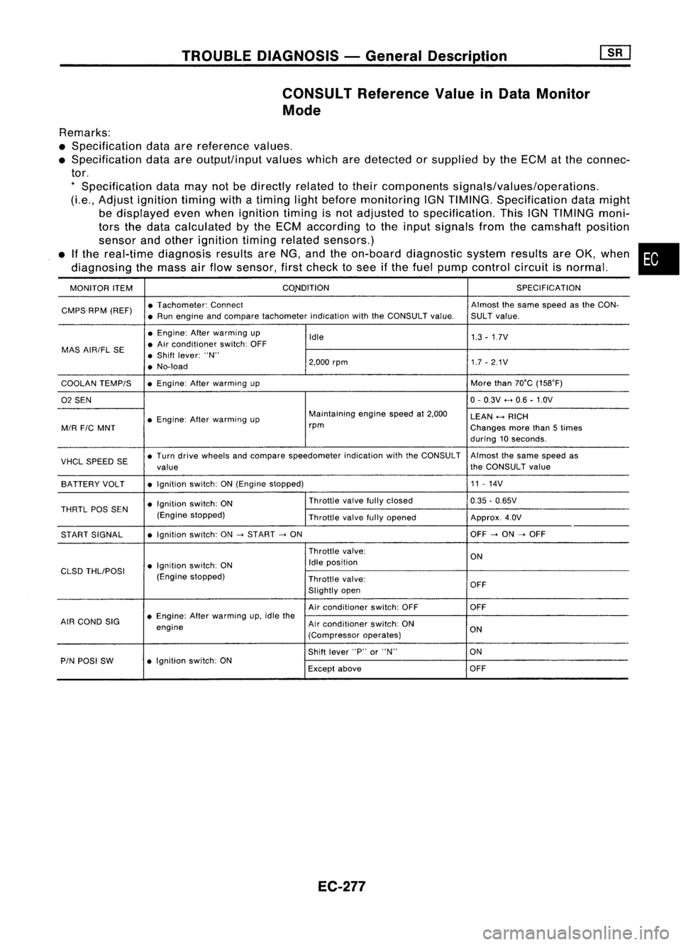
CONSULT Reference ValueinData Monitor
Mode
Remarks:
• Specification dataarereference values.
• Specification dataareoutput/input valueswhicharedetected orsupplied bythe ECM atthe connec-
tor.
*
Specification datamaynotbedirectly relatedtotheir components signals/values/operations.
(Le., Adjust ignition timingwithatiming lightbefore monitoring IGNTIMING. Specification datamight
be displayed evenwhen ignition timingisnot adjusted tospecification. ThisIGNTIMING moni-
tors thedata calculated bythe ECM according tothe input signals fromthecamshaft position
sensor andother ignition timingrelated sensors.)
• Ifthe real-time diagnosis resultsareNG, andtheon-board diagnostic systemresultsareOK, when •
diagnosing themass airflow sensor, firstcheck tosee ifthe fuel pump control circuitisnormal.
MONITOR ITEM CONDITION
SPECIFICATION
CMPS.RPM (REF)•
Tachometer: Connect Almostthesame speed asthe CON-
• Run engine andcompare tachometer indicationwiththeCONSULT value.SULTvalue.
• Engine: Afterwarming up
Idle 1.3-1.7V
MAS AIR/FL SE •
Air conditioner switch:OFF
• Shift lever: "N"
• No-load 2,000
rpm 1.7-2.1V
COOLAN TEMPIS •
Engine: Afterwarming up More
than70°C (15S0F)
02 SEN 0-
0.3V .....0.6 -1.0V
• Engine: Afterwarming up Maintaining
enginespeedat2,000
LEAN
+-->
RICH
MIR
FIC
MNT rpm
Changesmorethan5times
during 10seconds.
VHCL SPEED SE•
Turn drive wheels andcompare speedometer indicationwiththeCONSULT Almostthesame speed as
value the
CONSULT value
BATTERY VOLT •
Ignition switch:ON(Engine stopped) 11
-14V
• Ignition switch:ON Throttle
valvefullyclosed
0.35-0.65V
THRTL
pas
SEN
(Enginestopped)
Throttlevalvefullyopened Approx.4.0V
START SIGNAL •
Ignition switch:ON
->
START
->
ON OFF
->
ON
->
OFF
Throttle valve:
ON
• Ignition switch:ON Idle
position
CLSD THLIPOSI
(Enginestopped)
Throttlevalve:
Slightly open OFF
Air conditioner switch:OFF OFF
AIR COND SIG •
Engine: Afterwarming up,idle the
engine Air
conditioner switch:ON
ON
(Compressor operates)
Shift lever "P"or"N" ON
PIN POSI SW •
Ignition switch:ON
Exceptabove OFF
EC-277
Page 997 of 1701
![NISSAN ALMERA N15 1995 Service Manual TROUBLEDIAGNOSIS -General Description
[]K]
CONSULT Reference ValueinData Monitor
Mode (Cont'd)
MONITOR ITEM
CONDITION SPECIFICATION
Steering wheelinneutral
position OFF
PW/ST SIGNAL
•Engine: NISSAN ALMERA N15 1995 Service Manual TROUBLEDIAGNOSIS -General Description
[]K]
CONSULT Reference ValueinData Monitor
Mode (Cont'd)
MONITOR ITEM
CONDITION SPECIFICATION
Steering wheelinneutral
position OFF
PW/ST SIGNAL
•Engine:](/manual-img/5/57349/w960_57349-996.png)
TROUBLEDIAGNOSIS -General Description
[]K]
CONSULT Reference ValueinData Monitor
Mode (Cont'd)
MONITOR ITEM
CONDITION SPECIFICATION
Steering wheelinneutral
position OFF
PW/ST SIGNAL
•Engine: Afterwarming up,idle theengine (forward
direction)
The steering wheelis
ON
turned
• Engine: Afterwarming up
Idle2.5-3.7 msec .
INJ PULSE •
Air conditioner switch:OFF
• Shift lever: "N"
• No-load 2,000
rpm 1.9-2.8 msec .
Idle 13-15° BTDC
IGN TIMING
ditto
2,000rpm Morethan25°BTDC
Idle 20-40%
IACV-AACIV ditto
2,000rpm
-
A/F ALPHA •Engine: Afterwarming up Maintaining
enginespeed
53-155%
at 2.000 rpm
AIR COND RLY •Air conditioner switch:OFF
-+
ON OFF
-+
ON
• Ignition switchis~urned toON (Operates for5seconds)
• Engine running andcranking ON
FUEL PUMP RLY
•When engine isstopped (stopsin1.0 seconds)
• Except asshown above OFF
Engine coolant temperature
is 94°C (201°F) orless for
AfT models. and99°C OFF
(210°F) orless for
M/T
mod-
els
• After warming upengine. idletheengine. Engine
coolant temperature
is between 95°C(203°F) and
COOLING FAN •Air conditioner switch:OFF
104°C(219°F) forA/T mod- LOW
• Vehicle stopped
elsonly
Engine coolant temperature
is 105°C (221°F) ormore for
A/T
models. and100°C HIGH
(212°F) ormore for
M/T
models
• Engine: Afterwarming up
IdleON
EGRC SOLIV •
Air conditioner switch:OFF
• Shift lever: "N"
• No-load 2.000
rpm OFF
EC-278
Page 1004 of 1701
![NISSAN ALMERA N15 1995 Service Manual TROUBLEDIAGNOSIS -General Description
[]K]
ECM Terminals andReference Value(Cont'd)
'Data arereference values.
TERMINAL WIRE
ITEM CONDITION
'DATA
NO. COLOR
Ilgnitionswitch"ON"I
NISSAN ALMERA N15 1995 Service Manual TROUBLEDIAGNOSIS -General Description
[]K]
ECM Terminals andReference Value(Cont'd)
'Data arereference values.
TERMINAL WIRE
ITEM CONDITION
'DATA
NO. COLOR
Ilgnitionswitch"ON"I](/manual-img/5/57349/w960_57349-1003.png)
TROUBLEDIAGNOSIS -General Description
[]K]
ECM Terminals andReference Value(Cont'd)
'Data arereference values.
TERMINAL WIRE
ITEM CONDITION
'DATA
NO. COLOR
Ilgnitionswitch"ON"I
L
For 5seconds afterturning ignition switch
"ON" Approximately
OV
104 B/P Fuelpump relay !Engine
isrunning.1
Ilgnition switch"ON"I
BATTERY VOLTAGE
L
5seconds afterturning ignitionswitch
(11-14V)
"ON" andthereafter
IEngine isrunning.1
0.6-0.8V
EGR valve
&
EVAP
.L
Engine speedis4,000 rpm.
105 P canisterpurgecontrol
solenoid valve IEngine
isrunning.1
BATTERYVOLTAGE
L
Idle speed (11
-14V)
107 IEngine
isrunning.j
B/Y ECCSground
L
Engine
ground
108 Idlespeed
!Engine isrunning.1
Approximately0.2V
L
Engine speedisbelow 3,200rpm.
Heated oxygen sensor
111 OR
heater IEngineisrunning.1
BATTERY VOLTAGE
L
Engine speedisabove 3,200rpm. (11
-14V)
IEngine isrunning.\
11-14V
L
Idle speed
113 SB IACV-AAC
valve lEngine
isrunning.1
~ Sle«;ng wheel;,be;ng I"med
2-11V
Air conditioner isoperating.
Rear window defogger switchis"ON".
Lighting switchis"ON".
!Engine isrunning.1
ApproximatelyOV
Torque converter
L
Idle speed
115 P/B clutch
solenoid valve
IEngineisrunning.1 (Warm-up condition)
(A/T
models)
L
Vehicle speedis60 km/h (37MPH) or BA
TTERY VOLTAGE
(11 -14V)
more in"D" position
116 BIY ECCS
ground IEngine
isrunning.1
Engineground
L
Idle speed
EC-285
•
Page 1008 of 1701
TROUBLEDIAGNOSIS FOROTC11
Rotor plate
SEF6138
180
0
signal slitfor NO.1 cylinder
\\\\""I"~'11111
1
0
signal slit
\\\\\ d'"
/11;
:£
';\'0\
I//..;:
#'
/%
$ ~
180
0
signal slit
f
0
%
o
Camshaft
PositionSensor(CMPS)
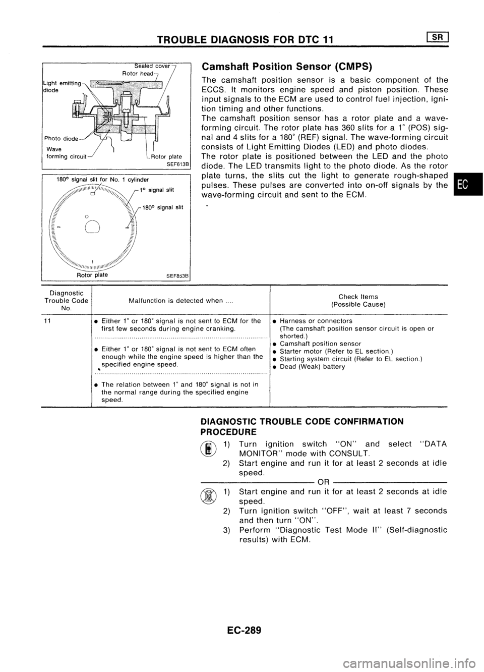
The camshaft positionsensorisabasic component ofthe
ECCS. Itmonitors enginespeedandpiston position. These
input signals tothe ECM areused tocontrol fuelinjection, igni-
tion timing andother functions.
The camshaft positionsensorhasarotor plate andawave-
forming circuit.Therotor plate has360slits fora
1"
(POS) sig-
nal and 4slits fora180
0
(REF) signal. Thewave-forming circuit
consists ofLight Emitting Diodes(LED)andphoto diodes.
The rotor plate ispositioned betweentheLED andthephoto
diode. TheLED transmits lighttothe photo diode. Asthe rotor
plate turns, theslits cutthe light togenerate rough-shaped •
pulses. Thesepulses areconverted intoon-off signals bythe
wave-forming circuitandsent tothe ECM.
Rotor plate
SEF8638
Diagnostic
Trouble Code
No.
11
Malfunction
isdetected when....
• Either 1
0
or 180
0
signal isnot sent toECM forthe
first fewseconds duringengine cranking.
• Either
r
or 180" signal isnot sent toECM often
enough whiletheengine speedishigher thanthe
specified enginespeed.
~
• The relation between rand180
0
signal isnot in
the normal rangeduring thespecified engine
speed. Check
Items
(Possible Cause)
• Harness orconnectors
(The camshaft positionsensorcircuitisopen or
shorted.)
• Camshaft positionsensor
• Starter motor(Refer toEL section.)
• Starting systemcircuit(RefertoEL section.)
• Dead (Weak) battery
3)
@
1)
2)
DIAGNOSTIC
TROUBLECODECONFIRMATION
PROCEDURE
rif\
1)Turn ignition switch"ON"andselect "DATA
~ MONITOR" modewithCONSULT.
2) Start engine andrunitfor atleast 2seconds atidle
speed.
---------- OR----------
Start engine andrunitfor atleast 2seconds atidle
speed.
Turn ignition switch"OFF", waitatleast 7seconds
and then turn"ON".
Perform "Diagnostic TestMode II"(Self-diagnostic
results) withECM.
EC-289
Page 1012 of 1701
TROUBLEDIAGNOSIS FOROTe12
•
Check
Items
(Possible Cause)
Mass
AirFlow Sensor (MAFS)
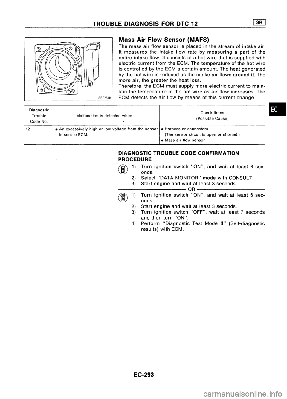
The mass airflow sensor isplaced inthe stream ofintake air.
It measures theintake flowratebymeasuring apart ofthe
entire intake flow.Itconsists ofahot wire thatissupplied with
electric currentfromtheECM. Thetemperature ofthe hotwire
is controlled bythe ECM acertain amount. Theheat generated
by the hotwire isreduced asthe intake airflows around it.The
more air,thegreater theheat loss.
Therefore, theECM mustsupply moreelectric currenttomain-
tain thetemperature ofthe hotwire asair flow increases. The
SEF781K
ECMdetects theairflow bymeans ofthis current change.
Malfunction isdetected when...
Diagnostic
Trouble
Code No.
12
•An excessively highorlow voltage fromthesensor •Harness orconnectors
is sent toECM. (Thesensor circuitisopen orshorted.)
• Mass airflow sensor
DIAGNOSTIC TROUBLECODECONFIRMATION
PROCEDURE
fiii\
1)Turn ignition switch"ON",andwait atleast 6sec-
~ onds.
2) Select "DATA MONITOR" modewithCONSULT.
3) Start engine andwait atleast 3seconds.
---------- OR----------
rR\
1)Turn ignition switch"ON",andwait atleast 6sec-
~ onds.
2) Start engine andwait atleast 3seconds.
3) Turn ignition switch"OFF", waitatleast 7seconds
and then turn"ON".
4) Perform "Diagnostic TestMode II"(Self-diagnostic
results) withECM.
EC-293
Page 1016 of 1701
TROUBLEDIAGNOSIS FOROTC13
20
19
6
9
4
~ 2
~ 1.0
1ij
0.8
'w
8!
04
0.2
0.1
.20 020 40 6080100
(-4) (32) (68)(104)(140)(176)(212)
Temperature 'C
(OF)
SEF594K
SEF012P Engine
Coolant Temperature Sensor(ECTS)
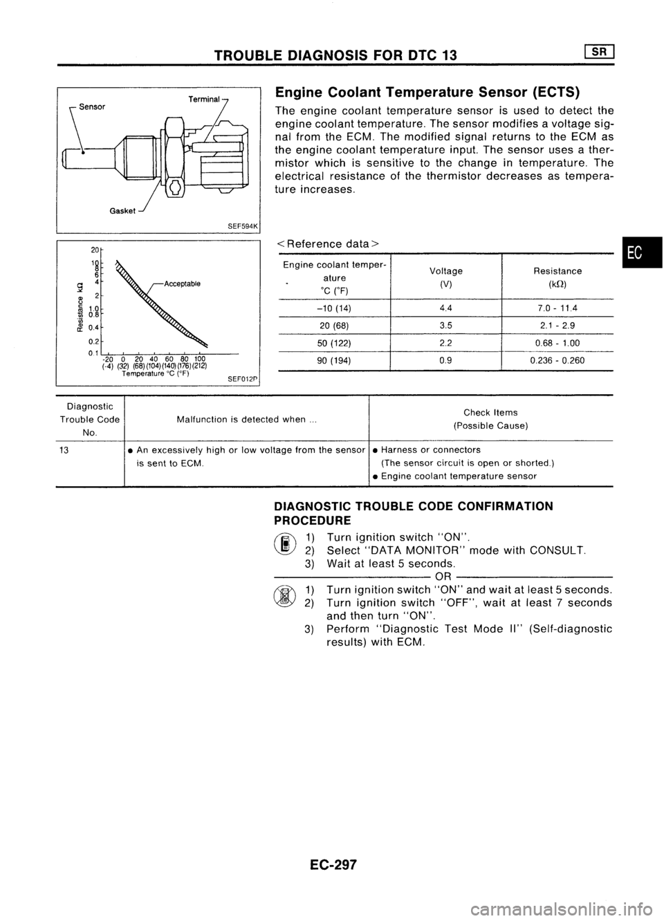
The engine coolant temperature sensorisused todetect the
engine coolant temperature. Thesensor modifies avoltage sig-
nal from theECM. Themodified signalreturns tothe ECM as
the engine coolant temperature input.Thesensor usesather-
mistor whichissensitive tothe change intemperature. The
electrical resistance ofthe thermistor decreases astempera-
ture increases.
<
Reference data>
Engine coolant temper-
Voltage Resistance
ature
.
(V)(kQ)
'C ("F)
-10 (14) 4.4
7.0-11.4
20 (68) 3.5
2.1-2.9
50 (122) 2.20.68-1.00
90 (194) 0.9
0.236-0.260
•
Diagnostic
Trouble Code
No. Malfunction
isdetected when... Check
Items
(Possible Cause)
13 •
An excessively highorlow voltage fromthesensor •Harness orconnectors
is sent toECM. (Thesensor circuitisopen orshorted.)
• Engine coolant temperature sensor
DIAGNOSTIC TROUBLECODECONFIRMATION
PROCEDURE
rF.i\
1)Turn ignition switch"ON".
~ 2)Select "DATA MONITOR" modewithCONSULT.
3) Wait atleast 5seconds.
---------- OR----------
rm
1)Turn ignition switch"ON"andwait atleast 5seconds.
~ 2)Turn ignition switch"OFF", waitatleast 7seconds
and then turn"ON".
3) Perform "Diagnostic TestMode II"(Self-diagnostic
results) withECM.
EC-297
Page 1020 of 1701
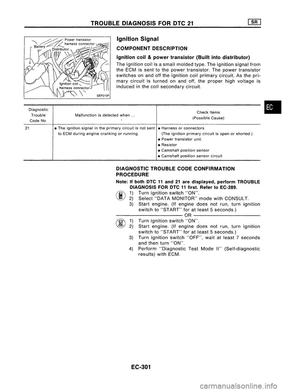
TROUBLEDIAGNOSIS FORDTC21
Ignition Signal
COMPONENT DESCRIPTION
Ignition coil
&
power transistor (Builtintodistributor)
The ignition coilisasmall molded type.Theignition signalfrom
the ECM issent tothe power transistor. Thepower transistor
switches onand offthe ignition coilprimary circuit.Asthe pri-
mary circuit isturned onand off,the proper highvoltage is
induced inthe coil secondary circuit.
Diagnostic Trouble
Code No.
21
Malfunction
isdetected when...
• The ignition signalinthe primary circuitisnot sent
to ECM during engine cranking orrunning. Check
Items
(Possible Cause)
• Harness orconnectors
(The ignition primary circuitisopen orshorted.)
• Power transistor unit.
• Resistor
• Camshaft positionsensor
• Camshaft positionsensorcircuit
•
DIAGNOSTIC TROUBLECODECONFIRMATION
PROCEDURE
Note: Ifboth DTC11and 21are displayed, performTROUBLE
DIAGNOSIS FORDTC11first. Refer toEC-289.
(F.I\ 1)Turn ignition switch"ON".
~ 2)Select "DATA MONITOR" modewithCONSULT.
3) Start engine. (Ifengine doesnotrun, turn ignition
switch to"START" foratleast 5seconds.)
---------- OR----------
~ 1)Turn ignition switch"ON".
~ 2)Start engine. (Ifengine doesnotrun, turn ignition
switch to"START" foratleast 5seconds.)
3) Turn ignition switch"OFF", waitatleast 7seconds
and then turn"ON".
4) Perform "Diagnostic TestMode II"(Self-diagnostic
results) withECM.
EC-301