Page 1175 of 1701
ENGINECOOLING SYSTEM
I
GA, SR,CD
I
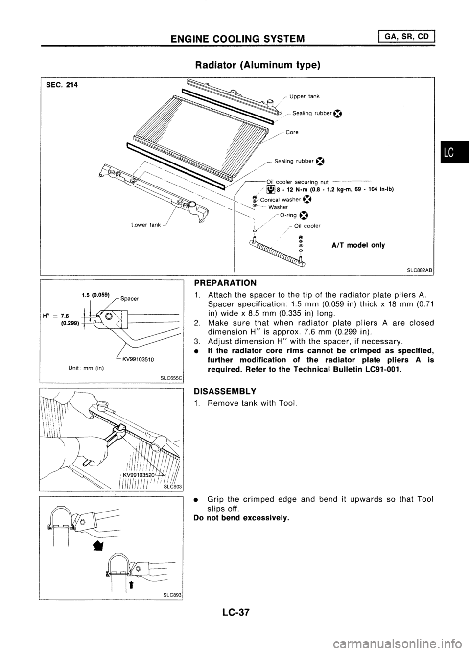
Radiator (Aluminum type)
r
Sealing rubber~
•
SLC882AB
AIT
model only
r
Upper tank
Sealing rubber~
/"""-.
CJ~~ /~.........."-. '-.. ....,
1I
. / -~ '-""", /~Oil coolersecuring nut-
~ ~,>" (
6<,~8 •
12 N.m
(0.8•1.2 kg-m,
69-104
In-Ib)
@
0..~
~>..
!--Conicalwasher~
, ~I"~"-
Washer
/ /~, ,-O-ring~
Lower tank
-.I
I/' ,_
Oil cooler
o
,
SEC.
214
1.5(0.059)
H"
=
7.6
(0.299)
Unit: mm(in)
PREPARATION
1. Attach thespacer tothe tipofthe radiator platepliers A.
Spacer specification: 1.5mm (0.059 in)thick x18 mm (0.71
in) wide x8.5 mm (0.335 in)long.
2. Make surethatwhen radiator platepliers Aare closed
dimension H"isapprox. 7.6mm (0.299 in).
3. Adjust dimension H"with thespacer, ifnecessary.
• Ifthe radiator corerimscannot becrimped asspecified,
further modification ofthe radiator platepliers Ais
required. Refertothe Technical BulletinLC91-001.
SLC655C
D1SASSEMBL Y
1. Remove tankwithTool.
• Grip thecrimped edgeandbend itupwards sothat Tool
slips off.
Do not bend excessively.
*
LC-37
Page 1176 of 1701
ENGINECOOLING SYSTEM
I
GA, SR,CD
I
Radiator (Aluminum type)(Cont'd)
• Inareas where Toolcannot beused, useascrewdriver to
bend theedge up.
Be careful nottodamage tank.
2. Make suretheedge stands straight up.
3. Remove oilcooler fromtank.
(AfT
models only)
SLC931 ASSEMBLY
1. Install oilcooler.
(AfT
models only)
Pay attention todirection ofconical washer.
~ Conical washer~
SLCB94
2.Clean contact portionoftank.
SLC932
3.Install sealing rubber.
Push itin with fingers.
Be careful nottotwist sealing rubber.
LC-38
Page 1217 of 1701
I
Recess
1
diameter
I
SEM795A CYLINDER
HEAD
Inspection (Cont'd)
VALVE SEATS
Check valveseats forpitting atcontact surface. Resurface or
replace ifexcessively worn.
• Before repairing valveseats, checkvalveandvalve guide
for wear. Ifthey have worn, replace them.Thencorrect
valve seat.
• Cut with both hands touniform thecutting surface.
REPLACING VALVESEATFORSERVICE PARTS
1. Bore outold seat until
it
collapses. Setmachine depthstop
so that boring cannot contact bottomfaceofseat recess in
cylinder head.
2. Ream cylinder headrecess.
Reaming boreforservice valveseat
Oversize [0.5mm(0.020 in)]:
Unit:mm(in)
Engine model GA16DE
withoutVTC,
GA16DE withVTC
14DE and15DE
30.500 -30.516
Intake (1.2008
-1.2014)
31.500-31.516
31.500 -31.516
(1.2402-1.2408)
(1.2402 -1.2408).
Exhaust 25.500
-25.516
26.500-26.516
(1.0039 -1.0046)
(1.0433-1.0439)
.: GA 16DE without VTC
Use thevalve guide center forreaming toensure valveseatwill
have thecorrect fit.
EM-38
Page 1234 of 1701
AEM030
SEM062A
SEM291C
SEM367E CYLINDER
BLOCK ~
Inspection (ConI'd)
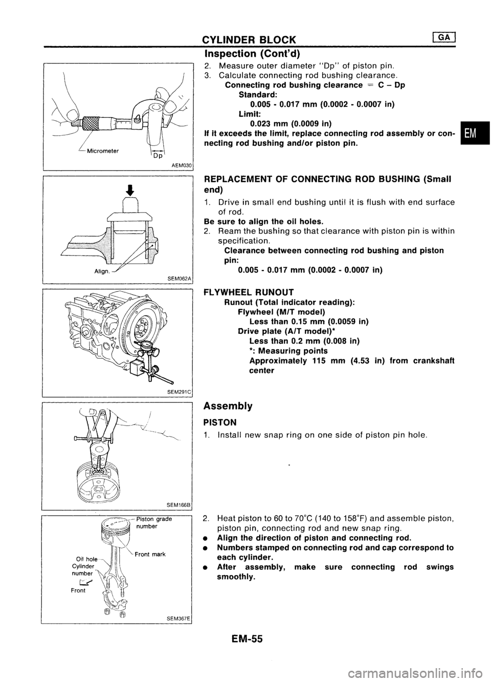
2. Measure outerdiameter lOOp"ofpiston pin.
3. Calculate connecting rodbushing clearance.
Connecting rodbushing clearance
=
C-Dp
Standard: 0.005 •0.017 mm(0.0002 •0.0007 in)
Limit:
0.023 mm(0.0009 in) •
If itexceeds thelimit, replace connecting rodassembly orcon-
necting rodbushing andlorpistonpin.
REPLACEMENT OFCONNECTING RODBUSHING (Small
end)
1. Drive insmall endbushing untilitis flush withendsurface
of rod.
Be sure toalign theoilholes.
2. Ream thebushing sothat clearance withpiston piniswithin
specification.
Clearance betweenconnecting rodbushing andpiston
pin: 0.005 -0.017 mm(0.0002 -0.0007 in)
FLYWHEEL RUNOUT
Runout (Totalindicator reading):
Flywheel (MITmodel)
Less than0.15mm(0.0059 in)
Drive plate(AITmodel)*
Less than0.2mm (0.008 in)
*:
Measuring points
Approximately 115mm (4.53 in)from crankshaft
center
Assembly PISTON
1. Install newsnap ringonone side ofpiston pinhole.
2. Heat piston to60 to70°C (140to158°F) andassemble piston,
piston pin,connecting rodand new snap ring.
• Align thedirection ofpiston andconnecting rod.
• Numbers stampedonconnecting rodand capcorrespond to
each cylinder.
• After assembly, makesureconnecting rodswings
smoothly.
EM-55
Page 1235 of 1701
Punchmarksideup
(if mark ispresent.)
SEM965E CYLINDER
BLOCK @KJ
Assembly (Coni'd)
3. Set piston ringsasshown.
CAUTION:
• When piston ringsarenotreplaced, makesurethatpiston
rings aremounted intheir original position.
• When piston ringsarebeing replaced andnopunch mark
is present, pistonringscanbemounted witheither sideup.
For Europe andIsrael models
Engine
front
Q
Oil
ring
expander
tf
V
;l
Top and second ring
Punch marksideup
(if mark ispresen!.)
.::::::::J
c::
Oil ring
expander
*c:
Engine
il
front
~ •
Top ring
• Oil ring
~ upperrail
IJ
/') Oilring
~ ~lower rail
SEM160B
SEM208F
Top ring
Oil ring
~ It
upper rail
!J
~.Oil ring
lower rail
SEM200F Except
forEurope andIsrael models
#5
#4 ~
Oil hole #3 ~-'U
~"\)~ ~
~~
Oilgroove
SEM366E
CRANKSHAFT
1. Set main bearings intheir proper positions oncylinder
block andmain bearing cap.
• Confirm thatcorrect mainbearings areused. Referto
"Inspection" (EM-52).
• Apply engine oiltobearing surfaces.
EM-56
Page 1357 of 1701
SGI916PRECAUTIONS
• Donot use electrical testequipment onany circuit related •
to the SRS unless instructed tointhis Service Manual.
Precautions forNATS V2.0(ForGasoline Engine
Model)
NATS (Nissan Anti-Theft System)
NATS V2.0willimmobilize theengine ifsomeone triestostart
it without theregistered keyofNATS V2.0.
Both ofthe originally suppliedignitionkeyIDshave been NATS
registered.
The NATS security indicator islocated onthe instrument panel.
The indicator blinkswhentheignition switchisin "OFF" or
"ACC" position. Therefore, NATSwarns outsiders thatthevehi-
cle isequipped withtheanti-theft system.
• When NATSdetects trouble, themalfunction indicatorlamp
(MIL) blinks.
This blinking indicates thattheanti-theft isnot functioning,
so prompt service isrequired.
• When servicing NATS(trouble diagnoses, systeminitialisa-
tion andadditional registration ofother NATS ignition key
IDs), CONSULT hardwareandCONSULT NATSsoftware is
necessary.
Regarding theprocedures ofNATS initialisation andNATS
ignition key
10
registration, refertoCONSULT operation
manual, NATSV2.0.
Therefore, CONSULTNATSsoftware (program cardandoper-
ation manual) mustbekept strictly confidential tomaintain the
integrity ofthe anti-theft function.
• When servicing NATSV2.0(trouble diagnoses, systemini-
tial isation andadditional registration ofother NATS ignition
key IDs),
it
may benecessary tore-register originalkey
identification. Therefore,besure toreceive allkeys from
vehicle owner.
A maximum offour keyIDscan beregistered intoNATS.
• When failing tostart theengine first-time usingthekey of
NATS V2.0,startasfollows.
(1) Turn ignition keyto"OFF".
(2) Wait approx. 5seconds.
(3) Turn ignition keyto"START" againwhilekeeping the
key apart fromanyothers onkey-chain.
SGI285 General
Precautions
• Donot operate theengine foranextended periodoftime
without properexhaust ventilation.
Keep thework areawellventilated andfree ofany flamma-
ble materials. Specialcareshould betaken whenhandling
any flammable orpoisonous materials,suchasgasoline,
refrigerant gas,etc.When working inapit orother enclosed
area, besure toproperly ventilate thearea before working
with hazardous materials.
Do not smoke whileworking onthe vehicle.
GI-3
Page 1372 of 1701
HOWTOPERFORM EFFICIENT DIAGNOSIS FORANELECTRICAL INCIDENT
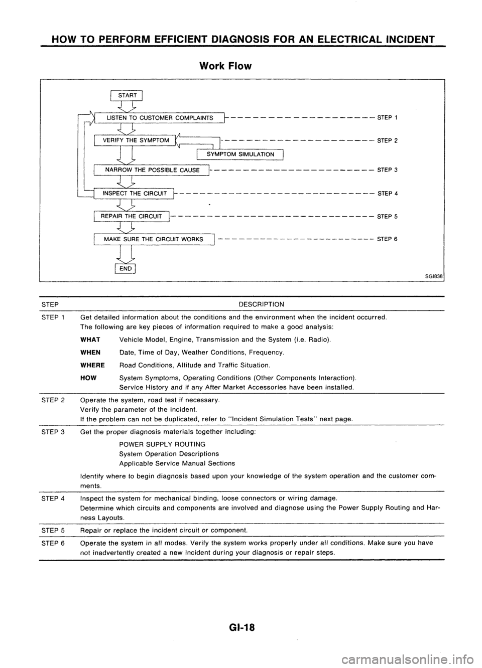
Work Flow
- - - -- - -- ------ -- - -- STEP 1
--------------------- STEP2
----------------------- STEP3
- - -- ---- - --- - -- --- --- - - --- -- STEP 4
--------- -------------------- STEP5
- - - - ---- -- -- -- -- -- --- --- STEP 6
SGI838
STEP
STEP 1 DESCRIPTION
Get detailed information abouttheconditions andtheenvironment whentheincident occurred.
The following arekey pieces ofinformation requiredtomake agood analysis:
HOW
WHEN
WHAT
WHERE
Vehicle
Model,Engine, Transmission andtheSystem (i.e.Radio).
Date, TimeofDay, Weather Conditions, Frequency.
Road Conditions, AltitudeandTraffic Situation.
System Symptoms, OperatingConditions (OtherComponents Interaction).
Service Historyandifany After Market Accessories havebeen installed.
Operate thesystem, roadtestifnecessary.
Verify theparameter ofthe incident.
If the problem cannotbeduplicated, referto"Incident Simulation Tests"nextpage.
STEP
2
STEP 3Get
theproper diagnosis materialstogetherincluding:
POWER SUPPLY ROUTING
System Operation Descriptions
Applicable ServiceManualSections
Identify wheretobegin diagnosis baseduponyourknowledge ofthe system operation andthecustomer com-
ments.
STEP 4
STEP 5
STEP 6 Inspect
thesystem formechanical binding,looseconnectors orwiring damage.
Determine whichcircuits andcomponents areinvolved anddiagnose usingthePower Supply Routing andHar-
ness Layouts.
Repair orreplace theincident circuitorcomponent.
Operate thesystem inall modes. Verifythesystem worksproperly underallconditions. Makesureyouhave
not inadvertently createdanew incident duringyourdiagnosis orrepair steps.
GI-18
Page 1397 of 1701
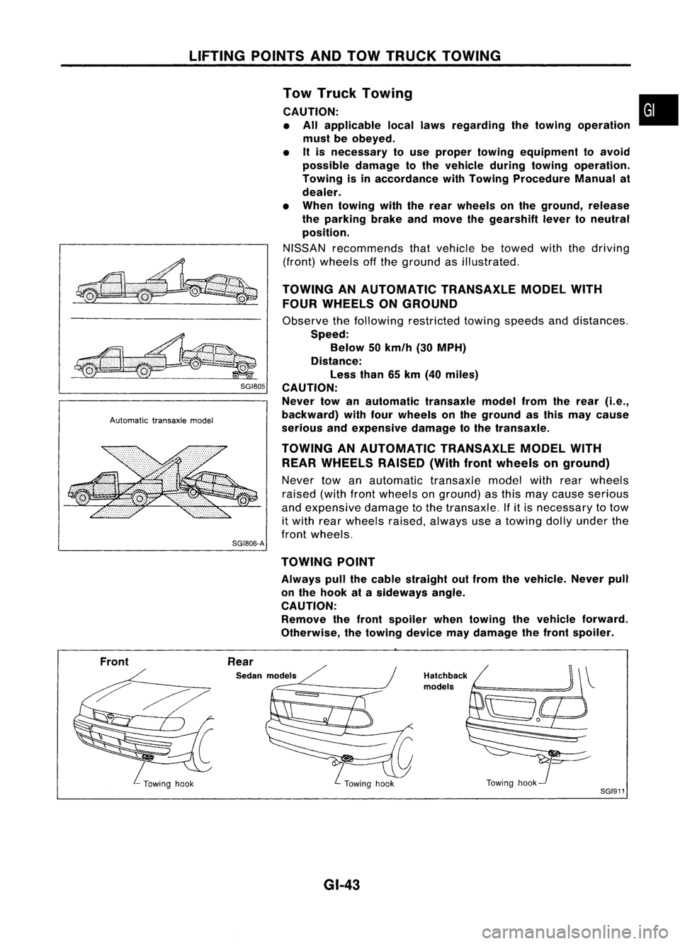
LIFTINGPOINTSANDTOW TRUCK TOWING
~ SGI80S
Automatic transaxlemodel
SG1806-A Tow
Truck Towing •
CAUTION: • All applicable locallawsregarding thetowing operation
must beobeyed.
• Itis necessary touse proper towing equipment toavoid
possible damagetothe vehicle duringtowing operation.
Towing isinaccordance withTowing Procedure Manualat
dealer.
• When towing withtherear wheels onthe ground, release
the parking brakeandmove thegearshift levertoneutral
position.
NISSAN recommends thatvehicle betowed withthedriving
(front) wheels offthe ground asillustrated.
TOWING ANAUTOMATIC TRANSAXLEMODELWITH
FOUR WHEELS ONGROUND
Observe thefollowing restricted towingspeeds anddistances.
Speed: Below 50km/h (30MPH)
Distance: Less than65km (40 miles)
CAUTION: Never towanautomatic transaxlemodelfromtherear
(i.e.,
backward) withfourwheels onthe ground asthis may cause
serious andexpensive damagetothe transaxle.
TOWING ANAUTOMATIC TRANSAXLEMODELWITH
REAR WHEELS RAISED(Withfrontwheels onground)
Never towanautomatic transaxlemodelwithrearwheels
raised (withfrontwheels onground) asthis may cause serious
and expensive damagetothe transaxle. Ifitis necessary totow
it with rearwheels raised,always useatowing dollyunder the
front wheels.
TOWING POINT
Always pullthecable straight outfrom thevehicle. Neverpull
on the hook atasideways angle.
CAUTION: Remove thefront spoiler whentowing thevehicle forward.
Otherwise, thetowing devicemaydamage thefront spoiler.
Front Rear
Sedan models
GI-43
Hatchback
models
Towinghook
SGI911