Page 876 of 1701
TROUBLEDIAGNOSIS FORNON-DETECTABLE ITEMS
Cooling FanControl (Cont'd)
AIT MODELS
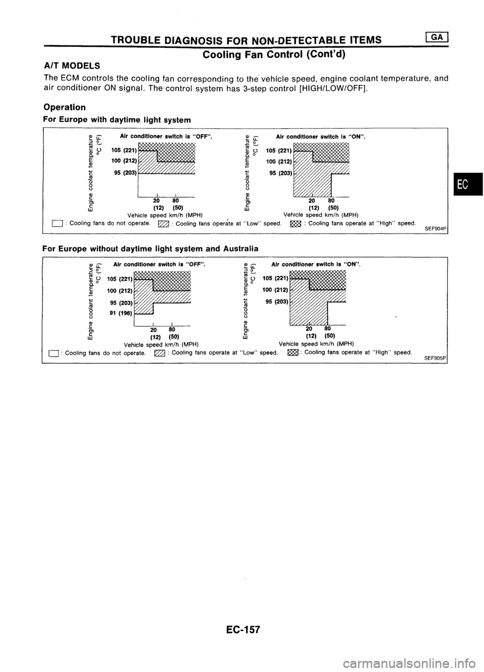
The ECM controls thecooling fancorresponding tothevehicle speed,engine coolant temperature, and
air conditioner ONsignal. Thecontrol system has3-step control
[HIGH/LOW/OFF],
Operation
For Europe withdaytime lightsystem
•
SEF904P
Air
conditioner switchIs"ON".
105 (221)
100 (212)
95 (203)
Air
conditioner switchIs"OFF".
95 (203)
105
(221)
100 (212)
C
'0
o
()
Q)
c
'0>
c
UJ
~
iL
::J
0
e;-
~o
E
~
C
'0
o
()
Q)
~ 00
i~
00
(12) (50)
tD
(12)(50)
Vehicle speedkm/h(MPH) Vehiclespeedkm/h(MPH)
o :
Cooling fansdonot operate. ~:Cooling fansoperate at"Low" speed. ~:Cooling fansoperate at"High" speed.
For Europe withoutdaytime lightsystem andAustralia
SEF905P
Air
conditioner switchis"ON",
105 (221)
100 (212)
95 (203)
Air
conditioner switchIs"OFF".
95 (203)
91 (196)
105
(221)
100 (212)
~
'0
o
()
Q)
c
'0>
c
UJ
~~
::J
0
(;j-
.... 0
~o
E
2
C
'0
o
()
Q)
~ 00
i~
00
(12) (50)
tD
(12)(50)
Vehicle speedkm/h(MPH) Vehiclespeedkm/h(MPH)
o :
Cooling fansdonot operate.
l22a:
Cooling fansoperate at"Low" speed. ~:Cooling fansoperate at"High" speed.
EC-157
Page 881 of 1701
Checkcooling fanlow
speed control circuit.
(Go to
I
PROCEDURE A
I.)
Check cooling fanhigh
speed control circuit.
(Go to
I
PROCEDURE B
I.)
NG
NG
OK
INSPECTION
START
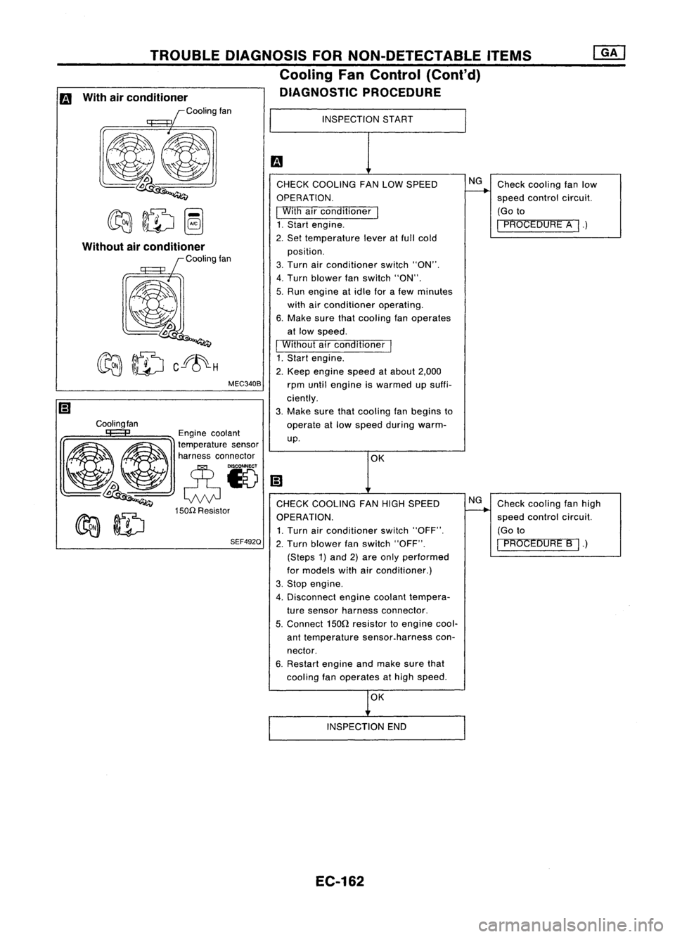
CHECK COOLING FANLOW SPEED
OPERATION.
I
With airconditioner
I
1. Start engine.
2. Set temperature leveratfull cold
position.
3. Turn airconditioner switch"ON".
4. Turn blower fanswitch "ON".
5. Run engine atidle forafew minutes
with airconditioner operating.
6. Make surethatcooling fanoperates
at low speed.
I
Without airconditioner
I
1. Start engine.
2. Keep engine speedatabout 2,000
rpm until engine iswarmed upsuffi-
ciently.
3. Make surethatcooling fanbegins to
operate atlow speed during warm-
up.
MEC340B
TROUBLE
DIAGNOSIS FORNON-DETECTABLE ITEMS
Cooling FanControl (Cant'd)
DIAGNOSTIC PROCEDURE
Cooling fan
Without
airconditioner
Coolingfan
Engine coolant
~ ~ ~a~~:;:t:a::;'~~'
~~ eN
lDoo
Q
CHECKCOOLING FANHIGH SPEED
150n
Resistor
~ ~ OPERATION.
~ ~ 1.Turn airconditioner switch"OFF".
SEF492Q
2.Turn blower fanswitch "OFF".
(Steps 1)and 2)are only performed
for models withairconditioner.)
3. Stop engine.
4. Disconnect enginecoolant tempera-
ture sensor harness connector.
5.
Connect
1500
resistor toengine cool-
ant temperature sensor.harness con-
nector.
6. Restart engineandmake surethat
cooling fanoperates athigh speed.
m
With airconditioner
Coolingfan
OK
INSPECTION END
EC-162
Page 883 of 1701
Ii
1
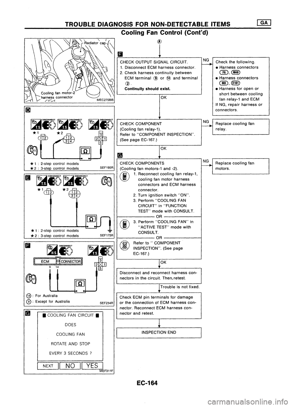
CHECK OUTPUT SIGNALCIRCUIT. NG
Check thefollowing.
1. Disconnect ECMharness connector. ~
•Harness connectors
2. Check harness continuity between
aD,@
ECM terminal @or@ and terminal •
Harness connectors
@.
@,@D
Continuity shouldexist. •
Harness foropen or
OK short
between cooling
Ian relay-1 andECM
If NG, repair harness or
connectors.
CHECK COMPONENT NG
Replace coolingfan
(Cooling fanrelay-1).
---+
relay.
Refer to"COMPONENT INSPECTION".
(See page EC-167.)
OK
[!1
CHECK COMPONENTS NG
Replace coolingfan
(Cooling fanmotors-1 and-2).
---+
motors.
00
1.
Reconnect coolingfanrelay-1,
cooling fanmotor harness
connectors andECM harness
connector.
2. Turn ignition switch"ON".
3. Perform "COOLING FAN
CIRCUIT" in"FUNCTION
TEST" modewithCONSULT.
OR
00
3.
Perform "COOLING FAN"in
"ACTIVE TEST"modewith
CONSULT. OR
@ Refer
to"COMPONENT
INSPECTION". (Seepage
EC-167.)
OK
Disconnect andreconnect harnesscon-
nectors inthe circuit. Then.retest.
Trouble isnot fixed.
Check ECMpinterminals fordamage
or the connection 01ECM harness con-
nector. Reconnect ECMharness con-
nector andretest.
INSPECTION END
SEF175R
SEF195R
SEF234R
TROUBLE
DIAGNOSIS FORNON-DETECTABLE ITEMS
Cooling FanControl (Cont'd)
@
COOLING FAN
•
COOLING FANCIRCUIT.
DOES
~i5
ECM E
CONNEc@1
9 14
II
*
1: 2-step control models
*
2:3-step control models
*
1:2-step control models
* 2:3-step control models
@:
ForAustralia
(2):
Except lorAustralia
Ii
ROTATEANDSTOP
EVERY 3SECONDS
?
NEXT
II
NO
11
YES
I
MEF311F
EC-164
Page 885 of 1701
TROUBLEDIAGNOSIS FORNON-DETECTABLE ITEMS
Cooling FanControl (Cont'd)
@
o
~i5
~-
m=m
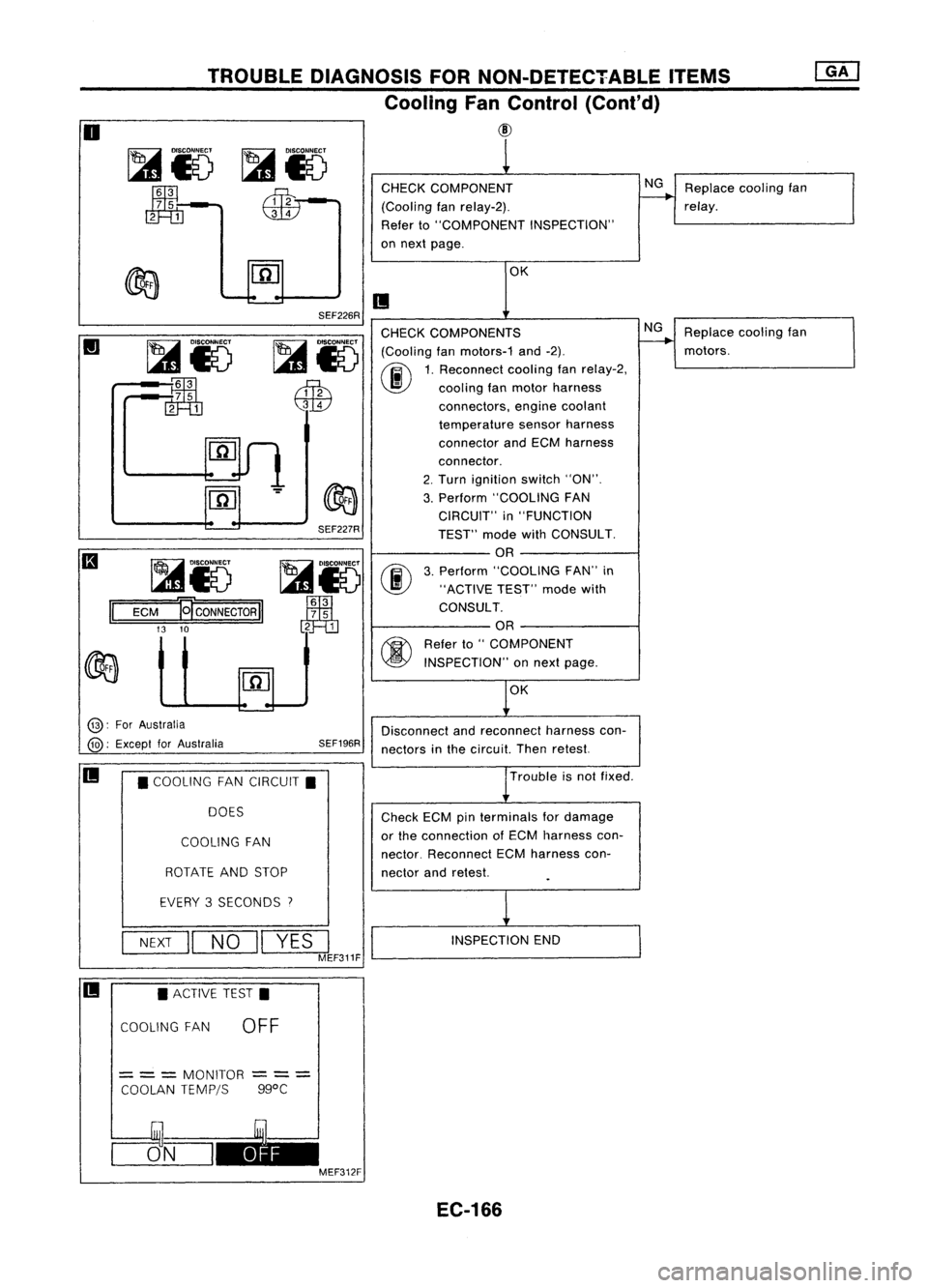
CHECK
COMPONENT
(Cooling fanrelay-2).
Refer to"COMPONENT INSPECTION"
on next page.
NG
Replace coolingfan
relay.
OK
II
Replacecoolingfan
motors.
NG
OK
SEF226R
SEF227R
~i5
00
Jm1
3
7 5
2 1
CHECK
COMPONENTS
~ IDlsco~
(Coolingfanmotors-1 and-2).
I...s1
0~
1.Rec~nnect coolingfanrelay-2,
~ \J!}
coolingfanmotor harness
QW
connectors,enginecoolant
temperature sensorharness
connector andECM harness
connector.
2. Turn ignition switch"ON".
3. Perform "COOLING FAN
CIRCUIT" in"FUNCTION
TEST" modewithCONSULT.
OR
3. Perform "COOLING FAN"in
"ACTIVE TEST"modewith
CONSULT.
OR
~ Referto"COMPONENT
~ INSPECTION" onnext page.
~i5
:~
rn=m
~i5
ECM
El'CONNECTORII
13 10
II
@:
ForAustralia
@:
Except forAustralia SEF196R
Disconnect
andreconnect harnesscon-
nectors inthe circuit. Thenretest.
II
•COOLING FANCIRCUIT.
DOES
COOLING FAN
ROTATE ANDSTOP
Trouble
isnot fixed .
Check ECMpinterminals fordamage
or the connection ofECM harness con-
nector. Reconnect ECMharness con-
nector andretest.
EVERY 3SECONDS
7
NEXT
II
NO
II
YES
I
MEF311F
INSPECTION
END
II •
ACTIVE TEST.
COOLING FAN
OFF
=
= =
MONITOR
COOLAN TEMPjS
---
---
ggoC
CJ5_N_I~ MEF312F
EC-166
Page 890 of 1701

•
INSPECTION END
OK
The
power steering oilpressure switchisattached tothe power
steering high-pressure tubeanddetects apower steering load.
When apower steering loadisdetected,
it
signals theECM. The
ECM adjusts theIACV-AAC valvetoincrease theidle speed and
adjust forthe increased load.
INSPECTION START
OR
1. Start engine.
2. Check voltage between ECM
terminal
@
or
@
and ground.
Voltage: When steering wheelis
turned quickly.
Approximately OV
Except above
Approximately 5V
NG
DIAGNOSTIC
PROCEDURE
CHECK OVERALL FUNCTION.
fiii\
1.Turn ignition switch"ON".
~ 2.Perform "PW/STSIGNAL
CIRCUIT" in"FUNCTION
TEST" modewithCONSULT.
OR
(F.i\
1.Start engine.
~ 2.Check "PW/ST SIGNAL" in
"DATA MONITOR" modewith
CONSULT.
Steering isin neutral
position: OFF
Steering isturned:
ON
SEF591I
SEF235R
MEF023E
Power
steering oil___
pressure switch
-
~
to
TROUBLE
DIAGNOSIS FORNON-DETECTABLE ITEMS
@[]
Power Steering OilPressure Switch(Cont'd)
COMPONENT DESCRIPTION
RECORD
NEXT
II
START
•
PW/ST SIGNAL CIRCUIT.
HOLD STEERING WHEEL
IN AFULL
LOCKED
POSITION
THEN
TOUCH START
* MONITOR *NO FAIL
0
PW/ST SIGNAL OFF
@):
ForAustralia
@:
Except forAustralia
~i)~
II
ECM
Ef
CONNECTOR
II
43 25
EC-171
Page 894 of 1701
•
Neutral
position switch
INSPECTION START
DIAGNOSTIC
PROCEDURE
SHIFT
OUT OFNIP-RANGETROUBLE
DIAGNOSIS FORNON-DETECTABLE ITEMS
@J
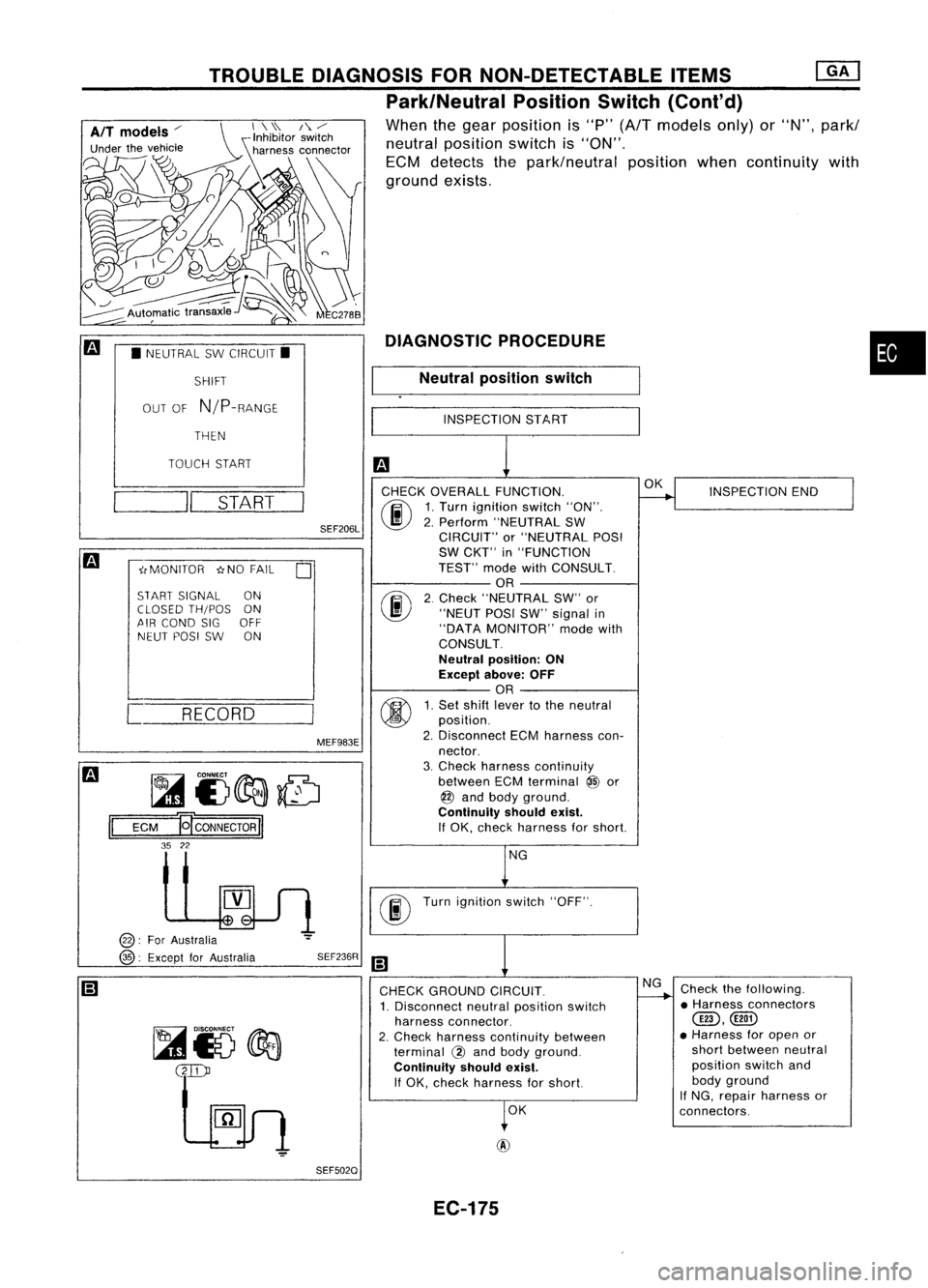
Park/Neutral PositionSwitch
(Cont'd)
When thegear position is"P"
(A/T
models only)or
"N",
parkl
neutral position switchis"ON",
ECM detects thepark/neutral positionwhencontinuity with
ground exists,
• NEUTRAL SWCIRCUIT.
THEN
TOUCH START
MEF983ESEF206L
~ CONNECT~
JA
L41E)~~
1=1
=E=CM~E CONNECTOR!'
35 22
INSPECTION
END
OK
Turn ignition switch"OFF".
NG
CHECK
OVERALL FUNCTION.
(ijJ\ 1.Turn ignition switch"ON".
~ 2.Perform "NEUTRAL SW
CIRCUIT" or"NEUTRAL POSI
SW CKT" in"FUNCTION
TEST" modewithCONSULT.
OR
rF.I\
2.Check "NEUTRAL SW"or
~ "NEUTPOSISW"signal in
"DATA MONITOR" modewith
CONSULT.
Neutral position: ON
Except above:OFF
OR
fff\
1.Set shift lever tothe neutral
~ position.
2. Disconnect ECMharness con-
nector.
3. Check harness continuity
between ECMterminal
@
or
@ and body ground.
Continuity shouldexist.
If OK, check harness forshort.
SEF236R
r:'I
.;,
i,MONITOR
*NOFAIL
0
START SIGNAL ON
CLOSED TH/POS ON
/lIR COND SIGOFF
NEUT POSISW ON
[ RECORD
@:
Fo'Australia
@:
Except forAustralia
__
II
START
CHECKGROUND CIRCUIT.
1. Disconnect neutralposition switch
harness connector.
2. Check harness continuity between
terminal @and body ground.
Continuity shouldexist.
If OK, check harness forshort.
OK NG
Check thefollowing.
• Harness connectors
@,(@)
• Harness foropen or
short between neutral
position switchand
body ground
If NG, repair harness or
connectors.
SEF5020 EC-175
Page 896 of 1701
TROUBLEDIAGNOSIS FORNON-DETECTABLE ITEMS
Park/Neutral PositionSwitch(Cont'd)
• PARKJNEUT POSISWCKT • Inhibitor
switch
MEF983E
I
NEXT
II__
ST:_A_RT __
I
MEC7318
•
INSPECTION
END
OK
INSPECTION
START
"N"
or
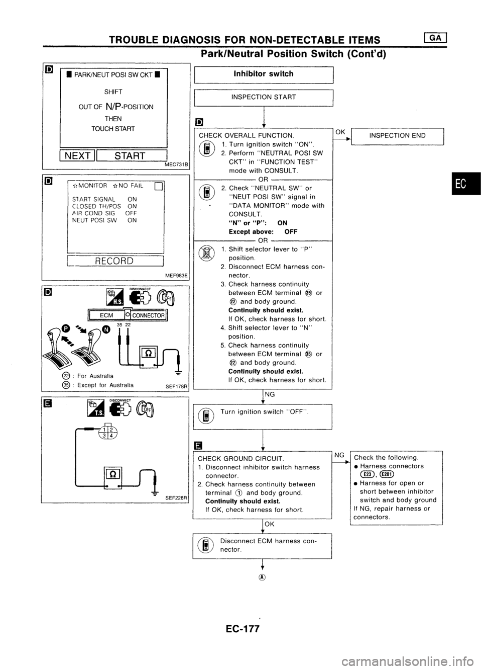
"P":
ON
Except above: OFF
OR
1. Shift selector leverto"P"
position.
2. Disconnect ECMharness con-
nector.
3. Check harness continuity
between ECMterminal
@
or
@ and body ground.
Continuity shouldexist.
If OK, check harness forshort
4. Shift selector leverto"N"
position.
5. Check harness continuity
between ECMterminal
@
or
@ and body ground.
Continuity shouldexist.
If OK, check harness forshort
1!1
CHECK OVERALL FUNCTION.
(ij\
1.Turn ignition switch"ON".
~ 2.Perform "NEUTRAL POSISW
CKT" in"FUNCTION TEST"
mode withCONSULT.
OR
rF.I\
2.Check "NEUTRAL SW"or
~ "NEUTPOSISW"signal in
"DATA MONITOR" modewith
CONSULT.
SEF178R
SHIFT
OUT OFNIP-POSITION
THEN
TOUCH START
~rMONITOR ~NOFAIL
0
SlART SIGNAL ON
CLOSED TH/POS ON
'!\IR COND SIGOFF
NEUT POSISW ON
[ RECORD
@ :
For Australia
@ :
Except forAustralia
~i5@a
II
ECM
19'
CONNECTOR
TI
G ...._ CD
3522
~~
~io@a
6iB
NG
Turn ignition switch"OFF"
SEF228R CHECK
GROUND CIRCUIT.
1. Disconnect inhibitorswitchharness
connector.
2. Check harness continuity between
terminal G)and body ground.
Continuity shouldexist.
If OK, check harness forshort. NG
Check thefollowing.
• Harness connectors
@D,@])
• Harness foropen or
short between inhibitor
switch andbody ground
If
NG, repair harness or
connectors.
OK
Disconnect ECMharness con-
nector.
EC-177
Page 898 of 1701
TROUBLEDIAGNOSIS FORNON-DETECTABLE ITEMS
EVAP Canister PurgeControl Solenoid Valve
GA16DE MITmodels exceptforEurope, Israeland
Australia
SYSTEM DESCRIPTION
Camshaft positionsensor
Engine coolant temperature sensor
Mass airflow sensor
Throttle positionsensor
Ignition switch
Vehicle speedsensor Engine
speed
Engine coolant temperature
Amount ofintake air
Throttle position
Start signal
Vehicle speed ECM
(ECCS
control
module) EVAP
canister
purge control
solenoid valve
•
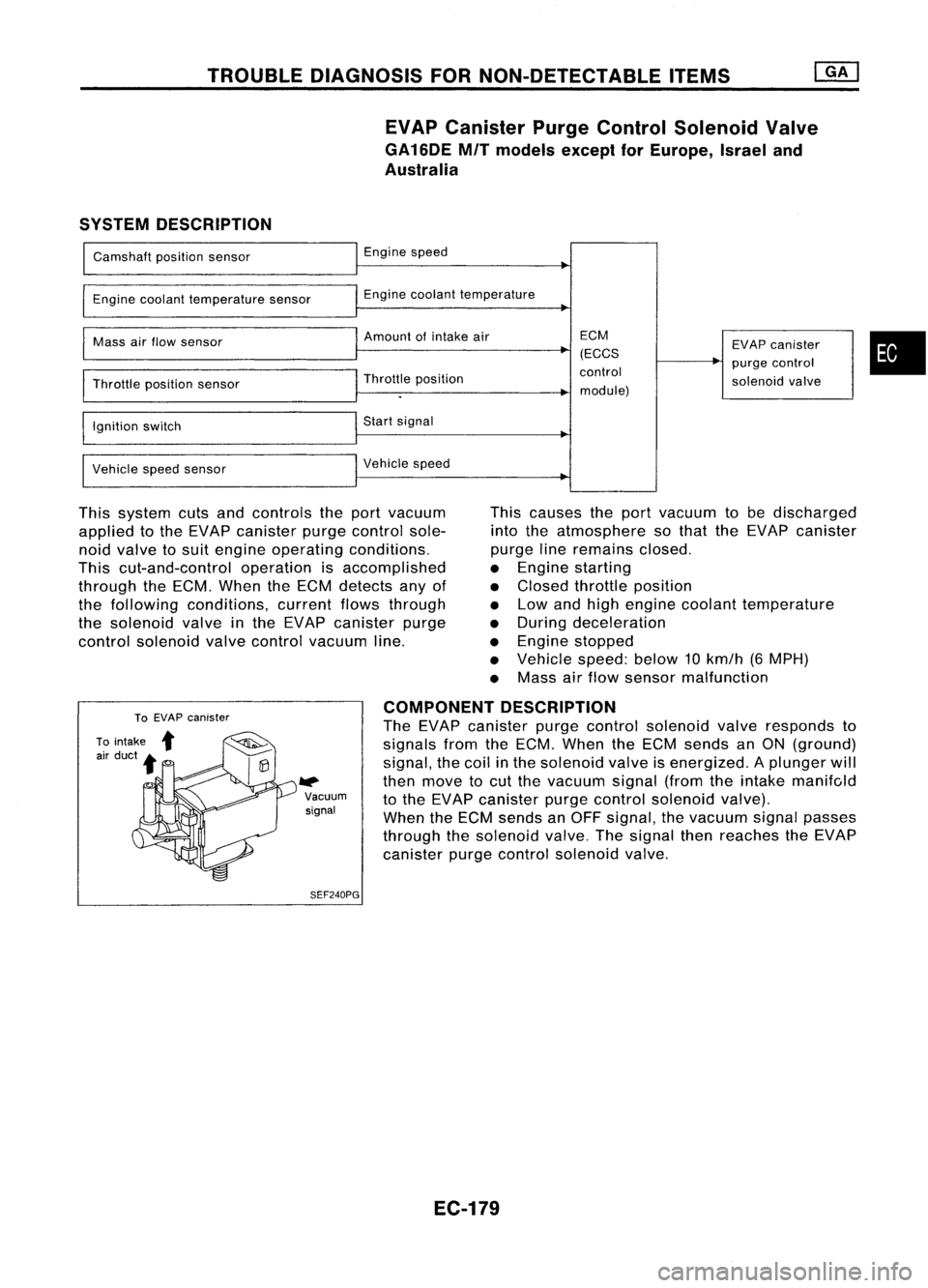
This system cutsandcontrols theport vacuum
applied tothe EVAP canister purgecontrol sole-
noid valve tosuit engine operating conditions.
This cut-and-control operationisaccomplished
through theECM. When theECM detects anyof
the following conditions, currentflowsthrough
the solenoid valveinthe EVAP canister purge
control solenoid valvecontrol vacuum line. This
causes theport vacuum tobe discharged
into theatmosphere sothat theEVAP canister
purge lineremains closed.
• Engine starting
• Closed throttle position
• Low andhigh engine coolant temperature
• During deceleration
• Engine stopped
• Vehicle speed:below10km/h (6MPH)
• Mass airflow sensor malfunction
W>
Vacuum
signal
SEF240PG COMPONENT
DESCRIPTION
The EVAP canister purgecontrol solenoid valveresponds to
signals fromtheECM. When theECM sends anON (ground)
signal, thecoil inthe solenoid valveisenergized. Aplunger will
then move tocut the vacuum signal(fromtheintake manifc,ld
to the EVAP canister purgecontrol solenoid valve).
When theECM sends anOFF signal, thevacuum signalpasses
through thesolenoid valve.Thesignal thenreaches theEVAP
canister purgecontrol solenoid valve.
EC-179