Page 802 of 1701
![NISSAN ALMERA N15 1995 Service Manual TROUBLEDIAGNOSES -General Description @K]
ECM Terminals andReference Value(Conl'd)
ECM INSPECTION TABLE-Except GA16DE forAustralia
Specification dataarereference valuesandaremeasured betweeneacht NISSAN ALMERA N15 1995 Service Manual TROUBLEDIAGNOSES -General Description @K]
ECM Terminals andReference Value(Conl'd)
ECM INSPECTION TABLE-Except GA16DE forAustralia
Specification dataarereference valuesandaremeasured betweeneacht](/manual-img/5/57349/w960_57349-801.png)
TROUBLEDIAGNOSES -General Description @K]
ECM Terminals andReference Value(Conl'd)
ECM INSPECTION TABLE-Except GA16DE forAustralia
Specification dataarereference valuesandaremeasured betweeneachterminal and
@
(ECCS ground).
TERMINAL WIRE
NO. COLOR ITEM
CONDITION DATA
IEngine isrunning.1
0.2-0.3V
L
Idle speed
1
WIB
Ignitionsignal
IEngineisru~
L
Engine speedis2,000 rpm. Approximately
0.7V
Tachometer IEngineisrunning.1
2 LIB
(Modelswithtachome-
L
Idle speed 0.7
-0.9V
ter)
3 GYIR
Ignitioncheck jEngine
isrunning.1
Approximately13V
L
Idle speed
Engine isrunning.'
I
Ignition switch"OFF"I
0-1V
ECCS relay(Self-shut-
L
For afew seconds afterturning ignition
4
WIG
off) switch
"OFF"
llgnition switch"OFF"I
BATTERYVOLTAGE
L
Afew seconds afterturning ignition
(11-14V)
switch "OFF"andthereafter
IEngine isrunning.1
BATTERYVOLTAGE
Cooling fanrelay (Low
L
Cooling fanisnot operating. (11-14V)
9 LGIR
speed) IEngineisrunning.1
L
Cooling fanisoperating. Approximately
OV
IEngine isrunning.1
BATTERYVOLTAGE
Cooling fanrelay (High
t
Cooling fanisnot operating.
(11-14V)
10 LG Cooling
fanisoperating atlow speed.
speed) IEngineisrunning.1
L
Cooling fanisoperating athigh speed. Approximately
OV
IEngine isrunning.1
L
Both
AIC
switch andblower fanswitch Approximately
OV
11 Yor
GAir
conditioner relay are
"ON".
IEngine isrunning.1
BATTERYVOLTAGE
LAIC
switchis"OFF". (11
-14V)
IEngine isrunning.1
BATTERYVOLTAGE
VTC solenoid valve
L
Idle speed (11
-14V)
12 YIR (GA
16DE engine mod-
IEngineisrunning.1
els except forEurope
and Israel)
L
Engine isracing quickly fromidleto4,000 Approximately
OV
rpm at1st position.
EC-83
•
Page 805 of 1701
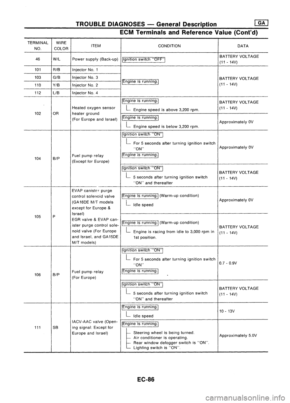
TROUBLEDIAGNOSES -General Description
mJ
ECM Terminals andReference Value(Cont'd)
TERMINAL WIRE
NO. COLOR ITEM
CONDITION DATA
46 WIL Powersupply (Back-up)
Ilgnitionswitch"OFF'" BA
TTERY VOLTAGE
(11 -14V)
101 RIB InjectorNo.1
103
GIB
InjectorNo.3
BATTERYVOLTAGE
110 Y/B InjectorNO.2 IEngine
isrunning./
(11-14V)
112 LIB Injector
NO.4
IEngineisrunning.1
BATTERY VOLTAGE
Heated oxygen sensor
L
Engine speedisabove 3,200rpm. (11
-14V)
102 OR heaterground
(For Europe andIsrael) IEngine
isrunning.1
ApproximatelyOV
L
Engine speedisbelow 3,200rpm.
jlgnition switch"ON"I
L
For 5seconds afterturning ignition switch
"ON" Approximately
OV
104 B/P Fuel
pump relay /Engine
isrunning.1
(Except forEurope)
Ilgnitionswitch"ON"I
BATTERYVOLTAGE
L
5seconds afterturning ignition switch
(11-14V)
"ON" andthereafter
EVAP canister purge
control solenoid valveIEngine
isrunning.1 (Warm-up condition)
(GA16DE
MIT
models
L
Idle speed Approximately
OV
except forEurope
&
105 P Israel)
EGR valve
&
EVAP can-
ister purge control sole-IEngine
isrunning.1 (Warm-up condition)
BATTERYVOLTAGE
noid valve (ForEurope
L
Engine isracing fromidleto3,000 rpmin
(11-14V)
and Israel, andGA15DE
1st position.
MIT
models)
jlgnitionswitch"ON"I
L
For 5seconds afterturning ignition switch
"ON" 0.7
-0.9V
106 SIP Fuel
pump relay IEngine
isrunning.1
(For Europe)
-
Ilgnition switch"ON"I
BATTERYVOLTAGE
L
5seconds afterturning ignition switch
(11-14V)
"ON" andthereafter
IEngine isrunning.1
10-13V
L
Idle speed
IACV-AAC valve(Open-
IEngineisrunning.1
111 5B ingsignal: Exceptfor
Europe andIsrael)
l
51.."" wheel
t,
be'" I,med
Approximately5.0V
Air conditioner isoperating.
Rear window defogger switchis"ON".
Lighting switchis"ON".
EC-86
Page 814 of 1701
TROUBLEDIAGNOSIS FORDTC11 @KJ
Camshaft PositionSensor(CMPS) (Cont'd)
DIAGNOSTIC TROUBLECODECONFIRMATION
PROCEDURE
fiii\
1)Turn ignition switch"ON"andselect "DATA
\JV
MONITOR" modewithCONSULT.
2) Crank engine foratleast 2seconds.
---------- OR-----------
~ 1)Crank engine foratleast 2seconds.
~ 2)Turn ignition switch"OFF", waitforatleast 5seconds
and then turn"ON".
3) Perform "Diagnostic TestMode II"(Self-diagnostic
results) withECM.
EC-95
•
Page 820 of 1701
TROUBLEDIAGNOSIS FORDTC12
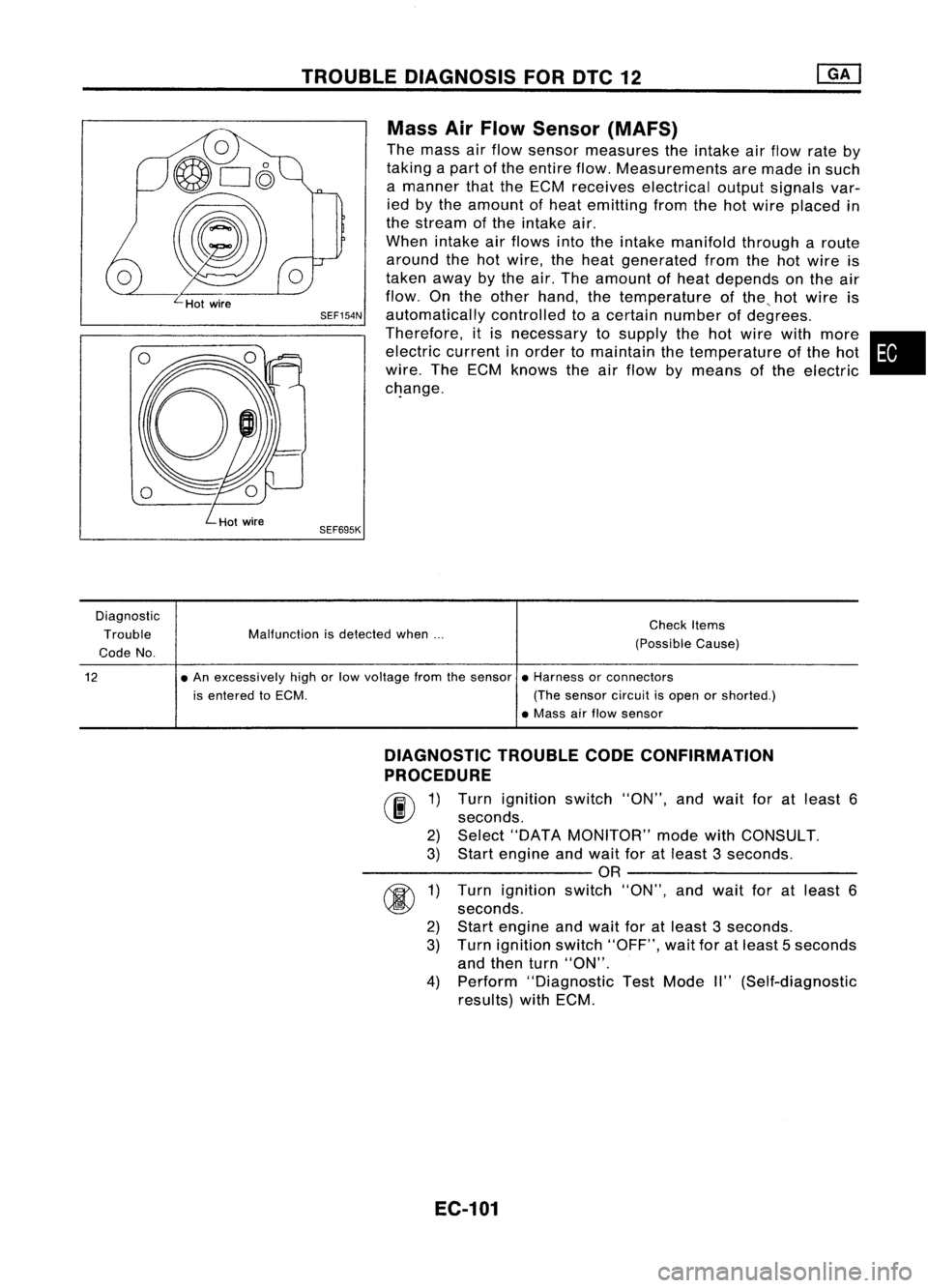
Mass AirFlow Sensor (MAFS)
The mass airflow sensor measures theintake airflow rateby
taking apart ofthe entire flow.Measurements aremade insuch
a manner thattheECM receives electrical outputsignals var-
ied bythe amount ofheat emitting fromthehotwire placed in
the stream ofthe intake air.
When intake airflows intotheintake manifold througharoute
around thehotwire, theheat generated fromthehotwire is
taken awaybythe air.The amount ofheat depends onthe air
flow. Onthe other hand, thetemperature ofthe ..hot wire is
SEF154N
automatically controlledtoacertain number ofdegrees.
Therefore, itis necessary tosupply thehotwire withmore •
electric currentinorder tomaintain thetemperature ofthe hot
wire. TheECM knows theairflow bymeans ofthe electric
c~ange.
SEF695K
Diagnostic Trouble
Code No. Malfunction
isdetected when... Check
Items
(Possible Cause)
12
•
An excessively highorlow voltage fromthesensor •Harness orconnectors
is entered toECM. (Thesensor circuitisopen orshorted.)
• Mass airflow sensor
DIAGNOSTIC TROUBLECODECONFIRMATION
PROCEDURE
rif\
1)Turn ignition switch"ON",andwait foratleast 6
~ seconds.
2) Select "DATA MONITOR" modewithCONSULT.
3) Start engine andwait foratleast 3seconds.
----------OR ----------
r
1)Turn ignition switch"ON",andwait foratleast 6
~ seconds.
2) Start engine andwait foratleast 3seconds.
3) Turn ignition switch"OFF", waitforatleast 5seconds
and then turn"ON".
4) Perform "Diagnostic TestMode II"(Self-diagnostic
results) withECM.
EC-101
Page 824 of 1701
•
Repair
harness orcon-
nectors.
Repair harness orcon-
nectors.
Replace massairflow
sensor. Repair
harness orcon-
nectors.
NG
NG
NG
NG
INSPECTION
START
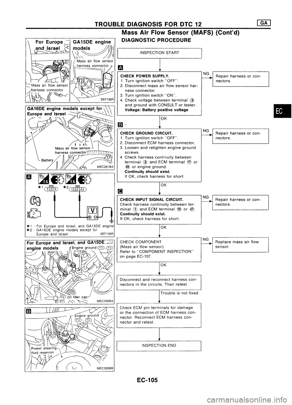
CHECK POWER SUPPLY.
1. Turn ignition switch"OFF".
2. Disconnect massairflow sensor har-
ness connector.
3. Turn ignition switch"ON".
4. Check voltage between terminal
@
and ground withCONSULT ortester.
Voltage: Batterypositive voltage
CHECK INPUTSIGNAL CIRCUIT.
Check harness continuity betweenter-
minal
CD
and ECM terminal
@
or@.
Continuity shouldexist.
If OK, check harness forshort.
INSPECTION END
OK
Trouble isnot fixed.
CHECK
GROUND CIRCUIT.
1. Turn ignition switch"OFF".
2. Disconnect ECMharness connector.
3. Loosen andretighten engineground
screws.
4. Check harness continuity between
terminal
@
and ECM terminal
@
or
@
orengine ground.
Continuity shouldexist.
If OK, check harness forshort.
CHECK COMPONENT
(Mass airflow sensor).
Refer to"COMPONENT INSPECTION"
on page EC-107.
Disconnect andreconnect harnesscon-
nectors inthe circuits. Thenretest.
Check ECMpinterminals fordamage
or the connection ofECM harness con-
nector. Reconnect ECMharness con-
nector andretest.
SEF138R
TROUBLE
DIAGNOSIS FORDTC12
Mass AirFlow Sensor (MAFS) (Conl'd)
DIAGNOSTIC PROCEDURE
For Europe ~GA 15DE engine
and Israel
I~
",,~~)rl
\~\" /JJ~
11'
Mass airflow sensor
_ harness connector
==---,
I-
I
I
d.-
I
;~
*1 ForEurope andIsrael, andGA15DE engine
*2 :GA 16DE engine models exceptfor
Europe andIsrael SEF139R
~
Mass airflow sensor
~(~lr~~
,~\ C/
Power steering \'
tluic! reservxr ..--\ /,'"
W~
Meo,"""
EC-105
Page 827 of 1701
TROUBLEDIAGNOSIS FORDTC13
SEF594K Engine
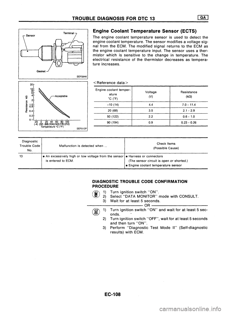
Coolant Temperature Sensor(ECTS)
The engine coolant temperature sensorisused todetect the
engine coolant temperature. Thesensor modifies avoltage sig-
nal from theECM. Themodified signalreturns tothe ECM as
the engine coolant temperature input.Thesensor usesather-
mistor whichissensitive tothe change intemperature. The
electrical resistance ofthe thermistor decreases astempera-
ture increases.
20
18
6
9 4
B
2
Iii
10
1ii
0.8
'0
£ 0.4
0.2
0.1 -20 020 40 60 80100
(-4) (32) (68)(104)(140)(176)(212)
Temperature 'C
(OF)
SEF012P
<
Reference data>
Engine coolant temper-
Voltage Resistance
ature
'C ('F) (V)
(kQ)
-10 (14) 4.47.0-11.4
20 (68)
3.52.1-2.9
50 (122)
2.20.6-1.0
90 (194) 0.9
0.23-0.26
Diagnostic
Trouble Code
No.
Malfunction
isdetected when... Check
Items
(Possible Cause)
13
•An excessively highorlow voltage fromthesensor •Harness orconnectors
is entered toECM. (Thesensor circuitisopen orshorted.)
• Engine coolant temperature sensor
DIAGNOSTIC TROUBLECODECONFIRMATION
PROCEDURE
(F.i\
1)Turn ignition switch"ON".
~ 2)Select "DATA MONITOR" modewithCONSULT.
3) Wait foratleast 5seconds.
------------OR------------
fU\
1)Turn ignition switch"ON"andwait foratleast 5sec-
~ onds.
2) Turn ignition switch"OFF", waitforatleast 5seconds
and then turn"ON".
3) Perform "Diagnostic TestMode II"(Self-diagnostic
reSUlts) withECM.
EC-108
Page 832 of 1701
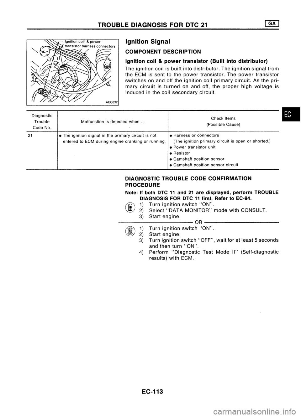
TROUBLEDIAGNOSIS FORDTC21
Malfunction isdetected when...
Diagnostic
Trouble
Code No.
Ignition
coil
&
power
transistor harnessconnectors
AEC832 Ignition
Signal
COMPONENT DESCRIPTION
Ignition coil
&
power transistor (Builtintodistributor)
The ignition coilisbuilt intodistributor. Theignition signalfrom
the ECM issent tothe power transistor. Thepower transistor
switches onand offthe ignition coilprimary circuit.Asthe pri-
mary circuit isturned onand off,the proper highvoltage is
induced inthe coil secondary circuit.
Check Items
(Possible Cause)
•
21
•
The ignition signalinthe primary circuitisnot
entered toECM during engine cranking orrunning. •
Harness orconnectors
(The ignition primary circuitisopen orshorted.)
• Power transistor unit.
• Resistor
• Camshaft positionsensor
• Camshaft positionsensorcircuit
DIAGNOSTIC TROUBLECODECONFIRMATION
PROCEDURE
Note: Ifboth DTC11and 21are displayed, performTROUBLE
DIAGNOSIS FORDTC11first. Refer toEC-94.
(F.i\ 1)Turn ignition switch"ON".
~ 2)Select "DATA MONITOR" modewithCONSULT.
3) Start engine.
----------OR ----------
1) Turn ignition switch"ON".
2) Start engine.
3) Turn ignition switch"OFF", waitforatleast 5seconds
and then turn"ON".
4) Perform "Diagnostic TestMode II"(Self-diagnostic
results) withECM.
EC-113
Page 838 of 1701
TROUBLEDIAGNOSIS FOROTC34
PIEZO-ELEMENT Malfunction isdetected when....
Diagnostic
Trouble Code
No. SEF598KKnock
Sensor (KS)
The knock sensor isattached tothe cylinder block.Itsenses
engine knocking usingapiezoelectric element.Aknocking
vibration fromthecylinder blockissensed asvibrational pres-
sure. Thispressure isconverted intoavoltage signalandsent
to the ECM.
CheckItems
(Possible Cause)
•
00
1)
2)
3)
34
•An excessively loworhigh voltage fromtheknock •Harness orconnectors
sensor isentered toECM. (Theknock sensor circuitisopen orshorted.)
• Knock sensor
DIAGNOSTIC TROUBLECODECONFIRMATION
PROCEDURE
rif\
1)Turn ignition switch"ON"andselect "DATA
\J!I)
MONITOR" modewithCONSULT.
2) Start engine andrunitfor atleast 5seconds atidle
speed.
---------- OR----------
Start engine andrunitfor atleast 5seconds atidle
speed.
Turn ignition switch"OFF", waitforatleast 5seconds
and then turn"ON".
Perform "Diagnostic TestMode II"(Self-diagnostic
results) withECM.
EC-119