Page 333 of 1701
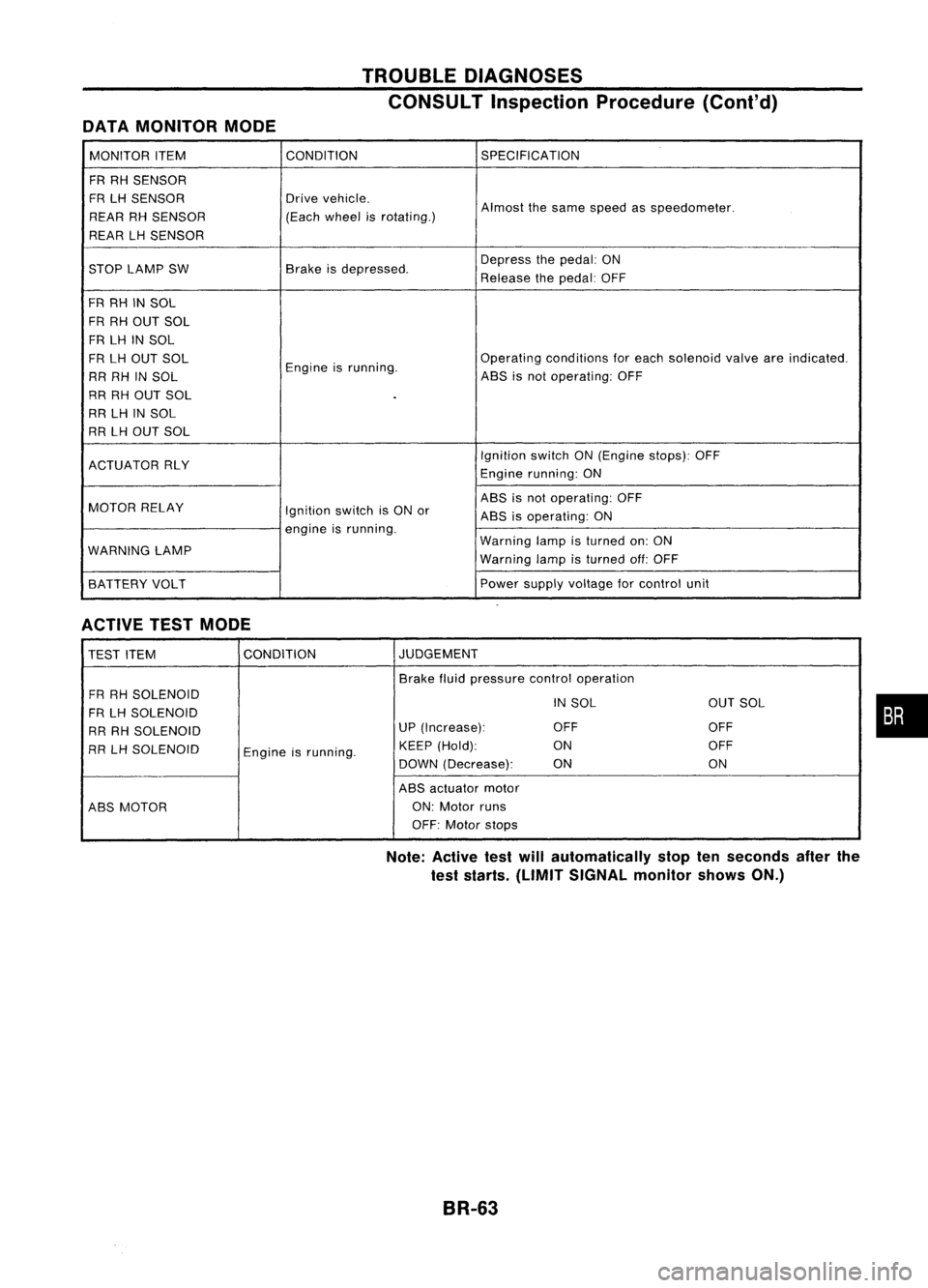
DATAMONITOR MODE TROUBLE
DIAGNOSES
CONSULT Inspection Procedure(Cont'd)
MONITOR ITEM CONDITION
SPECIFICATION
FR RH SENSOR
FR LHSENSOR Drive
vehicle.
Almostthesame speed asspeedometer.
REAR RHSENSOR (Each
wheel isrotating.)
REAR LHSENSOR
STOP LAMP SW Brake
isdepressed. Depress
thepedal: ON
Release thepedal: OFF
FR RH INSOL
FR RH OUT SOL
FR LH INSOL
FR LH OUT SOL
Engineisrunning. Operating
conditions foreach solenoid valveareindicated.
RR RH INSOL ABS
isnot operating: OFF
RR RH OUT SOL
.
RR LHINSOL
RR LHOUT SOL
IgnitionswitchON(Engine stops):OFF
ACTUATOR RLY
Enginerunning: ON
MOTOR RELAY ABS
isnot operating: OFF
Ignition switchisON or
ABSisoperating: ON
engine isrunning.
WARNING LAMP Warning
lampisturned on:ON
Warning lampisturned off:OFF
BATTERY VOLT Power
supply voltage forcontrol unit
ACTIVE TESTMODE
TEST ITEM CONDITION JUDGEMENT
Brake fluidpressure controloperation
FR RH SOLENOID
INSOL OUTSOL
FR LH SOLENOID
RR RH SOLENOID UP
(Increase): OFF OFF
RR LHSOLENOID
Engineisrunning. KEEP
(Hold): ON OFF
DOWN (Decrease): ON ON
ABS actuator motor
ABS MOTOR ON:
Motor runs
OFF: Motor stops
Note: Active testwillautomatically stoptenseconds afterthe
test starts. (LIMIT SIGNAL monitorshowsON.)
BR-63
•
Page 356 of 1701
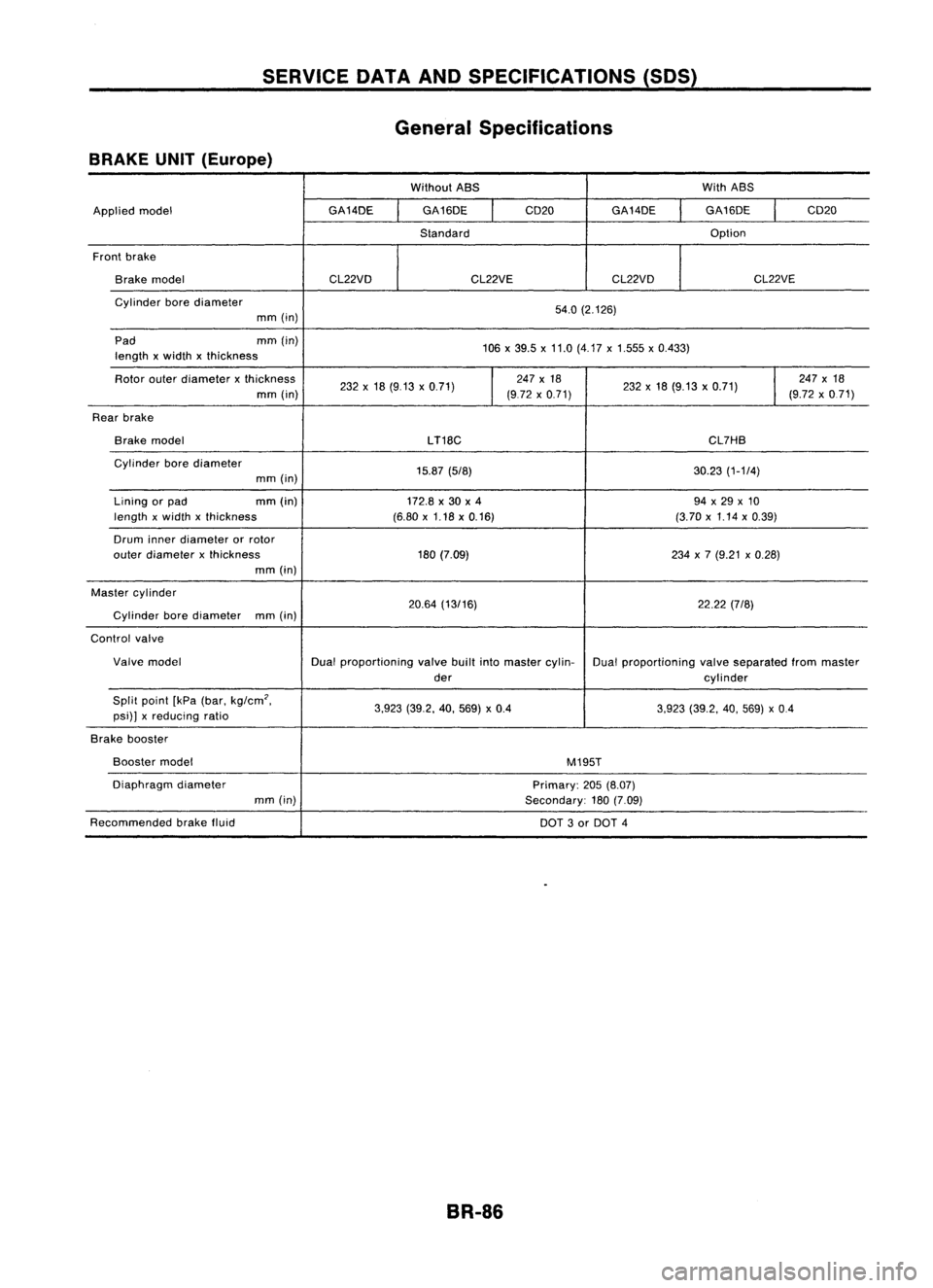
SERVICEDATAANDSPECIFICATIONS (SOS)
General Specifications
BRAKE UNIT(Europe)
WithoutABS WithABS
Applied model GA14DE
GA16DE
I
CD20
GA14DE GA16DE
I
CD20
Standard Option
Front brake
Brake model CL22VDCL22VECL22VD CL22VE
Cylinder borediameter
54.0(2.126)
mm (in)
Pad mm(in)
106x39.5 x11.0 (4.17 x1.555 x0.433)
length xwidth xthickness
Rotor outerdiameter xthickness
232x18 (9.13 x0.71)
I
247
x18
232x18 (9.13 x0.71)
I
247
x18
mm (in) (972x0.71) (9.72x0.71)
Rear brake
Brake model
LT18C CL7HB
Cylinder borediameter
15.87(5/8) 30.23(1-1/4)
mm (in)
Lining orpad mm
(in)
172.8x30 x4 94x29 x10
length xwidth xthickness (6.80x1.18 x0.16) (3.70x1.14 x0.39)
Drum innerdiameter orrotor
outer diameter xthickness 180(7.09) 234x7 (9.21 x0.28)
mm (in)
Master cylinder
20.64(13/16) 22.22(7/8)
Cylinder borediameter
mm(in)
Control valve
Valve model Dualproportioning valvebuiltintomaster cylin-
Dualproportioning valveseparated frommaster
der cylinder
Split point [kPa(bar. kg/cm
2•
3.923(39.2. 40.569) x0.4
3.923(39.2. 40.569) x0.4
psi)] xreducing ratio
Brake booster
Booster model
M195T
Diaphragm diameter
Primary:205(8.07)
mm (in)
Secondary:180(7.09)
Recommended brakefluid
DOT3or DOT 4
BR-86
Page 357 of 1701
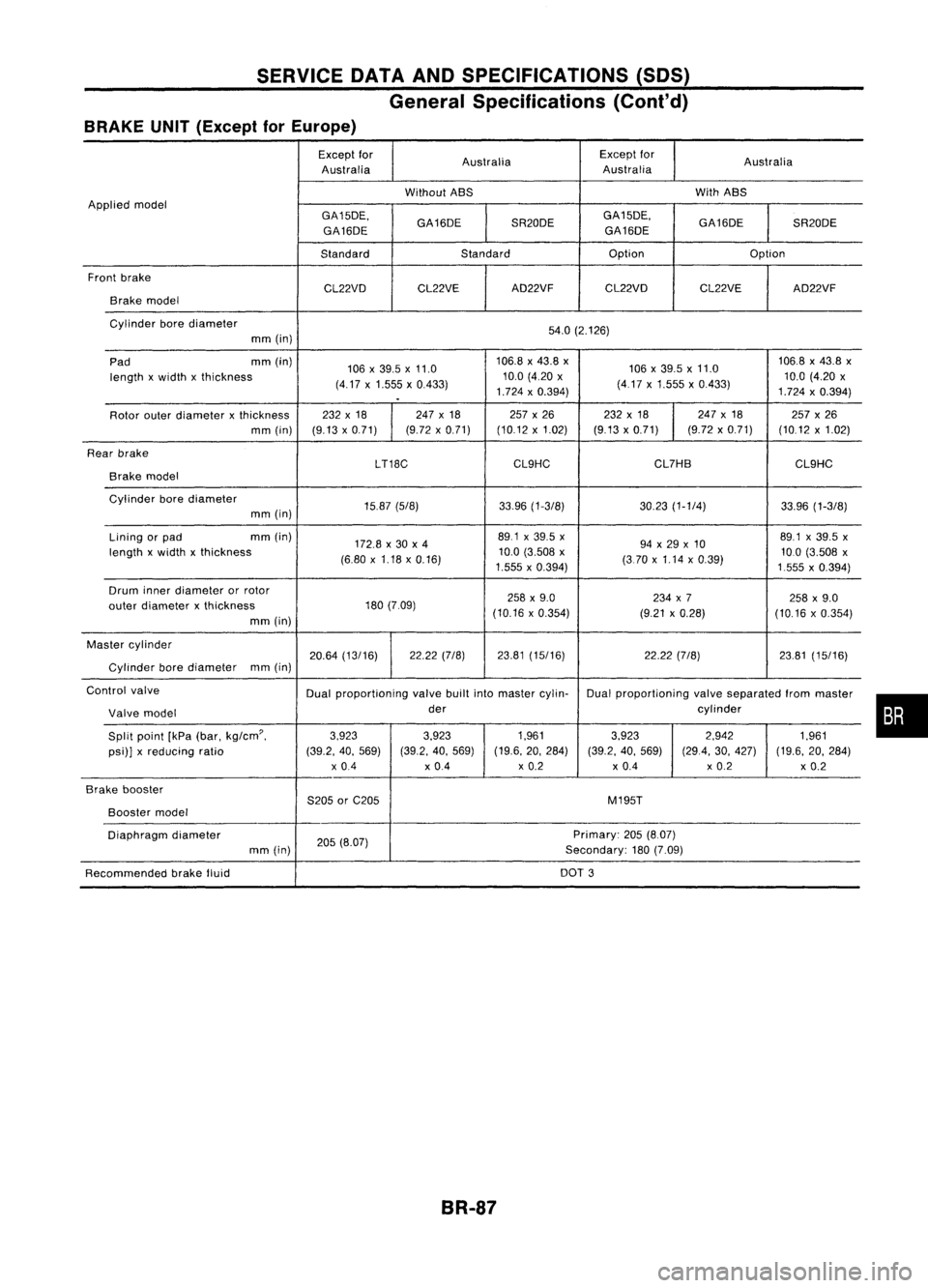
SERVICEDATAANDSPECIFICATIONS (SDS)
General Specifications (Cont'd)
BRAKE UNIT(Except forEurope)
Except for
Australia Except
for
Australia
Australia Australia
Without ABS With
ABS
Applied model
GA15DE.GA16DESR20DEGA15DE.
GA16DESR20DE
GA16DE GA16DE
Standard Standard Option
Option
Front brake
CL22VDCL22VE AD22VF
CL22VD CL22VEAD22VF
Brake model
Cylinder borediameter
54.0(2.126)
mm (in)
Pad mm
(in)
106x39.5 x11.0 106.8
x43.8 x
106x39.5x11.0 106.8
x43.8 x
length xwidth xthickness
(4.17x1.555 x0.433) 10.0
(4.20 x
(417x1.555 x0.433) 10.0
(4.20 x
.
1.724
x0.394)
1.724x0.394)
Rotor outerdiameter xthickness 232
x18 247x18 257x26 232x18 247
x18
257x26
mm (in) (9.13x0.71) (9.72
x0.71) (10.12x1.02) (9.13x0.71) (9.72x0.71) (10.12x1.02)
Rear brake
LT18CCL9HC CL7HB
CL9HC
Brake model
Cylinder borediameter
15.87(5/8) 33.96(1-3/8) 30.23(1-1/4) 33.96(1-3/8)
mm (in)
Lining orpad mm
(in)
172.8x30 x4 89.1
x39.5 x
94x29 x10 89.1
x39.5 x
length xwidth xthickness
(6.80x1.18 x0.16) 10.0
(3.508 x
(370x1.14 x0.39) 10.0
(3.508 x
1.555 x0.394)
1555x0.394)
Drum innerdiameter orrotor
258x9.0 234x7
258x9.0
outer diameter xthickness 180
(7.09)
(10.16x0.354) (9.21x0.28)
(10.16x0.354)
mm (in)
Master cylinder
20.64(13/16) 22.22
(7/8) 23.81(15/16) 22.22(7/8) 23.81(15/16)
Cylinder borediameter mm
(in)
Control valve
Dualproportioning valvebuiltintomaster cylin- Dualproportioning valveseparated frommaster
Valve model der
cylinder
Split point [kPa(bar.
kg/cm'.
3.923
3.923 1.9613.923 2.942
1.961
psi)] xreducing ratio (39.2.40.569) (39.2.40.569) (19.6.
20.284)
(39.2.40.569) (29.4.30.427) (19.6.20.284)
x 0.4 x0.4 x
0.2
x0.4 x
0.2
x0.2
Brake booster
S205orC205 M195T
Booster
model
Diaphragm diameter
205(8.07) Primary:
205(8.07)
mm (in) Secondary:180(7.09)
Recommended brakefluid DOT
3
BR-87
•
Page 358 of 1701
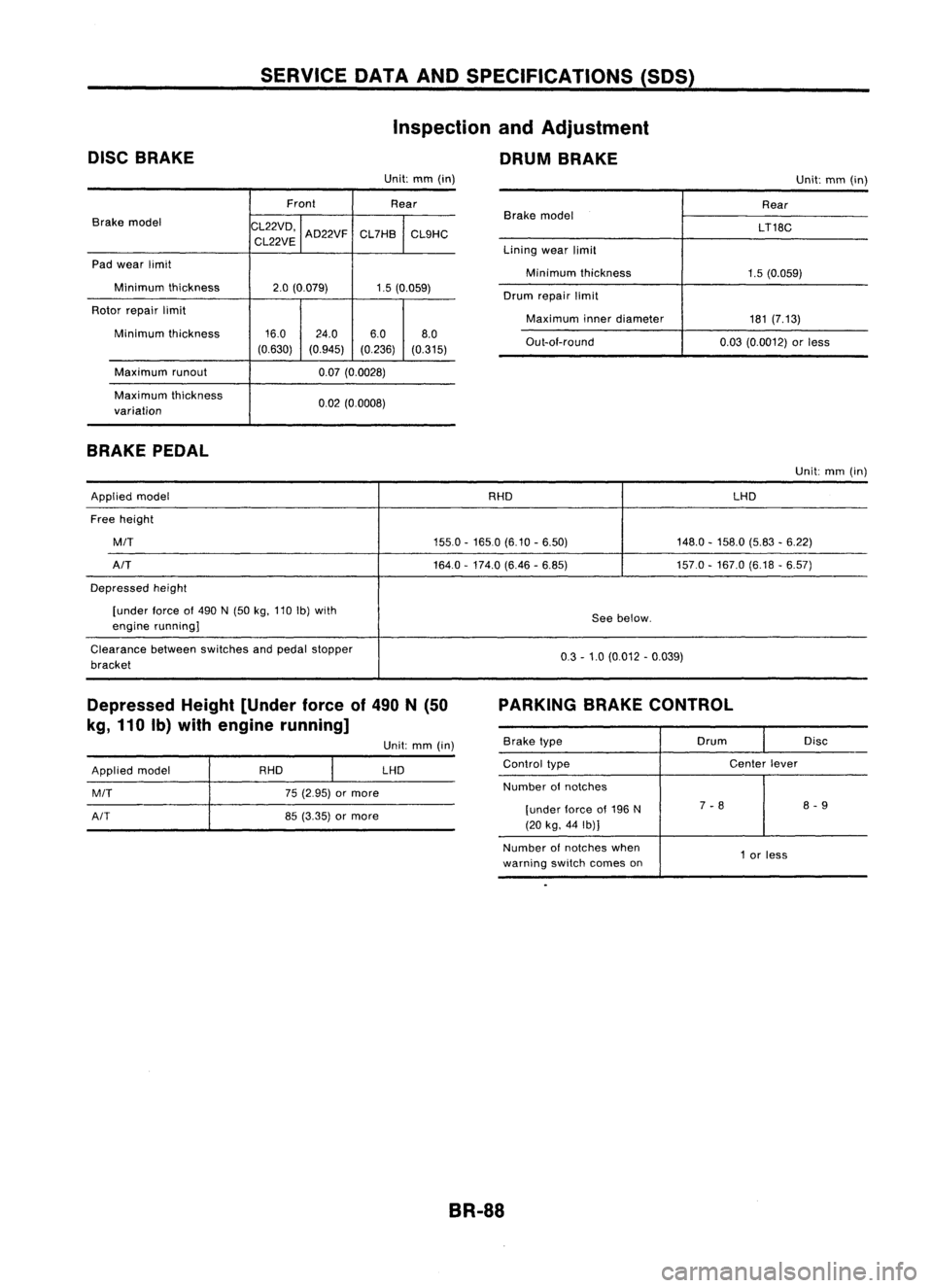
DISCBRAKE SERVICE
DATAANDSPECIFICATIONS (SDS)
Inspection andAdjustment
DRUM BRAKE
Unit: mm(in)
Unit:mm(in)
Front Rear
Brake model
CL22VD,
CL22VE AD22VF
CL7HB
CL9HC
Pad wear limit
Minimum thickness
2.0(0.079) 1.5(0.059)
Rotor repair limit
Minimum thickness 16.0
24.0 6.08.0
(0.630) (0.945) (0.236)(0.315)
Maximum runout 0.07(0.0028)
Maximum thickness
0.02(0.0008)
variation
BRAKE PEDAL
Brake
model
Lining wearlimit
Minimum thickness
Drum repair limit
Maximum innerdiameter
Out-ai-round Rear
LT18C
1.5 (0.059)
181 (7.13)
0.03 (0.0012) orless
Unit: mm(in)
Applied model RHDLHD
Free height
MIT
155.0-1650 (6.10-6.50) 148.0-158.0 (5.83-6.22)
AIT
164.0-174.0 (6.46-6.85) 157.0-167.0 (6.18-6.57)
Depressed height
[under force
01
490 N(50 kg,110 Ib)with
Seebelow.
engine running]
Clearance betweenswitches andpedal stopper
0.3-1.0 (0.012 -0.039)
bracket
Depressed Height[Under forceof490 N(50
kg, 110 Ib)with engine running] PARKING
BRAKECONTROL
Applied model
MIT
AIT
RHD
75(2.95) ormore
85 (3.35) ormore Unit:
mm(in)
LHD
Brake
type Drum
Disc
Control type Center
lever
Number
01
notches
[under lorceof196 N 7
-8 8
-9
(20 kg, 44Ib)]
Number ofnotches when
1or less
warning switchcomes on
BR-88
Page 363 of 1701
INSPECTIONANDADJUSTMENT
Pedal stopper
Dash lower
panel (except
CD20 engine //
model)
/L
Floor car-pet
L
Dash reinforcement panel
(CD20 engine model)
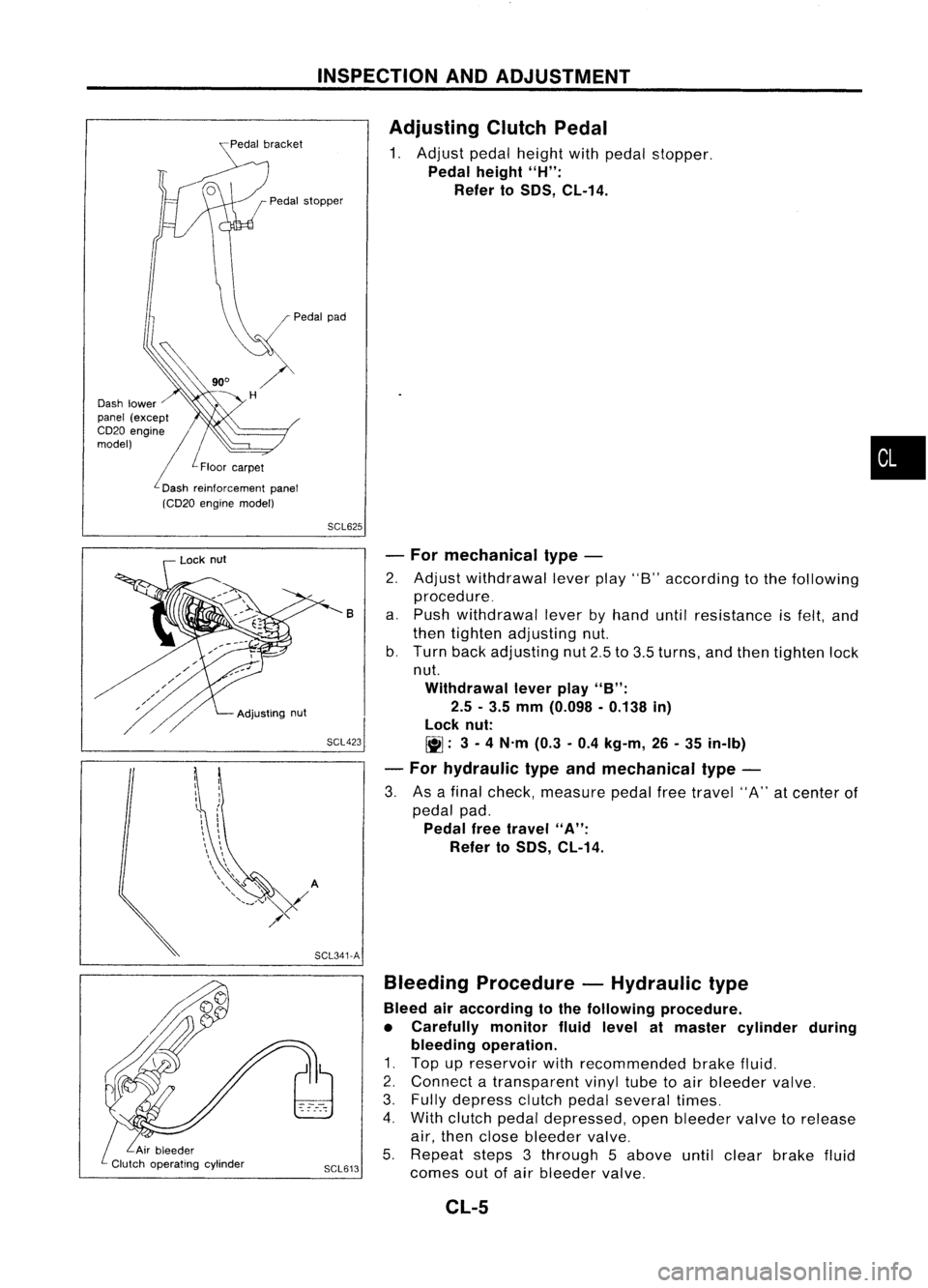
Adjusting
ClutchPedal
1. Adjust pedalheight withpedal stopper.
Pedal height
"H":
Refer to
50S,
CL-14.
•
SCL625
SCL423 -
For mechanical type-
2. Adjust withdrawal leverplay"8"according tothe following
procedure_
a. Push withdrawal leverbyhand untilresistance isfelt, and
then tighten adjusting nut.
b. Turn backadjusting nut2.5to3.5 turns, andthen tighten lock
nut.
Withdrawal leverplay
"B":
2.5 -3.5 mm (0.098 -0.138 in)
lock nut:
~: 3-
4 N'm (0.3-0.4 kg-m, 26-35 in-Ib)
- For hydraulic typeandmechanical type-
3. Asafinal check, measure pedalfreetravel "A"atcenter of
pedal pad.
Pedal freetravel
"A":
Refer to
50S,
CL-14.
B
Bleeding Procedure -Hydraulic type
Bleed airaccording tothe following procedure.
• Carefully monitorfluidlevel atmaster cylinder during
bleeding operation.
1. Top upreservoir withrecommended brakefluid.
2. Connect atransparent vinyltubetoair bleeder valve.
3. Fully depress clutchpedalseveral times.
4. With clutch pedaldepressed, openbleeder valvetorelease
air, then close bleeder valve.
5. Repeat steps3through 5above untilclear brake fluid
SCL613
comesoutofair bleeder valve.
SCL341-A
Adjusting
nut
Lock
nut
CL-5
Page 370 of 1701
CLUTCHDISCANDCLUTCH COVER
Clutch Disc(Cont'd)
INSTALLATION
• Apply recommended greasetocontact surface ofsplines.
• Too much lubricant maydamage clutchdiscfacing.
Dial gauge Clutch
CoverandFlywheel
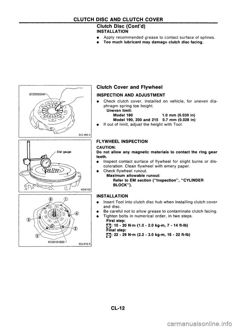
INSPECTION ANDADJUSTMENT
• Check clutchcover, installed onvehicle, foruneven dia-
phragm springtoeheight.
Uneven limit:
Model 180 1.0mm (0.039 in)
Model 190,
200and 215 0.7mm (0.028 in)
• Ifout oflimit, adjust theheight withTool.
SCL466-A FLYWHEEL INSPECTION
CAUTION:
Do not allow anymagnetic materials tocontact thering gear
teeth.
• Inspect contact surface offlywheel forslight burns ordis-
coloration. Cleanflywheel withemery paper.
• Check flywheel runout.
Maximum allowable runout:
Refer toEM section ("Inspection", "CYLINDER
BLOCK").
AEM100
INSTALLATION
• Insert Toolintoclutch dischubwhen installing clutchcover
and disc.
• Becareful nottoallow grease tocontaminate clutchfacing.
• Tighten boltsinnumerical order,intwo steps.
First step:
~: 10•20 N'm '(1.0 •2.0 kg-m, 7-14 ft-Ib)
Final step:
~: 22•29 N'm (2.2•3.0 kg-m, 16•22 ft-Ib)
SCL616-A
CL-12
Page 515 of 1701
WARNINGLAMPSANDBUZZER
Warning Lamps/Wiring Diagram-WARN -
(Conl'd)
RHD MODELS WITHTACHOMETER
•
Refer
tolast page
(Foldout page).
(f1lli)
(ED
@
(8111)
WARNING
BUZZER
UNIT
@:@
~
SB
SB
u1il
r
WARN
(SEAT BELT)
EL-WARN-05
~: Gasoline engine
~: Gasoline engine
for Europe
~: Diesel engine
~: ForAustralia
~: Gasoline engineexcept~
~: GAengine forAustralia
*2"'@24 ,~1B
COMSINA TIONMETER
@)
@)
~~
5 6
J8191Q
1112
W
FUSE
Referto
BLOCK EL-POWER.
(JIB)
IIIII~
1 2 B
r---------------------------------,
GS
MALFUNCTION GLOWASS
INDICATOR
P
!
~
~
~
NATS
SECURITY ORIL OR
LIB
INDICATOR
I
I
~:@
'4=Jl
OR ORIL~ LIB
QQD
I$I@
ctl
71
I,
I
ORIL L
B
I I
OR ORILOR
LIB
n=til
0
U
13.0
I
IND LAMP LED-R
GILFAIL
OUTPUT LAMP
NATS IMMU
ECM ECM
ABS
(Refer to
(ECCS (ENGINECONTROL
EL-NATS.) CONTROLCONTROL
UNIT
@:~
MODULE)
MODULE)(Refer
to
(Refer to (Refer
to BR-ABS.)
EC-MIL.) EC-GLOW.)
(8111)
@: ~ @:@
~~@
12111091V
65 W
~@
~W
HEL075
EL-143
Page 623 of 1701
NATS(Nissan Anti-Theft System)
Trouble Diagnoses
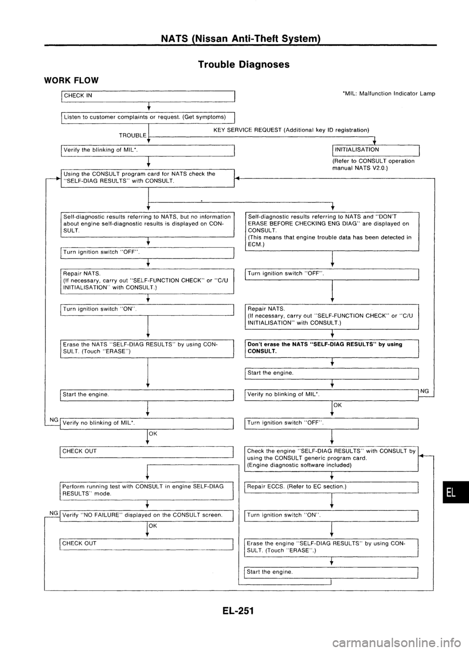
WORK FLOW
I
CHECK
IN
Listen tocustomer complaints orrequest. (Getsymptoms) 'MIL:
Malfunction IndicatorLamp
KEY SERVICE REQUEST (Additional keyIDregistration)
TROUBLE
I
Verify theblinking ofMIL'.
(RefertoCONSULT operation
manual NATSV2.0.)
Using theCONSULT programcardforNATS check the
"SELF-DiAG RESULTS"withCONSULT.
Self-diagnostic resultsreferring toNATS, butnoinformation
about engine self-diagnostic resultsisdisplayed onCON-
SULT.
I
Turn ignition switch"OFF".
t
Repair NATS.
(If necessary, carryout"SELF-FUNCTION CHECK"or
"C/U
INITIALISATION" withCONSULT.) Self-diagnostic
resultsreferring toNATS and"DON'T
ERASE BEFORE CHECKING ENGDIAG" aredisplayed on
CONSULT.
(This means thatengine trouble datahasbeen detected in
ECM.)
Turn ignition switch"OFF".
I
Turn ignition switch"ON".
I
Repair
NATS.
(If necessary, carryout"SELF-FUNCTION CHECK"or
"C/U
INITIALISATION" withCONSULT.)
Erase theNATS "SELF-DIAG RESULTS"byusing CON-
SUL T.(Touch "ERASE")
I
Start theengine.
NG Verify noblinking ofMIL'.
OK
I
CHECK OUT
-
Perform runningtestwith CONSULT inengine SELF-DiAG
RESULTS" mode.
NG Verify "NOFAILURE" displayedonthe CONSULT screen.
OK
I
CHECK OUT
Don't
erase theNATS "SELF.DlAG RESULTS"byusing
CONSULT.
I
Start theengine.
Verify noblinking ofMIL'.
OK
I
Turn ignition switch"OFF".
~
Check theengine "SELF-DiAG RESULTS"withCONSULT by
using theCONSULT genericprogram card.
(Engine diagnostic softwareincluded)
Repair ECCS.(RefertoEC section.)
I
Turn ignition switch"ON".
Erase theengine "SELF-DIAG RESULTS"byusing CON-
SUL T.(Touch "ERASE".)
I
Start theengine.
NG
•
EL-251