Page 82 of 1701
Lowerseparating
gasket REPAIR
FORCOMPONENT PARTS
Control ValveAssembly (Cont'd)
g. Install newlower separating gasket,newlower intersepa-
rating gasket andlower separating plateinorder shown in
illustration.
Lower separating
plate
SAT244E
Separating
plate &gaskets
Lowerbody
> (~)
Boit
SAT124DA
h.
Install support platefixing bolts
CID
from bottom oflower
body andinstall separating gasketsandseparating plateas
a set onlower bodyusing bolts
CID
asguides.
SAT125DA
i.
Temporarily installsupport platesonlower body.
Model 34X68 Lower
body
Inter and
upper bodies
SAT126D
Overdrive cancelsolenoid 7
.'
j.
Install lowerbodyoninter body using reamer bolts
(f)
as
guides andtighten reamer bolts
(f)
slightly.
2. Install a-rings toaD cancel solenoid, torqueconverter
clutch solenoid valveandharness connector.
• Apply ATF
toO-rings.
AT-82
Page 83 of 1701

REPAIRFORCOMPONENT PARTS
Control ValveAssembly (Cont'd)
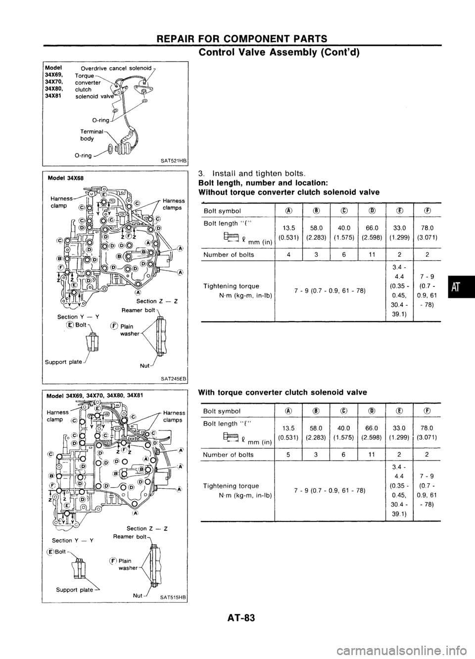
Model
34X69, 34X70,
34X80, 34X81 Overdrive
cancelsolenoid
Torque~ converter
clutch
'0
solenoid valv~
'"
o_rin~
Terminal
0
body
O-ring~
l\
SAT521HB
Section Z- Z
Reamer bolt
Model
34X68
•
Bolt
symbol
@
@
@
@
(!)
ffi
Bolt length "C"
13.558.0 40.0 66.0
33.078.0
~ Q
mm(in)
(0.531)
(2.283)(1.575) (2.598)(1.299)
(3.071)
Number ofbolts
4
3611
22
3.4 -
4.4 7-9
Tightening torque
7-9 (0.7 -0.9, 61-78) (0.35
-(0.7 -
N'm (kg-m, in-Ib)
0.45,
0.9,61
30.4 - -78)
39.1)
3.
Install andtighten bolts.
Bolt length, number andlocation:
Without torqueconverter clutchsolenoid valve
/
Nut
(:E)
Plain
washer
Section
y- y
@Bolt~
Support plate
r
SAT245EB
Section
y- y
Section
Z- Z
Reamer bolt With
torque converter clutchsolenoid valve
Bolt symbol
@
@
@
@
(!)
ffi
Bolt length "C"
13.558.0
40.0 66.033.0
78.0
~ Q
mm (in)
(0.531)
(2.283)
(1.575) (2.598)(1.299)
(3.071)
Number ofbolts
536
11 2
2
3.4 -
4.4 7-9
Tightening torque
7-9 (0.7 -0.9, 61-78) (0.35
-(0.7 -
N'm (kg-m, in-Ib)
0.45,
0.9,61
30.4 --
78)
39.1)
(ElBolt -
. S"PP~
en
Plain
washer
AT-83
Page 85 of 1701
Model34X69, 34X70, 34X80,34X81 REPAIR
FORCOMPONENT PARTS
Control ValveAssembly (Cant'd)
Model 34X68
Model
34X69,
34X70,
34X80,
34X81
Model
34X68
Model
34X69,
34X70,
34X80,
34X81
h,
Install support platesandtighten bolts
CID
tospecified
torque.
[j]:
3.4-4.4 N'm (0.35 -0.45 kg-m, 30.4-39.1 in-Ib)
SAT529HA
i.
Install tubeconnector andtubes tolower body,
• Install oilcircuit sideoftube connector faceup.
SAT603DB
SAT104DB
AT-8S
•
Page 126 of 1701
REPAIRFORCOMPONENT PARTS
Output Shaft,IdlerGear, Reduction PinionGear
and Bearing Retainer -Model 34X81(Cont'd)
• Roll paper around sealrings toprevent sealrings from
spreading.
B:
paper
Tape
0/ ~
,~
~ SAT661D
n :
Adjustment isrequired.
cED:
ApplyATF. Band
Servo Piston Assembly
Second servoreturn spring
SAT945HA
DISASSEMBL Y
1. Remove bandservo piston snapring.
2. Apply compressed airtooil hole intransmission caseto
remove 00servo piston retainer andband servo piston
assembly.
• Hold band servo piston assembly witharag.
AT-126
Page 145 of 1701
SAT341D
SAT438D
SAT439D
KV31101300 NAT064 ASSEMBLY
Adjustment 1(Cont'd)
OUTPUT SHAFTENDPLAY
- Model 34X81-
• Measure clearance betweensidecover andtheend ofthe
output shaftbearing.
• Select proper thickness ofadjusting shimsothat clearance
is within specifications.
1. Install bearing retainer foroutput shaft.
2. Install output shaftthrust needle bearing onbearing •
retainer.
3. Install output shaftontransmission case.
4. Measure dimensions"
£1"
and"
£2"
atside cover andthen
calculate dimension "A".
• Measure dimension
"f/'
and
"f
2"
inat least twoplaces.
"A":
Distance betweentransmission casefitting surface
and adjusting shimmating surface.
A
= f
1-£2 £2:
Height ofgauge
AT-145
Page 165 of 1701

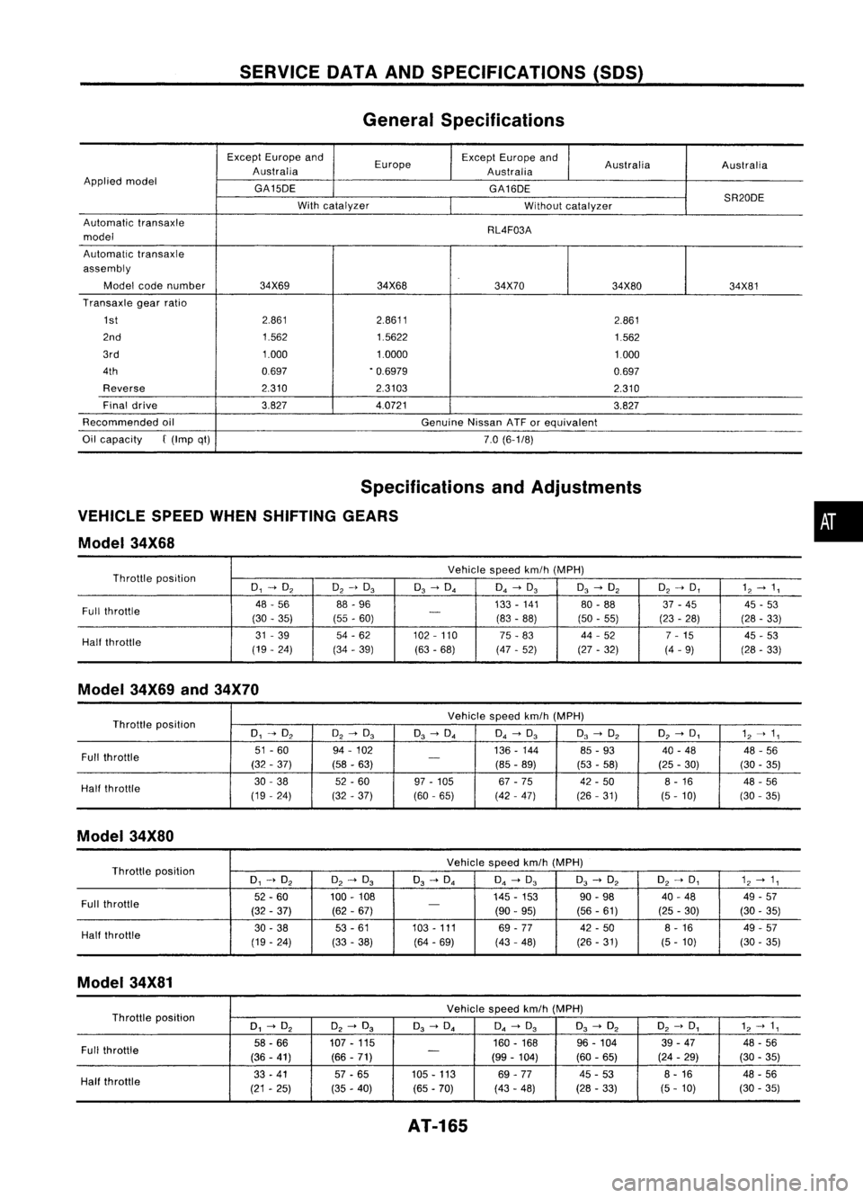
SERVICEOATAAND SPECIFICATIONS (SOS)
General Specifications
Except Europe and
Europe Except
Europe and
Australia Australia
Australia Australia
Applied model
GA150E GA160E
SR200E
With catalyzer
Withoutcatalyzer
Automatic transaxle
RL4F03A
model
Automatic transaxle
assembly
Model codenumber 34X69 34X68 34X70
34X8034X81
Transaxle gearratio
1st 2.861
2.8611
2.861
2nd 1.5621.5622
1.562
3rd 1.0001.0000
1.000
4th 0697.0.6979
0.697
Reverse 2.3102.3103
2.310
Final drive 3.8274.0721
3.827
Recommended oil
GenuineNissanATForequivalent
Oil capacity
f
(Imp qt)
7.0(6-1/8)
Specifications andAdjustments
VEHICLE SPEEDWHENSHIFTING GEARS
Model 34X68
Throttle position Vehicle
speedkm/h(MPH)
0, -->O
2
O
2
-->0
3
0
3
-->O. O.-->0
3
0
3
-->O
2
O2-->D, 12--> 1,
Full throttle 48
-56 88-96 133-141 80-88 37-45 45-53
(30 -35) (55-60)
-
(83-88) (50-55) (23-28)
(28-33)
Half throttle 31
-39 54-62 102-110
75-83 44
-52
7-15 45-53
(19 -24) (34-39) (63-68) (47-52) (27-32) (4-9)
(28-33)
Model 34X69and34X70
Throttle position Vehicle
speedkm/h(MPH)
0, -->O
2
O
2
-->0
3
0
3
-->O. O.-->0
3
0
3
-->O
2
O
2
-->0, 1
2
--> 1,
Full throttle 51
-60
94-102 136-144 85-93 40-48 48-56
(32 -37) (58-63)
-
(85-89) (53-58) (25-30)
(30-35)
Half throttle 30
-38 52-60 97-105 67-75 42-50 8-16 48-56
(19 -24)
(32-37) (60
-65) (42-47) (26-31)
(5-10) (30
-35)
Model 34X80
Throttle position Vehicle
speedkm/h(MPH)
0, -->O
2
O
2
-->0
3
0
3
-->O. O.-->0
3
0
3
-->O
2
O2-->0, 1
2
--> 1,
Full throttle 52.60
100-108 145-153 90.98
40-48 49-57
(32 -37) (62-67)
-
(90-95) (56
-61) (25-30) (30-35)
Half throttle 30
-38 53
-61 103-111
69-77 42
-50 8-16 49-57
(19 -24)
(33-38) (64-69) (43
-48) (26-31) (5-10) (30-35)
Model 34X81
Throttle position Vehicle
speedkm/h(MPH)
0, -->O
2
O
2
-->0
3
0
3
-->O.
O.
-->0
3
0
3
-->O
2
O
2
-->0, 1
2
--> 1,
Full throttle 58.66
107.115 160.168
96-104 39-47 48-56
(36 -41) (66-71)
-
(99-104) (60-65) (24-29) (30-35)
Half throttle 33
-41 57-65 105.113
69-77 45
-53 8.
16
48-56
(21 -25) (35-40) (65.70)
(43-48) (28
-33)
(5-10) (30
-35)
AT-165
•
Page 243 of 1701
INTERIORTRIM
Door Trim
(Coni' d)
REMOVAL -Door trim
4-door sedanand5-door hatchback
G)
Remove insidehandle escutcheon.
CID
Remove armrestfinisher frompower window switchassembly anddisconnect theconnector.
@
Remove screwsecuring pullhandle andremove pullhandle.
@
Remove windowregulator handle(Manual windowmodels).
@
Remove bolts,screws andclips ~securing doorfinisher.
@ Lift outdoor finisher.
SEC. 251-267-809-828
Hook
:
~ Manual window regulator handle
Removal
(j)
~? .P"h
~ Flat-bladed
{} screwdriver
@~l
Squeeze theregulator handleclipinplace witha
screwdriver andremove theregulator handlefrom
the regulator shaft.
Set theregulator handleclipasshown infigure
CD.
Installation
Push theregulator handletoinstall itonto theregulator
shaft.
Install theregulator handleinplace asshown inthe figure
with thewindow completely closed.
8T-23
88T055
•
Page 277 of 1701
BRAKEHYDRAULIC LINE
Without anti-lock brakesystem
(Models withdual proportioning valvebuiltintomaster cylinder)
(built-in type)
Proportioningvalve
(Do notdisassemble.)
With anti-lock brakesystem
ASS actuator
L
Master cylinder
=
.
Primary line
- .Secondary line
~ 0:Flare nut
15 -18 (1.5 -1.8, 11-13)
• :Connecting bolt
17 -20 (1.7 -2.0, 12-14)
~ :N.m (kg-m. ft-Ib)
SBR086D
•
BR-7