Page 279 of 1701

CONTROLVALVE
Proportioning Valve
INSPECTION
CAUTION:
• Carefully monitorbrakefluidlevel atmaster cylinder.
• Use new brake fluid"DOT 3"or"DOT 4".
• Donot mix different typesofbrake fluids(DOT3,DOT 4).
• Becareful nottosplash brakefluidonpainted areas;itmay
cause paintdamage. Ifbrake fluidissplashed onpaint
areas, washitaway withwater immediately.
• Depress pedalslowly whenraising frontbrake pressure.
• Check rearbrake pressure 2seconds afterfront brake pres-
sure reaches specified value.
• For models withABS disconnect harnessconnectors from
ABS actuator relaybefore checking.
1.
Connect Tooltoair bleeders offront andrear brakes on
either
LH
or
RH
side.
2. Bleed airfrom theTool.
3. Check rearbrake pressure bydepressing brakepedal
(increasing frontbrake pressure).
Unit:kPa(bar, kg/cm
2,
psi)
Without ABS
I
With
ABS
Applied models
GA14DE,GA16DE,CD20 GA16DE'
SR20DE
Applied pressure 7.3556.375
5,394
(Front brake) (73.6,
75,1,067) (63.7,65,924)
(53.9,55,782)
3,432 -3,825 2,452-2,844
Output pressure 5,100
-5,492 (34.3-38.2, (245-28.4,
(Rear brake) (51.0
-54.9, 52-56, 739 -796) 35-39, 25-29,
498 -555) 356-412)
*
Models forAustralia
If
output pressure isout ofspecifications, replacedualpro- •••
portioning valve(separated type)ormaster cylinder assem-
bly (built-in type).
4. Bleed airafter disconnecting theTool. Refer to"Bleeding
Procedure", BR-5.
BR-9
Page 282 of 1701

MASTERCYLINDER
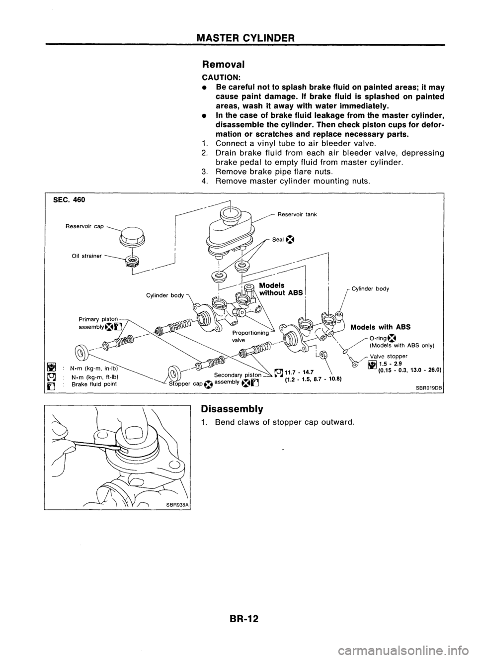
Removal
CAUTION:
• Becareful nottosplash brakefluidonpainted areas;itmay
cause paintdamage. Ifbrake fluidissplashed onpainted
areas, washitaway withwater immediately.
• Inthe case ofbrake fluidleakage fromthemaster cylinder,
disassemble thecylinder. Thencheck piston cupsfordefor-
mation orscratches andreplace necessary parts.
1. Connect avinyl tubetoair bleeder valve.
2. Drain brake fluidfrom each airbleeder valve,depressing
brake pedaltoempty fluidfrom master cylinder.
3. Remove brakepipeflare nuts.
4. Remove mastercylinder mounting nuts.
Models withASS
/O-ring~
'V
(ModelswithABS only)
'\~ /'Valve stopper
T@" ~
1.5.2.9
(0.15.0.3, 13.0•26.0)
o
l-~
~ 11.7 -14.7 \
(1.2 -1.5, 8.7-10.8)
SBR019DB
Seal~
___
Reservoir tank
jJ'JD~----
~ ..-:'J
C'9 ---
Secondarypiston
Stopper cap~assembly
~f]
Cylinder
body
N.m (kg-m, in-Ib)
N.m (kg-m. ft-Ib)
Brake fluidpoint
Reservoir
cap
----g
Oil strainer ----. ~
L------- -
SEC.
460
Disassembly
1. Bend claws ofstopper capoutward.
BR-12
Page 283 of 1701
SBR435B
SBR939A
Secondary piston
Primary piston
SBR012A
Models withABS
Secondary piston
Primary piston
_-rnIJ
SBR221BAMASTER
CYLINDER
Disassembly (Cont'd)
2. Remove valvestopper whilepiston ispushed intocylinder
(Models withASS only).
3. Remove pistonassemblies.
If itis difficult toremove secondary pistonassembly, gradually
apply compressed airthrough fluidoutlet.
4. Draw outreservoir tank.
Inspection
Check master cylinder innerwallforpin holes orscratches.
Replace ifdamaged.
Assembly
1. Insert secondary pistonassembly. Theninsert primary pis-
ton assembly.
• Pay attention todirection ofpiston cupsinfigure atleft.
Also, insert pistons squarely toavoid scratches oncylinder
bore.
• Pay attention toalignment ofsecondary pistonslitwith
valve stopper mounting holeofcylinder body(Formodels
with ABS only).
BR-13
•
Page 306 of 1701

PARKINGBRAKECONTROL
ItJ
3.'.'~ (0.33.0.... 28.6 •38.2)~
Rear RHcable "'"
SEC.
443
\;..,Reardrum model
,Lever assembly
~r.iil
~4.3-6.5
I
llrJ
3.2•4.3 "~(0.44 •0.66, 38.2•57.3)
~ ~15.7 -19.6 (0.33.0.44,28.6.38.2)
','(5' ..--,
jjf ..
(y -
2.0, 11.6 •14.5) ~1iI3.2 •4.3
"""'...~)\)')'))Jl--'
/, f
(0.33-0.44, 28.6-38.2)
m
" ,RearLHcab7e
Ad'
t t~
J,
e
r
<~
3.2•4.3 (0.33 -0.44, 28.6•38.2)
IUS
Ing nu~ ~'
I
Front \
~/ i
!cablem. ~\ I
Parking brake ,,~'::\'
I'
<> ~ ~
warning lampswitch
I
(~./?' ~
Boot /-
JJ~?
iii
3.2•4.3 ~3.2.4.3 (0.33 •0.44, 28.6-38.2)
~ M___
(0.33•0.44, 28.6-38.2)
iii
~ci~3; ~'~.44,
II]
3.2•4.3 (0.33 •0.44',28.6 -38.2)
Bracket
28.6_38.2)
Ill:
N.m(kg-m, In-Ib)
~: N.m(kg-m, ft-Ib) SBR028DA
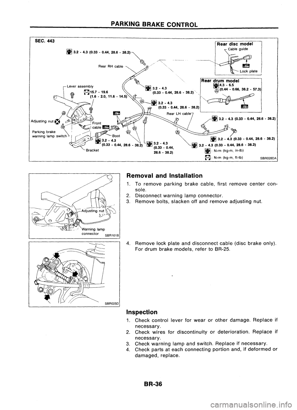
Removal andInstallation
1. To remove parkingbrakecable, firstremove centercon-
sole.
2. Disconnect warninglampconnector.
3. Remove bolts,slacken offand remove adjusting nut.
4. Remove lockplate anddisconnect cable(discbrake only).
For drum brake models, refertoBR-25.
Inspection
1. Check control leverforwear orother damage. Replaceif
necessary.
2. Check wiresfordiscontinuity ordeterioration. Replaceif
necessary.
3. Check warning lampandswitch. Replace ifnecessary.
4. Check partsateach connecting portionand,ifdeformed or
damaged, replace.
BR-36
Page 309 of 1701

ANTI-LOCKBRAKESYSTEM
System Components
Dual proportioning
valve
Rearwheel sensors
For LHD models, controlunit
is located onthe opposite side.
SBR048DB
Control unit
s::';o~'~W.
r
Magnetic flux~ _~-Coil
I .I
Tooth~ Sensorrotor
/ ~m~f onetooth
v:~-- System
Description
SENSOR
The sensor unitconsists ofagear-shaped sensorrotoranda
sensor element. Theelement contains abar magnet around
which acoil iswound. Thesensor isinstalled onthe back side
of the brake rotor.Sine-wave currentisgenerated bythe sen-
sor asthe wheel rotates. Thefrequency andvoltage increase(s) •
as the rotating speedincreases. :•
V: Induced electromotive force
SBR124B
SBR049DA CONTROL
UNIT
The control unitcomputes thewheel rotating speedbythe sig-
nal current sentfrom thesensor. Thenitsupplies aDC current
to the actuator solenoid valve.Italso controls ON-OFFopera-
tion ofthe valve relayandmotor relay.Ifany electrical malfunc-
tion should bedetected inthe system, thecontrol unitcauses
the warning lamptolight up.Inthis condition, theASS willbe
deactivated bythe control unit,andthevehicle's brakesystem
reverts tonormal operation.
BR-39
Page 324 of 1701
TROUBLEDIAGNOSES
Self-diagnosis (ForEurope) (ConI'd)
HOW TOREAD SELF-DIAGNOSTIC RESULTS(Malfunction codes)
• Determine thecode No.bycounting thenumber oftimes thewarning lampflashes onand off.
• The malfunction codechart isgiven onthe next page.
Example
Warning lampON
Warning lampOFF Malfunction
codeNo.12and 23
c
a
3seconds (Clearance betweencodeNo.)
b 0.6second (Tendigits)
c 0.3second (Onedigit)
SBR877CA
HOW TOERASE SELF-DIAGNOSTIC RESULTS(Malfunction codes)
• Disconnect ASScontrol unitconnectors orbattery negative terminalforatleast oneminute.
• When usingCONSULT, touch"ERASE" onthe CONSULT screenwithself-diagnostic resultsmode.
BR-54
Page 326 of 1701

TROUBLEDIAGNOSES
Self-diagnosis (ExceptEurope)
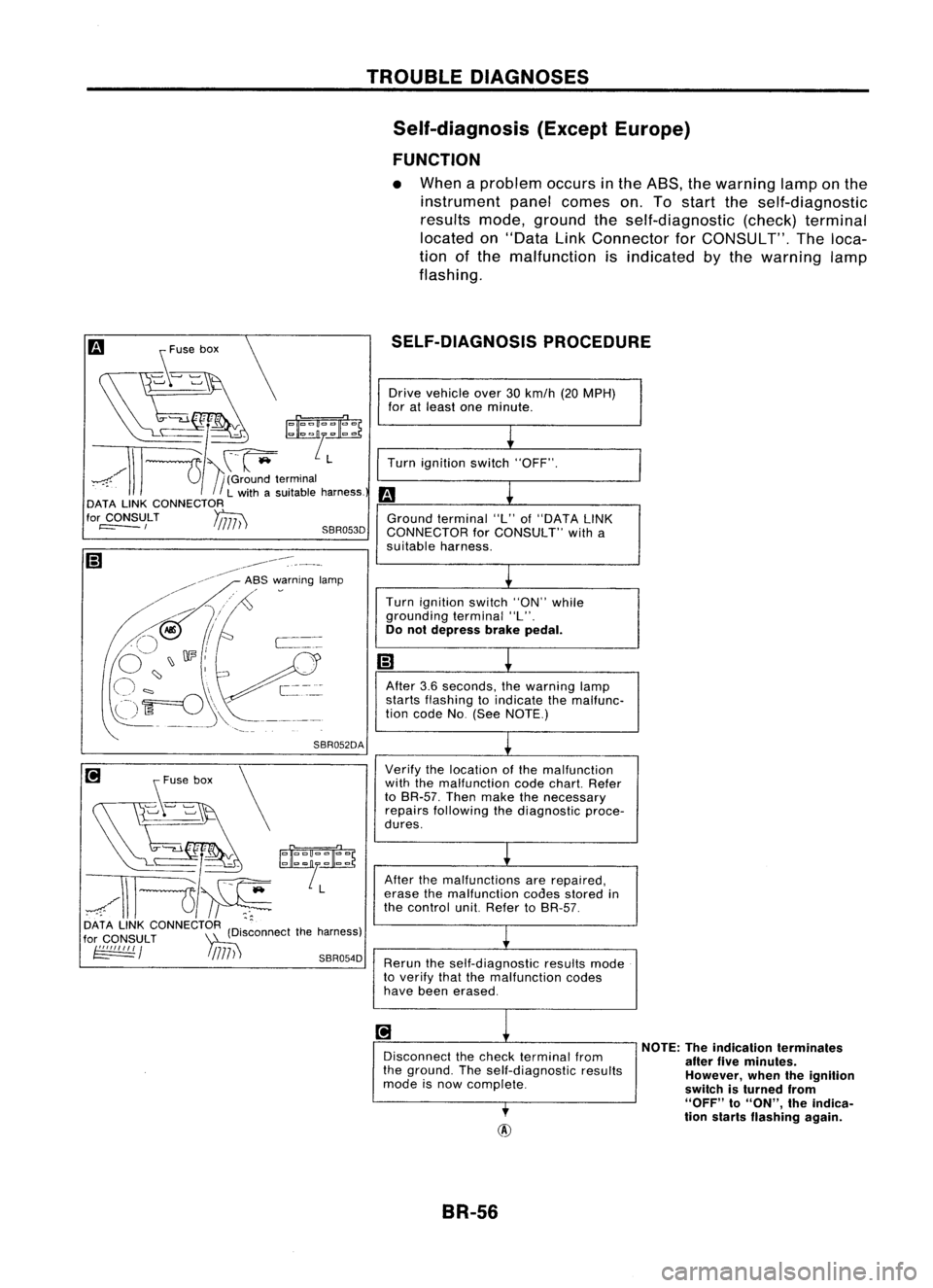
FUNCTION
• When aproblem occursinthe ASS, thewarning lamponthe
instrument panelcomes on.Tostart theself-diagnostic
results mode,ground theself-diagnostic (check)terminal
located on"Data LinkConnector forCONSULT". Theloca-
tion ofthe malfunction isindicated bythe warning lamp
flashing.
SELF-DIAGNOSIS PROCEDURE
[i
s~'~" \
~/''':~~
~/\\l---u~
DATA LINKCONNECTOR (D'.ctthe harness)
for
CONSULT
~Isconne
~ / !
/717) ')
SBR054D
Drive
vehicle over30km/h (20MPH)
for atleast oneminute.
~
Turn ignition switch"OFF".
m
L
Ground terminal "L"of"DATA LINK
CONNECTOR forCONSULT" witha
suitable harness.
L
Turn ignition switch"ON"while
grounding terminal"L".
Do not depress brakepedal.
m
~
After 3.6seconds, thewarning lamp
starts flashing toindicate themalfunc-
tion code No(See NOTE.)
~
Verify thelocation ofthe malfunction
with themalfunction codechart. Refer
to BR-57. Thenmake thenecessary
repairs following thediagnostic proce-
dures.
L
After themalfunctions arerepaired,
erase themalfunction codesstored in
the control unit.Refer toBR-57.
~
Rerun theself-diagnostic resultsmode
to verify thatthemalfunction codes
have been erased.
~
1
Disconnect thecheck terminal from
the ground. Theself-diagnostic results
mode isnow complete.
,
NOTE:
Theindication terminates
after fiveminutes.
However, whentheignition
switch isturned from
"OFF"
to
"ON",
theindica-
tion starts flashing again.
BR-56
Page 331 of 1701
1)Turn ignition switchOFF.
2) Connect CONSULT toData LinkConnector forCONSULT.
3) Turn ignition switchON.
1
m
1)Touch "START" onCONSULT screen.
Iil
2)Touch "A8S".
t!J
3)Touch "DATA MONITOR".
~
I!l
1)Touch "SETTING" on"SELECT MONITOR ITEM"screen.
(I
2)Touch "LONG TIME"on"SET RECORDING COND"screen.
I!l
3)Touch "START" on"SELECT MONITOR ITEM".
TROUBLE
DIAGNOSES
CONSULT Inspection Procedure (Cont'd)
DATA MONITOR PROCEDURE
Iil
~ SELECT
SYSTEM
01
ENGINE
AfT
AIRBAG ABS
IVMS
SBR104D
m
NISSAN
CONSULT EE940
+
I fDU
I
START
I
SUB
MODE
I
SEF253Q
t!J
I~
SELECT DIAGMODE
01
I
SELF-DIAG
RESULTS
I
I
DATA
MONITOR
I
I
ACTIVE
TEST
I
I
ECU
PART NUMBER
I
I
I
•
I
I
SST412B
I!l
I~SELECT
MONITOR ITEM
ALL SIGNALS
SELECTION FROMMENU
SETTING
II
START
SBR936C
AUTO TRIG
LONGTIME
SBR937C BR-61