Page 57 of 521
€3 Cooling System (AJ16)
4.1.2 COOLING SYSTEM CONFIGURATION
The configuration of the cooling system for normally aspirated and supercharged engines is shown in Fig. 1 and Fig. 2. The main coolant flows, with the system at normal operating temperature (i.e. with the engine thermostat open),
are indicated by arrows.
1
2 7
J26-265
1. Header Tank 4. Thermostat 7. Heater
2. Radiator 5. Throttle Body 8. Heater Pump
3. Water Pump 6. Engine 9. Heater Valve
Fig. 1 Cooling System, Normally Aspirated Engine
1
i-266
1. Header Tank 5. Water Pump 9. Engine
2. Supercharger Pump 6. Thermostat IO. Heater
3. Supercharger Radiator 7. Throttle Body 11. Heater Pump
4. Main Radiator 8. Intercooler 12. Heater Valve
Fig.
2 Cooling System, Supercharged Engine
Issue 1 August 1994 X300 VSM 2
Page 58 of 521

area washed to remove all traces of coolant.
CAUTION: To prevent the possibility of damage to the heater circuit pump and supercharger pump (where fitted),
the pumps should be electrically isolated if the ignition has to be turned ON while the cooling system is
drained.
WARNING: DO NOT REMOVE THE HEADER TANK PRESSURE CAP WHILE THE ENGINE IS HOT. IF THE CAP MUST
BE REMOVED, PROTECT THE HANDS AGAINST ESCAPING STEAM AND SLOWLY TURN THE CAP ANTI
- CLOCKWISE UNTIL THE EXCESS PRESSURE CAN ESCAPE. LEAVE THE CAP IN THIS POSITION UNTIL
ALL THE STEAM AND PRESSURE HAS ESCAPED AND THEN REMOVE THE CAP COMPLETELY.
WARNING: WHEN DRAINING THE COOLANT WITH THE ENGINE HOT, PROTECT THE HANDS AGAINST CONTACT
WITH HOT COOLANT.
WARNING: WHEN WORKING WITHIN THE ENGINE COMPARTMENT, KEEP CLEAR OF THE RADIATOR COOLING
FANS. THE FANS COULD START WITHOUT WARNING EVEN IF THE ENGINE IS NOT RUNNING.
4.1.3.2 Working Practices
Whenfilling thesystem with coolant,ensurethatthevehicle isstanding on a level surfaceandthatthecoolant is poured
in slowly so that airlocks are not introduced into the system. Airlocks can seriously affect the operation of the climate
control system and can cause damage to the heater circuit pump (and supercharger circuit pump if fitted).
Cooling System (AJ16)
4.1.3 SERVICE PROCEDURES
4.1.3.1 Safety Precautions
The anti-freeze specified in Appendix AI must be used wherever possible. It is designed to afford the maximum cor- rosion protection to all metals found in the engine cooling system, as well as having the frost protection properties
necessary during the winter months.
Should
it not be available, then anti-freeze conforming to Ford Motor Company specification ESLbM97B49-A may be
used. To provide optimum temperature and corrosion protection, the specified anti-freeze concentration must always
be used.
Once coolant has been drained from the system,
it must be discarded and not reused. Anti-freeze is harmful to the
environment. Used coolant must be disposed of safely and never poured down a drain connected to the public sewer.
CAUTION: Never fill or topup the system with water only.
CAUTION : Anti-freeze is harmful to paintwork. Coolant spillages must be wiped up immediately and the affected
Hose clips should always be positioned so that there is proper access for tightening and that the clip does not foul or
interfere with the operation of any components.
Drive belts must always be tensioned to the specified value and the tension checked
at the correct point on the belt.
This information is given in Subsection IV in the preliminary pages.
0
When tightening components, the torque figures given in Sukection II in the preliminary pages should always be
used for the fastenings listed.
4.1.3.3 Coolant Change
The coolant must be changed at intervals of four years. The system should be drained from the radiator drain plug,
flushed and filled with fresh coolant. Flushing should be carried out thoroughly to remove all the old coolant from the
engineand heater matrix. (The heatervalve isopen withthe ignition OFF). AfterfiIling,checkthecoolant concentration
with a hydrometer. For the specified anti-freeze and coolant concentration, see Appendix AI.
X300 VSM 3 Issue 1 August 1994
Page 59 of 521

€3 Cooling System (AJ16)
4.1.4 DRAIN AND FILL PROCEDURES
4.1.4.1 Radiator, Drain
. Place a drain tray in position underthe radiator drain plug
. Remove the header tank pressure cap. Release the captive
Tighten the radiator drain plug.
CAUTION: This procedure does not drain the heater circuit.
(Fig. 1).
radiator drain plug and drain the coolant.
4.1.4.2 Engh-, Drain
m:
. Drain the radiator. (See the procedure above).
. Place a drain tray under the cylinder block drain plug (Fig.
Remove the block drain plug and drain the coolant.
. Fit the block drain plug.
This procedure
should only be necessary when the
engine is being dismantled.
2).
Fig. 1
Fia. 2
WAm. DO NOT REMOVE THE HEADER TANK PRESSURE CAP WHILE THE ENGINE IS HOT. IF THE CAP MUST
BE REMOVED, PROTECT THE HANDS AGAINST ESCAPING STEAM AND SLOWLY TURN THE CAP ANTI- CLOCKWISE UNTIL THE EXCESS PRESSURE CAN ESCAPE. LEAVE THE CAP IN THIS POSITION UNTIL ALL THE STEAM AND PRESSURE HAS ESCAPED AND THEN REMOVE THE CAP COMPLETELY.
WARNING: WHEN DRAINING THE COOLANT WITH THE ENGINE HOT, PROTECT THE HANDS AGAINST CONTACT
WITH HOT COOLANT.
4.1.4.3 Radiator, Fill
. Add coolant until the level in the header tank is steady at MAX. (Do not fit the header tank cap).
. Switch on the ignition. (The climate control system must be OFF).
Start the engine and wait until the cooling fans operate for the second time. (The engine speed may be raised to
While the cooling fans are operating, raise the engine speed to 1500 RPM for one minute. Return to idle speed.
. Switch off the ignition and wait for one minute.
Check that the coolant level in the header tank is between MAX and 10 mm above MAX. Add coolant as necessary.
Fit the header tank cap.
reduce
the warm up time).
Issue 1 August 1994 4 X300 VSM
Page 60 of 521

.
0
0
Cooling System (AJ1
4.1.4.4 Complete System, Fill
. Add coolant until the level in the header tank is steady at MAX. (Do not fit the header tank cap).
m Switch on the ignition. (The climate control system must be OFF).
Start the engine and wait until the cooling fans operate for the second time. (The engine speed may be raised to
. While the cooling fans are operating, raise the engine speed to 1500 RPM for one minute. Return to idle speed.
. Turn the climate control system ON. Set the temperature to HI. Manually select a fan speed of approximately 50%.
. Run the engine for four minutes. Ensure that the climate control system outlet airtemperature is hot to very hot and
that there is no noise from the heater coolant circulating pump. (The engine speed may be raised to assist with heat- ing).
reduce the warm up time).
. Switch off the ignition and wait for one minute.
. Check that the coolant level in the header tank is between MAX and 10 mm above MAX. Add coolant as necessary.
Fit the header tank cap.
X300 VSM 5 Issue 1 August 1994
Page 61 of 521

4.1.5 FAULT DIAGNOSIS
4.1.5.1 Introduction
The following diagnostic procedures are provided to assist properly qualified persons to identify and rectify the faults
in the system which are most likely to be encountered. Reference is made to the Electrical Diagnostic Manual (EDM),
which should be consulted for all electrical faults. When investigating faults relating to temperature, the prevailing
ambient temperature conditions should be taken into account. The climate control system is dealt with in Section 14.
Possible Cause
Thermostat stuck closed
Incorrect thermostat rating
Faulty temperature gauge
Faulty temperature transmitter
4.1.5.2 Diagnostic Procedures
Check
Test thermostat
Check thermostat operating
temperature
Refer to EDM
Refer to EDM
Symptom
herheating
Cooling fan(s) not operating 3verheating at
dle
roo cold
Refer to EDM
Incorrect thermostat rating
Thermostat not fitted
Cooling
fan(s) operating con-
tinuously Faulty temperature gauge
Faulty temperature transmitter
Radiator
core blocked
Radiator grille obstructed
Check thermostat operating
temperature
Remove thermostat housing
and inspect
Refer to EDM
Refer to EDM
Refer to EDM
Concentration of
anti
-freeze too high
Drive belt slack
Drive belt broken
Water pump seized
Insufficient coolant
Internally collapsed hoses
Incorrect ignition timing
Fuel
/ air mixture too weak
Incorrect valve
timing
Cylinder head gasket leaking
Brakes binding Check
for
hotspots in radiator
Check grille for obstruction
Check strength of coolant
Check belt tension
Visual check
Slacken drive belt and turn
water
pump pulley by hand.
Check belt for damage
Check coolant level
Pressure test system and
check for deformation of hoses
Refer to EDM
Refer to EDM
Check valve
timing
Pressure-test system. (Check
for contamination of coolant
in header tank)
Check brake calipers for stick
-
ing pistons and seized brake
pad pins
Thermostat stuck open
I Test thermostat
Remedy
Renew thermostat
Renew thermostat
Renew gauge
Renew transmitter
Flush
or renew radiator
Remove obstruction from
grille
Drain and fill
with coolant of
correct concentration
Adjust belt to correct tension
or renew belt
if worn
Renew belt
Renew water pump. Renew
drive belt
if required
Top-up coolant
Renew hoses as required
Rectify
as required
Rectify
as required
Correct valve
timing
Renew head gasket
Rectify
as required
Rectify
as required
Renew thermostat
Renew thermostat
Fit thermostat
Rectify
as required
Renew gauge
Renew transmitter
0
e
0
0
Issue 1 August 1994 X300 VSM
Page 62 of 521

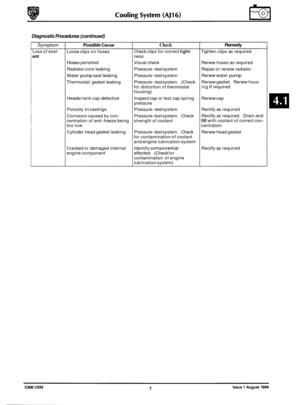
Diagnostic Procedures (continued)
Symptom
Loss of cool-
Possible Cause Check
Loose clips on hoses
Hoses perished Visual check
Radiator core leaking Pressure
-test system
Water
pump seal leaking Pressure-test system
Thermostat gasket leaking Pressure
-test system. (Check
for distortion of thermostat
housing)
Inspect cap or test cap spring
pressure
Pressure
-test system. Check
strength of coolant
Pressure
-test system. Check
for contamination of coolant
and engine lubrication system
Identify
component(s)
contamination of engine
lubrication system)
Check
clips for correct
tight-
ness
Header tank cap defective
Porosity
in castings Pressure-test system
Corrosion caused by con
-
centration of anti-freeze being
too low
Cylinder head gasket leaking
Cracked or damaged internal
engine component affected. (Check for
Remedy
Tighten clips as required
Renew hoses as required
Repair or renew radiator
Renew water
pump
Renew gasket. Renew hous-
ing if required
Renew cap
Rectify as required
Rectify as required. Drain and
fill with coolant of correct con-
centration
Renew head gasket
Rectify as required
Page 63 of 521
Page 64 of 521

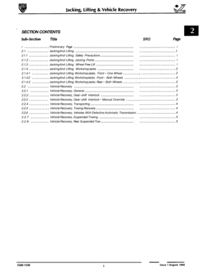
SECTION CON TENTS
Subsection Titie SRO Page
it0 IV ............ Preliminarypages .................................................................... i
4.2.1 ............. Cooling System Description ........................................................... 1
4.2.1.1 ........... Cooling System Description. Major Components .......................................... 1
4.2.1.2 ........... Cooling System Description. Components for Climate Control System ........................ 1
4.2.1.3 ........... Cooling System Description. Operation .................................................. 1
4.2.2 ............. Cooling System Configuration .......................................................... 2
4.2.3
............. Service Procedures ................................................................... 3
4.2.3.1
........... Service Procedures. Safety Precautions .................................................. 3
4.2.3.2
........... Service Procedures. Working Practices .................................................. 3
4.2.3.3
........... Service Procedures. Coolant Change .................................................... 3
4.2.4
............. Drain and Fill Procedures ............................................................. 4
4.2.4.1
........... Drain and Fill Procedures. Radiator, Drain ............................................... 4
4.2.4.2
........... Drain and Fill Procedures. Radiator, Fill ................................................. 4
* 4.2.4.3 ........... Drain and Fill Procedures. Complete System. Fill .......................................... 4
4.2.4.4
........... Drain and Fill Procedures. System. Air Bleeding ........................................... 4
4.2.5
............. Fault Diagnosis ...................................................................... 5
4.2.5.1
........... Fault Diagnosis. introduction ........................................................... 5
4.2.5.2
........... Fault Diagnosis. Diagnostic Procedures .................................................. 5
X300 VSM i Issue 1 August 1994