Page 417 of 521

General Fitting Instructions
In Fig. 1 and Fig. 2, this page,’K indicates the metric
type and ’B’ the UNF type.
Hose ends differ slightly between metric and UNF (Fig.
1). Gaskets are not used with metric hoses; the metric hose fit- ting seals against the bottom of the port and consequently
there is a gap between the hexagonal face of the hose fitting
and the cylinder (Fig.
2A). The UNF hose fitting is sealed on
the brakecylinder or caliperface by a copper gasket (Fig.
2B).
Pipe sizes (outside diameter) for UNF are 3/16 in., 1/4 in. and
5/16 in. Metric pipe sizes are 4,75 mm, 6 mm and 8 mm. The 4,75 mm pipe is exactly the same diameter as 3/16 in. pipe.
The 6 mm pipe is 0.014 in. smaller than 1/4 in. pipe. The 8
mm pipe is 0.002 in. larger than 5/16 in. pipe.
Convex flares for metric brake pipes have a different form
thanthoseon UNF brake pipes. When making pipesfor met
- ric equipment, metric pipe flaring tools must be used.
The greatest danger lies with the confusion of
10 mm and 3/8 in. UNF pipe nuts used for 3/16 in. (or 4,75 mm) pipe. The 318 in. UNF pipe nut or hose can be screwed into a 10 mm port, but is very slack and easily stripped. The thread en- gagement is very weak and cannot provide an adequate
seal. The opposite condition, a 10 mm nut in a 318 in. port,
will cause difficulty during fitting. The
10 mm nut will screw
in for one or two turns and then seize. It has a crossed thread
‘feel’ and
it is impossible to force the nut far enough to seal
the pipe. With female pipe nutsthe position is reversed. The
other combinations are so different that there is no danger
of confusion.
A3.2.12 Keys And Keyways
Remove burrs from the edges of keyways with a fine file and
clean thoroughly before attempting to refit the key. Clean
and inspect the key closely. Keys are suitable for refitting
only
if no indentations exist (which would indicate the onset
of wear).
A3.2.13 Split Pins
Fit new split pins throughout when replacing any unit. Al- ways fit split pins where split pins were originally used. Do not substitute spring washers for split pins. All split pins
should be fitted as shown (Fig. 3) unless otherwise stated.
A3.2.14 Tab Washers
Fit new tab washers in all places where they where used
originally. Never refit a used tab washer. Ensure that the
new tab washer is of the same design as that which was re
- moved.
A3.2.15 Special Fixing
Bolts with a blue coating applied to the thread are used in various areas ofthevehicle. Should any of these bolts be re- moved, they MUST be replaced with NEW bolts of the same
type. Nyloc nuts are used in various areas of the vehicle. If removed these MUST be replaced with NEW nuts of the
same type.
-A
507 008
Fia. 1
Fia. 2
Fig. 3 I
X300 VSM Issue 1 August 1994 6
Page 418 of 521

- A3.2.19 Unified Thread Identification - Bolts
A circular recess is stamped in the upper surface of the bolt
head (1 Fig. 1).
A3.2.20 Unified Thread Identification - Nuts
A continuous line of circles is stamped on one of the flats of
the hexagon, parallel to the axis of the nut (2 Fig. 1).
A3.2.2 1 Unified Thread Identification - Studs, Brake
Rods, etc.
The component is reduced to the core diameter for a short
length at its extremity (3 Fig. 1).
A3.2.16 Nuts
When tightening a slotted or castellated nut, never slacken it in order to insert the split pin or locking wire, but tighten
it to align the next slot. The exception is in those recommended cases where slackening the nut forms part of an adjust- ment e.g. bearing endfloat or preload adjustment. If difficulty is experienced, alternative washers or nuts should be
selected, or a washer of a different thickness used. Where self-locking nuts have been removed, replace them with
new ones.
A3.2.17 Locking Wire
Fit new locking wire of the correct type to the assemblies incorporating it. Arrange the wire so that its tension tends
to tighten the bolt heads, or nuts, to which it is fitted.
A3.2.18 Screw Threads
Metricthreads to IS0 standards and UNF threads are used. See below forthread identification. Fixings with damaged
threads must always be discarded. Cleaning the threads with a die or tap impairs the strength and closeness of fit and
is not recommended. Always ensure that replacement bolts are of equal strength to those removed. Do not allow oil,
grease or jointing compound to enter blind threaded holes because the hydraulic action which would be generated
when screwing in the bolt or stud could split the housing. Oil the thread lightly before tightening to ensure
a free run- ning thread, except in the case of self locking nuts. Always tighten a nut or bolt to the recommended torque figure.
Damaged or corroded threads will affect the torque reading. To check or retighten a bolt or screw to a specified torque
figure, first slacken by a quarter of a turn, then retighten to the correct figure.
I
7
-3
‘2 507 011
Fig. 1
X300 VSM 7 Issue 1 August 1994
Page 419 of 521
General Fitting Instructions
J51 051
A3.3 TAPER ROLLER BEARINGS,
FAULT DIAGNOSIS
I
Fault
Bent cage.
Cause
Improper handling or use of tool.
Remedy
Renew the bearing.
Fault
Bent cage.
Cause
Improper handling or use of tool.
Remedy
Renew the bearing.
Fault
Galling.
Cause
Marks on roller ends due to overheating, lubricant failure or
overloading.
Remedy
Renew the bearing. Check the seals and ensure that the
bearing is properly lubricated.
Fault
Step wear.
Cause
Wear on the roller ends caused by fine abrasives.
Remedy
Clean all components and housings. Check the seals and
bearings, and renew if leaking, rough or noisy.
Fault
Fretting.
Cause
Corrosion caused by small movement of components with
no lubrication.
Remedy
Renew the bearing. Check the seals for leakage and ensure
that there is adequate lubrication.
J51 050
J51 052
X300 VSM Issue 1 August 1994 8
Page 420 of 521

6 Fault
Misalignment.
Cause
Outer track misalignment usually due to a foreign body under the track.
Remedy
Clean all components and replace or renew the bearing and
ensure that the new track is correctly seated.
Fault
Indentations.
Cause
Surfaces are depressed on the race and the trackcaused by
hard particles of foreign material.
Remedy
Clean all components and housings. Check the seals and 0 bearings, and renew if leaking, rough or noisy.
r-7 .. ..... .,;, :.'. ,.: __.. ........ .... ..T;....'...':... ...... ........... ,i ........ :;: .. .-.. .... : ........ - ..
1 056
Fault
Flaking.
Cause
Flaking of the surface material due to fatigue.
Remedy
Renew the bearing and clean all related components.
Fault
Indentations.
Cause
Surface indentations in the track caused by rollers either
vibrating or impact loading while the bearing is not rotating.
Remedy
Renew the bearing if rough or noisy.
Fault
Cage wear.
Cause
Wear around the outside diameter of the cage and roller
pockets caused by poor lubrication and abrasive material.
Remedy
Renew the bearings and check the condition of the seals.
J51058
Issue 1 August 1994 9 X300 VSM
Page 421 of 521

General Fitting Instructions
I
Fault
Roller wear.
Cause
Marks on track and rollers caused by fine abrasives.
Remedy
Clean all components and housings. Check the seals and
bearings, and renew if leaking, rough or noisy.
Fault
Cracked race.
Cause
Race cracked due to incorrect fitting to shaft, tipping or poor
seating.
Remedy
Renew the bearing and check the condition of the seals.
Fault
Discolouration.
Cause
Discolouration ranging from black to light brown caused by
moisture or incorrect use of lubricants.
Remedy
Reuse bearings if stains can be removed by light polishing
or if no evidence of overheating is apparent. Checkthe seals
and other component part condition. Renew as necessary.
51 060
[pzq-j - ..., .... *au
....... ........ e L. U
1
Fault
Discolouration.
Cause
Heat discolouration ranging from blue to faint yellow,
resulting from overload or incorrect lubricant. As excessive
heat can cause softening of tracks and rollers, check by
drawing a fine
file over a softened area. If faulty, the file will
grab and cut metal. If still hard, the file will skid over the
surface without removing any material.
Remedy
Renewthe bearings and seals if any heat damage is evident.
51 062
Issue 1 August 1994 X300 VSM 10
Page 422 of 521
6 Fault
Seizure.
Cause
Seizure caused by lack of lubrication, excessive loads or the
ingress of foreign matter.
Remedy
Renew the bearings. Check the seals for wear and ensure
that there is adequate lubrication.
Fault
Etching.
Cause
The bearing surfaces are grey or greyish black, with the
rollers and track material being etched away. This is usually
related to uneven spacing of the rollers.
Remedy - Renew the bearings. Check the seals for wear and ensure
that there is adequate lubrication.
Fault
Rotating track and inner race material removal.
Cause
Removal of material due to slippage. This can be caused by
poor fit, incorrect lubrication, overheating, overloading and
poor assembly.
Remedy
Renew the bearings and clean all related parts. Check the fit
and ensure the replacement bearings are the correct type.
Renew the shaft or housing if damaged.
J51 OS6
Issue 1 August 1994 11 X300 VSM
Page 423 of 521
Page 424 of 521

SECTION CON TENTS
Suh-Section Title SRO Page
i Toiii ............ PreliminaryPages ................................................................ i Toiii
A4.1
............. Body Repair, Introduction ............................................................. 1
A4.1.1 ........... Health And Safety .................................................................... 1
A4.1.2 ........... Notification Of Hazards ............................................................... 2
A4.1.3 ........... Potential Risks ....................................................................... \
3
A4.1.3.1
.......... Potential Risks. Paint ................................................................. 3
A4.1.3.2
.......... Potential Risks. Applied Heat (Welding) .................................................. 3
A4.1.3.3 .......... Potential Risks. Metal Repair ........................................................... 3
A4.1.4 ........... Precautions ........................................................................\
. 3
A4.1.4.1 ..........
A4.1.4.2 ..........
A4.1.4.3 ..........
A4.1.5 ...........
A4.1.5.1 ..........
A4.1.6 ...........
A4.1.6.1 ..........
A4.1.6.2 ..........
A4.1.6.3 ..........
A4.1.6.4 ..........
A4.1.6.5 ..........
A4.1.6.6. .........
Precautions. Paint .................................................................... 3
Precautions. Applied Heat
............................................................. 3
Precautions. Metal Repair ............................................................. 3
General Repair Notes ................................................................. 4
Welding & Gas Processes. Special Notes ................................................. 4
Plastic Component & Trim Materials. - Table ............................................. 5
Plastics. Explanatory Notes ............................................................ 5
Plastics. Handling Notes .............................................................. 5
Recycled Materials
................................................................... 5
Plastics. Component Location & Type - External. Illustration ................................. 6
Plastics. Component Location
& Type - Internal. Illustration ................................. 7
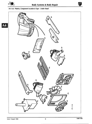
Plastics. Component Location & Type - Underhood. Illustration .............................. 8
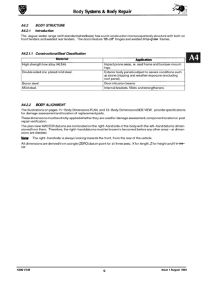
A4.2 ............. Body Structure. ...................................................................... 9
A4.2.1 ........... Body Structure. Introduction ........................................................... 9
A4.2.2.1 .......... Body Alignment. Datum Location ...................................................... 10
A4.2.2.2 .......... Body Alignment. Plan View - Key to Illustration .......................................... 10
A4.2.2.3 .......... Body Alignment. Side View - Key to Illustration .......................................... 12
A4.2.3 ........... Zinc Coated Panels .................................................................. 14
A4.2.3.1 .......... Zinc Coated Panels. Description ....................................................... 14
A4.2.3.2
.......... Zinc Coated Panels. Welding Preparation ............................................... 14
A4.2.3.3
.......... Zinc Coated Panels. Body Fillers ....................................................... 14
A4.2.3.4
.......... Zinc Coated Panels. Refinishing ....................................................... 14
A4.2.4
........... Panels -Associated. Renew ..................................... 77.10.02 ............ 15
A4.2.5
........... Surfaces (Old). Prepare .......................................... 77.10.03 ............ 16
A4.2.5.1 .......... Surfaces (New). Prepare ......................................... 77.10.04 ............ 16
A4.2.5.2 .......... Panels -Align And Weld ........................................ 77.10.05 & 06 ....... 17
A4.2.6 ........... Cutting And Welding Symbols ......................................................... 18
A4.3.1 ........... Adhesive. Sealers and Body Protection - Approved Systems ................................ 19
A4.3.
1 . 1 .......... Body Sealing & Preservation Manual - Section Relevance ................................. 19 A4.3.2 ........... Cavity Wax Injection ................................................................ 19
A4.3.2.1
.......... Cavity Wax Injection Points - Front. Illustration .......................................... 20
A4.3.2.2. ......... Cavity Wax Injection Points - Rear, Illustration ........................................... 21
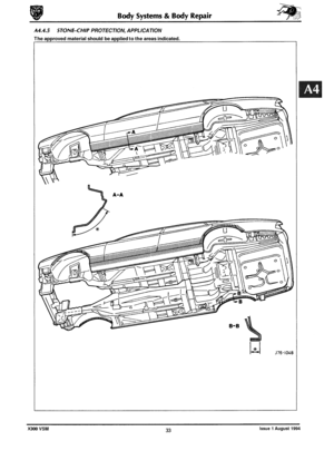
A4.3.3 ........... Underseal. Application Area .......................................................... 22
A4.3.4
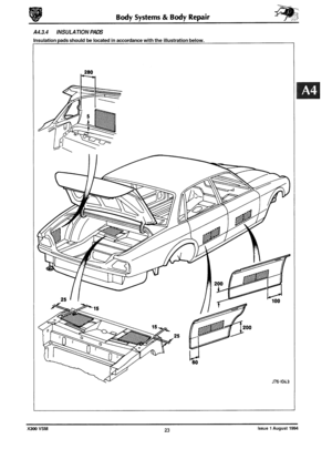
........... Insulation Pads. Location ............................................................. 23
A4.3.5
........... Foamlnjection ..................................................................... 24
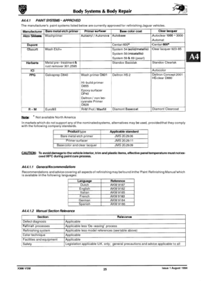
A4.4.1 ........... Paint Systems - Approved. Table ...................................................... 25
A4.4.1.1
.......... General Recommendations (Paint Refinishing Manual) .................................... 25
A4.4.1.2
.......... Paint Refinishing Manual. Section Relevance ............................................ 25
A4.4.2
........... ‘Black-Out’ Areas. Illustration ......................................................... 26
A4.4.3 ........... Anti-theft labels .................................................................... 27
A4.4.3.1
.......... Anti-theft labels. Original Components ................................................ 27
A4.4.3.2
.......... Anti-theft Labels. Replacement Components ............................................ 27
A4.4.3.3 .......... Anti-theft Labels. Procurement ........................................................ 27
A4.4.3.4
.......... Anti-theft Labels. Location -Front ..................................................... 28
A4.4.3.5
.......... Anti-theft Labels. Location - Rear ...................................................... 29
A4.4.3.7.
......... Anti-theft Labels. Fitting Process ....................................................... 31
A4.2.1.1
.......... Body Structure.
Constructional Steel Classification - Table .................................. 9
A4.2.2 ........... BodyAlignment ..................................................................... 9
A4.4.3.6 .......... Anti-theft Labels. Location -Power unit & Transmission ................................... 30