Page 129 of 521

Manual Transmission & Clutch (AJ16)
'ossible Cause
:Iutch Fault
'rimary pinion bear-
ng
ncorrect fitting nethod
Clutch Fault Diagnosis
Check
Check for worn clutch driven plate
hub splines
Check for wear in bearing
Damage may be caused by
acci- dental loading during fitting
Symptom
:I utch knocks
herloading vehicle
hiving with
left foot
,esting on clutch )edal
:ractured clutch )late
Check mating components for
damage
Refer to owners handbook for per
-
missible load details
Check as described under 'slipping
clutch'
Excessive
lining wear
lperating mechan-
sm faulty
:Iutch unit faults
3rabbing clutch
harsh engagement
'rom standing start,
Iften followed by clutch
udder) Check
operating mechanism for
wear and binding which usually
indicates
a binding withdrawal
race thrust bearing
Check pedal for sticking parts in
-
cluding return spring
Check for oil on friction driven
plate
Checkclutch plate and flywheel for
wear. Check flywheel
runout. Check also for glazing on driven
plate linings
Check for driven plate hub splines
sticking on pinion shaft.
Check pinion shaft for wear.
Check for broken or weak pressure
springs.
Check torque damper springs in
clutch driven
plate
hgine mounting Check
for damaged or deteriorated
engine mountings.
Check fixings for tightness
Remedy
Renew driven plate
Renew as necessary
Always support trans
- mission weight during fitting
Renew driven plate
Fit replacement clutch as-
sembly
Fit replacement clutch as- sembly
Free
off bearing. Renew as
necessary
Free
off pedal and check for
damaged and distorted
parts.
Renew
if necessary
Clean
off cover.
Renew faces.
Rectify oil
leak
Reclaim or renew as appli-
cable
Free driven plate, and check
for wear and distortion
Renew
if necessary
Renew
if necessary
Issue 1 August 1994 12 X300 VSM
Page 130 of 521
![JAGUAR XJ6 1994 2.G Workshop Manual Clutch Fault Diagnosis
Symptom
Slipping clutch
[indicated by vehicle
speed not responding to
engine speed increase)
]ragging or spinning :lutch
Manual Transmission & Clutch (AJ16)
Poss JAGUAR XJ6 1994 2.G Workshop Manual Clutch Fault Diagnosis
Symptom
Slipping clutch
[indicated by vehicle
speed not responding to
engine speed increase)
]ragging or spinning :lutch
Manual Transmission & Clutch (AJ16)
Poss](/manual-img/21/7690/w960_7690-129.png)
Clutch Fault Diagnosis
Symptom
Slipping clutch
[indicated by vehicle
speed not responding to
engine speed increase)
]ragging or spinning :lutch
Manual Transmission & Clutch (AJ16)
Possible Cause
Poor driving tech- nique
Operating mechan
-
ism faulty
Clutch unit faults
Operating mechan
-
ism faulty
Zlutch unit faults
2lutch unit faults
Check
Ensure that none of the remedy
conditions prevail
Checkfor binding withdrawal lever
Check for binding of clutch pedal
movement components
Check for oil on friction faces
Check for binding withdrawal lever
Check for binding of clutch pedal
movement components
Check for oil on friction faces
Check for broken or weak pressure
springs
.-
Check clutch plates and flywheel
for wear and distortion
Check clutch driven plate for frac
- tures and distortion.
Damage may be caused by acci
-
dental loading during assembly of
transmission to engine.
Always support transmission
weight during refitting
Check for primary pinion bearing
seized
Check clutch driven hub for bind
- ing on primary pinion splines.
Check for too thick friction linings.
Ensure linings
are good
Check for foreign matter in clutch
unit
Remedv
Do not increase engine speed
with clutch paGially' en-
gaged. Do not drive with left foot
resting on clutch pedal.
Free lever and check for wear
and distortion
Free
off seized or binding
components
Clean
off metal faces.
Renew driven plate.
Rectify oil leak.
Free lever and check for wear
and distortion
Free
off seized or binding
components
Clean
off metal faces.
Renew driven plate.
Rectify oil leaks.
Renew cover as necessary
Reclaim or renewclutch
plate
as applicable
Renew driven plate and
check mating components
for damage
Rectify or renew as necess
-
ary
Renew as necessary
Clean and renew compo
-
nents as necessary
X300 VSM 13 Issue 1 August 1994
Page 131 of 521

Manual Transmission & Clutch (AJ16) IBh
7.1.14 ClUTCHASSEMBLY, RENEW
SRO 33.10.01
. Remove the rear inlet manifold securing nuts and
. Fit lifting eye 18G 1465 to rear inlet manifold studs and
rn Fit Service Tool MS 538 (Fig. 1) and take the weight of the
. Disconnect the exhaust system from the front pipe.
. Ease the exhaust system down for access and remove
. Remove the drive (propeller) shaft assembly and fit a
. Remove the exhaust front pipe assembly.
. Remove the clutch slave cylinder, see Sub-Section 7.1.16,
and secure the slave cylinder to one side.
. Disconnect the transmission switch connectors.
. Removethe rear mounting assembly, see Section3.1, SRO 12.45.04.
. Undothe hooknutofServiceTool MS53Btolowertherear of the transmission / engine assembly.
Disconnect the gearshift/selector shaft universal joint se-
curing nut / bolt, remove the wavy washer from the selec- tor and remove the bolts securing the remote control.
Remove the mounting rubbers and washers.
Remove the transmission switch for access to the upper
. Remove the transmission to engine adaptor plate secur-
theinjector harness mounting bracket.
tighten securing nuts.
engine with the hook.
heatshield.
blanking plug to the rear of the transmission.
right hand transmission
/ bell housing securing bolt.
ing bolts
(1 Fig. 2).
Leave two opposing bolts in place for safety.
m . Fit a suitable hoist, securely to the transmission.
= Take the weight of the transmission and remove the re-
. Remove the transmission from the rear of the engine.
. Lower the transmission and remove from the rear of the
. Hold the flywheel in one position and remove the bolts se-
maining two securing bolts.
engine.
curing the clutch cover to the flywheel.
CAUTION: Make a note of the position of any balance
weights relative to the clutch cover.
. Remove the balance weights.
Remove the clutch cover / drive plate assembly.
. Remove the eight securing bolts (1 Fig. 3) and remove the
flywheel (2 Fig. 3).
WARNING: THE TWIN-MASS FLYWHEEL IS EXTREMELY HEAVY. ASSISTANCE MAY BE REQUIRED DUR- ING REMOVAL.
Clean the face of the flywheel and dowels.
Fig. 1
Fig. 2
Fig. 3
X300 VSM Issue 1 August 1994 14
Page 132 of 521

Manual Transmission & Clutch (AJ16)
. Check the flywheel face for scoring; should this be excess-
Fit a new spigot bearing to the flywheel (2 Fig. 1).
. Refit the flywheel to the crankshaft and tighten the secur-
. Fit the clutch assembly to the flywheel ensuring that the
. Align the clutch with an input shaft.
. Fit the balance weights to the clutch cover and tighten the
. Remove the input shaft.
ive,
skim within tolerance.
ing bolts (1
Fig. 1).
larger, rounded boss faces the flywheel.
securing bolts. Remove the circlip
(1 Fig. 2) securing the clutch release
arm to the pivot and remove the assembly (2 Fig. 2).
. Slacken and remove the release arm pivot pin.
. Remove the bearing (3 Fig. 2) from the release arm assem- bly (2 Fig. 21, grease the bearing seat, fit the new bearing
to the release arm assembly.
Re-assemble the release arm ensuring that the pivots are
greased.
. Select third forward gear.
. Move the transmission under the ramp and raise it into
position against the adaptor plate and secure with the
bolts.
. Remove the securing chain from the unit lift and fit front
clamp.
. Refit the transmission switch and fit the multi-plug into
the securing clip.
. Refit the clutch slave cylinder, see 33.35 01.
. Fit the mounting rubbers and spacers, reconnect the re-
. Refit the selector to the gearshift lever.
. Refit the exhaust front pipes to the manifold.
. Remove the blanking plug from the rear of the trans-
. Refit the drive (propeller) shaft.
. Refit the heat shield and reconnect the exhaust system.
. Lower the ramp.
. Remove the Service Tool MS 53B.
. Remove the engine lifting eye 18G 1465.
= Refit the injector harness mounting bracket and tighten
the rear inlet manifold securing nuts.
mote control.
mission.
Fig. 2
Issue 1 August 1994 X300 VSM 15
-~
Page 133 of 521

Manual Transmission & clutch (AJ16)
7.1.15 CLUTCH MASTER CYLINDER, RENEW
SRO 33.20.01
. Remove the clutch master cylinder to clutch pedal clevis
pin securing clip (1 Fig. I), and remove the clevis pin (2
Fig. 1).
. Remove the master cylinder securing nuts (3 Fig. 1).
. Disconm.the hydraulic pipe (4 Fig. 1) from the master
cylinder, and fit blanking plugs to the pipe and master cy- linder.
. Remove the master cylinder assembly (5 Fig. 1) and the
gasket (6 Fig. 1).
. Fit the new master cylinder to the bench vice and fill the
reservoir.
. Refit the reservoir cap.
. Remove the blanking plug from the master cylinder.
. Prime the master cylinder by 'working' the push rod until
fluid appears at the hydraulic pipe outlet.
. Remove the master cylinder from the vice.
. Place a new gasket (6 Fig. 1) over the mounting studs.
. Fit and align the master cylinder assembly to the studs,
. Remove the blanking plug from the hydraulic pipe (4 Fig.
. Ensure that the union is clean and no foreign matter enters
and secure
with the nuts
(3 Fig. 1).
1 ).
the system.
WARNING: USE ONLY CLEAN BRAKE FLUID OR DENA- TURED ALCOHOL (METHYLATED SPIRITS) FOR
CLEANING. ALL TRACES OF CLEANING FLUID
ALL COMPONENTS MUST BE LUBRICATED
WITH CLEAN BRAKE FLUID AND ASSEMBLED
USING THE FINGERS ONLY.
MUST
BE REMOVED BEFORE RE
-ASSEMBLY.
. Reconnect the pipe (4 Fig. 1) to the master cylinder (5 Fig. I), and tighten the union nut.
. Align the push rod to the pedal.
. Clean and grease the clevis pin (2 Fig. 1).
Align andfit the clevis pin to the pedal and push rod.
. Fit the securing clip (1 Fig. 1).
. Bleed the clutch hydraulic system, see Sub-Section
7.1.18.
-4
1
J33 072 2
Fig. 3
issue 1 August 1994 16 X300 VSM
Page 134 of 521

Manual Transmission & Clutch (AJ16)
e
7.1.16 CLUTCH SLAVE CYLINDER, RENEW
SRO 33.35.01
. Disconnect the pipe from the clutch slave cylinder, plug or
tape the pipe to prevent the ingress of any dirt.
. Remove the nuts (1 Fig. 1) and spring washers securing
the slave cylinder to the transmission.
. Remove the hose clip bracket (4 Fig. 1) complete with the
hydraulic hose/ pipe (5 Fig. I), and slide the slave cylinder (2 Fig. 1) off the mounting studs.
. Slide the rubber boot along the push rod (3 Fig. 1) and
withdraw the push rod from the cylinder.
. To refit the new clutch slave cylinder, reverse the removal
operations.
. Bleed the clutch hydraulic system, see Subsection
7.1.18.
Fig. 1
7.1.17 CLUTCH SLAVECYLINDER, OVERHAUL
SRO 33.35.07
. Remove the clutch slave cylinder, see Sub-Section 7.1.16.
. Dismantle the cylinder. The new parts in the kit will indicate which used parts should be discarded.
. Clean the remaining parts and the cylinder thoroughly with unused brake fluid of the recommended type and place
the cleaned parts on to a clean sheet of paper.
WARNING: USE ONLY CLEAN BRAKE FLUID OR DENATURED ALCOHOL (METHYLATED SPIRITS) FOR CLEANING.
ALL TRACES OF CLEANING FLUID MUST BE REMOVED BEFORE RE-ASSEMBLY. ALL COMPONENTS
MUST BE LUBRICATED WITH CLEAN BRAKE FLUID AND ASSEMBLED USING THE FINGERS ONLY.
. Examine the cylinder bore and the pistons for signs of cor- rosion, ridges or score marks. Provided the working sur- faces are in perfect condition, new seals from the kit can
be fitted, but if there is any doubt as to the condition of the
parts then a new cylinder must be fitted.
. Fit the new seal (1 Fig. 2) to the piston (2 Fig. 2) with the flat
back of the seal against the shoulder.
Lubricate theseal and thecylinder bore with unused brake
fluid of the recommended type and assemble thecylinder.
. Before fitting the dust cover (3 Fig. 21, smear the sealing
areas with rubber grease.
Squeeze the remainder of the grease from the sachet into
the cover to help protect the internal parts.
. Refit the clutch slave cylinder, see Sub-Section 33.15.01.
Bleed the clutch hydraulic system, see Sub-Section 7.1.18.
U 111 "I, II
Fig. 2
-3
X300 VSM 17 Issue 1 August 1994
Page 135 of 521

Manual Transmission & Clutch (AJ16)
7.1.18 CLUTCH HYDRAULICSYSTEM, BLEED
SRO 33.15.01
CAUTION: Only use minimum DOT 4 brake fluid in the hy- draulic system.
. Remove the reservoir filler cap, and top up to the correct
level with hydraulic fluid.
. Attach one end of a bleed tube (1 Fig. 1) to the slave cylin- der bleed nipple (2 Fig. 1).
. Partiallyfill a clean container (3 Fig. 1) with hydraulicfluid.
. Immerse the other end of the bleed tube in the fluid.
. Slacken the slave cylinder bleed nipple.
. Pump the clutch pedal slowly up and down, pausing be-
. Top up the reservoir with fresh hydraulic fluid after every
tween
each stroke.
three pedal strokes.
CAUTION: Do not use fluid bled from the system for top- ping up purposes as this will contain air. If the fluid has been in use for some time it should be discarded. Fresh fluid bled from the system
may be used after it has stood for a few hours
allowing
all the air bubbles to disperse.
Pump the clutch pedal until the pedal becomes firm,
a Top up the reservoir, refit the filler cap.
tighten
the bleed nipple.
. Apply working pressure to the clutch pedal for two to three
minutes and examine the system for leaks.
X300 VSM Issue 1 August 1994 18
Fig. 1
Page 136 of 521

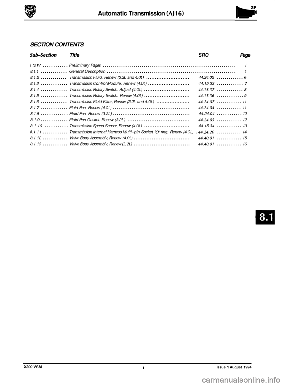
Automatic Transmission (AJ16)
SECTION CONTENTS
Subsection Title SRO Page
I to IV ............ Preliminary Pages .................................................................... i
8.1.1 ............. General Description .................................................................. 1
8.1.2 ............. Transmission Fluid. Renew (3. 2L and 4. OL) ......................... 44.24.02 ............. 6
8.1.3 ............. Transmission Control Module. Renew (4. OL) ........................ 44.15.32 ............. 7
8.1.4 ............. Transmission Rotary Switch. Adjust (4. OL) .......................... 44.15.37 ............. 8
8.1.5
............. Transmission Rotary Switch. Renew (4.0L) .......................... 44.15.36 ............. 9
8.1.6 ............. Transmission Fluid Filter, Renew (3. 2L and 4. OL)
8.1.7 ............. Fluid Pan. Renew (4. OL) ......................................... 44.24.04 ............
8.1.8 ............. Fluid Pan. Renew (3. 2L) ......................................... 44.24.04 ............ 12
8.1.9
............. Fluid Pan Gasket. Renew (3. 2L) .................................. 44.24.05 ............ 12
8.1.10.
........... Transmission Speed Sensor, Renew (4. OL) .......................... 44.15.34 ............ 13
8.1.1 1 ............ Transmission Internal Harness Multi-pin Socket '0' ring. Renew (4. OL) . 4424.20 ............ 14
Valve Body Assembly, Renew (4. OL) ............................... 44.40.01 ............ 15
.................... 44.24.07 ............ 11
11
8.1.12 ............
8.1.13 ............ Valve Body Assembly, Renew (3.2L) ............................... 44.40.01 ............ 16
X300 VSM i Issue 1 August 1994