Page 161 of 521

Automatic Transmission (V12 & AJ16 Supercharged) Powertrain
8.2.3
SRO 44.15.39
. Open the hood and fit a suitable fender cover.
9 Raise the vehicle on a ramp.
. Drain the transmission lubrication system, see Subsec-
. Remove the fluid pan, see Sub-section 8.2.14 (4,OL SC) or
. Remove the fluid filter, see Sub-section 8.2.18.
Disconnect the internal harness plug from the pressure
Release and remove the pressure switch manifold to valve
. Remove the manifold from the valve body.
. Retrieve the manifold to valve body '0' ring seals (Fig.1)
Clean the valve body manifold seating area.
. Fit new '0' ring seals to the grooves in a new pressure
Fit the manifold to the valve body.
. Fit and tighten the manifold to valve body securing bolts.
Connect the internal harness plug to the pressure switch
Refit the fluid filter, see Sub-section 8.2.18.
Refit the fluid pan, see Sub-section 8.2.14 (4,OL SC) or
. Lower the vehicle on the ramp.
. Refill the transmission unit with fluid, see Sub-section
. Remove the fender cover and close the hood.
PRESSURE SWITCH MANIFOL D, RENEW
(4,OL SC AND 6,OL)
tion 8.2.13.
Sub
-section 8.2.15 (6,OL).
switch manifold.
body securing bolts.
and discard.
switch manifold.
manifold.
Sub
-section 8.2.15 (6,OL).
8.2.13. Fig.
1
Issue 1 August 1994 6 X300 VSM
Page 162 of 521

Powertraln Automatic Transmission (V12 & AJ16 Supercharged)
8.2.4 INPUT SPEED SENSOR, RENEW (4,OL SC)
SRO 44.15.40
. Raise
the vehicle on a ramp.
Reposition the edge of the transmission tunnel sound in- sulation foam for access.
. Disconnect the harness plug from the input speed sensor.
Release and remove the speed sensor securing bolt.
. Reposition the speed sensor protection cover for access;
. Remove the speed sensor from the transmission unit and
. Clean the main case speed sensor area.
. Fit a new '0' ring seal to a new input speed sensor.
9 Lubricate the '0' ring seal.
. Fit and seat the speed sensor to the main case.
. Reposition and align the speed sensor protection cover.
. Fit and tighten the speed sensor securing bolt.
Connect the harness plug to the speed sensor.
Reposition the edge of the transmission tunnel sound in-
. Lower the vehicle on the ramp.
the
cover remains captive on the harness.
place aside. @ sulation foam to the original position.
8.2.5
SRO 44.15.41
. Raise the vehicle on a ramp.
. Reposition the edge of the transmission tunnel sound in- sulation foam for access.
. Disconnect the harness plug from the output speed sen-
sor.
. Release and remove the speed sensor securing bolt.
. Reposition the speed sensor protection cover for access,
noting that the cover remains captive on the harness.
. Remove the speed sensor from the transmission unit and
place aside.
. Clean the main case speed sensor area.
. Fit a new '0 ring seal to a new output speed sensor.
. Lubricate the '0 ring seal.
. Fit and seat the speed sensor to the main case.
. Reposition and align the speed sensor protection cover.
Fit and tighten the speed sensor securing bolt.
. Connect the harness plug to the speed sensor.
Reposition the edge of the transmission tunnel sound in-
. Lower the vehicle on the ramp.
OUTPUT SPEED SENSOR, RENEW (4,OL SC)
sulation foam to the original position.
X300 VSM 7 Issue 1 August 1994
Page 163 of 521

Automatic Transmission (V12 & AJ16 Supercharged) Powertrain
8.2.6
SRO 44.15.40
. Open the hood and fit a suitable fender cover.
. Raise the vehicle on a ramp.
. Slacken the underfloor catalyst to downpipe clamps se-
. Displace and reposition the olive clamps on the pipes.
INPUT SPEED SENSOR, RENEW (6,OL)
curing bolts.
Slacken the underfloor catalyst
to intermediate silencer
clamps securing bolts.
9 Displace the underfloor catalyst assembly rearwards to
disconnect from the downpipes.
Displace and remove the olives from the downpipes.
Using a wire brush, clean the olives and downpipe joints.
. Place a suitable piece of wood between the underfloor
. Reposition the edge of the transmission tunnel insulation
. Release and remove the input speed sensor securing bolt.
. Reposition the speed sensor protection cover for access,
noting that the cover remains captive on the harness.
Disconnect the speed sensor harness multi
-pin plug.
- Displace and remove the speed sensor from the trans- mission case.
Clean the transmission case area.
. Fit a new ‘0 ring seal to a new input speed sensor.
. Lubricate the ‘0 ring seal.
. Fit and fully seat the speed sensor to the transmission
. Reconnect the harness multi-pin plug.
Reposition and align the protection cover.
. Fit and tighten the speed sensor securing bolt.
Reposition the insulation foam to its original position.
Remove the block of wood from between the underfloor
. Apply sealant to the downpipe joints and olives. See Ser-
Fit and seat the olives to the downpipes.
Reposition the olive clamps.
Tighten the underfloor catalyst to downpipe clamps secur-
Align the intermediate silencers to the underfloor catalyst
. Tighten the clamp securing bolts.
. Lower the vehicle on the ramp.
Remove the fender cover and close the hood.
catalyst
and the body for access.
foam for access.
0
case.
catalyst and the floor.
vice Materials
in the preliminary pages, this Section.
Reconnect the underfloor catalyst to the downpipes.
0
ing bolts.
assembly.
lppl
0
X300 VSM issue 1 August 1994 8
Page 164 of 521

Powertwin Automatic Transmission (V12 & AJ16 Supercharged)
8.2.7
SRO 44.15.41
OUTPUT SPEED SENSOR, RENEW (6,OL)
. Open the hood and fit a suitable fender cover.
. Raise the vehicle on a ramp.
. Slacken the underfloor catalyst to downpipe clamps se-
Displace and reposition the olive clamps on the pipes.
. Slacken the underfloor catalyst to intermediate silencer
. Displace the underfloor catalyst assembly rearwards to
. Displace and remove the olives from the downpipes.
. Using a wire brush, clean the olives and downpipe joints.
Place a suitable piece of wood between the underfloor
catalyst and the body for access.
. Reposition the edge of the transmission tunnel insulation
foam for access.
. Release and remove the output speed sensor securing
bolt.
Reposition the speed sensor protection cover for access,
noting that the cover remains captive on the harness.
. Disconnect the speed sensor harness multi-pin plug.
. Displace and remove the speed sensor from the trans-
. Clean the transmission case sensor area.
. Fit a new '0' ring seal to a new output speed sensor.
. Lubricate the '0' ring seal.
Fit and fully seat the speed sensor to the transmission
. Reconnect the harness multi-pin plug.
Reposition and align the protection cover.
. Fit and tighten the speed sensor securing bolt.
Reposition the insulation foam to its original position.
Remove the block of wood from between the underfloor
catalyst and the floor.
. Apply sealant to the downpipe joints and olives. See Ser- vice Materials in the preliminary pages, this Section.
. Fit and seat the olives to the downpipes.
. Reconnect the underfloor catalyst to the downpipes.
= Reposition the olive clamps.
. Tighten the underfloor catalyst to downpipe clamps secur-
= Align the intermediate silencers to the underfloor catalyst
. Tighten the clamp securing bolts.
Lower the vehicle on the ramp.
. Remove the fender cover and close the hood.
curing
bolts.
cl amps securing bolts.
disconnect from the downpipes.
mission case.
case.
0
ing bolts.
assembly.
Issue 1 August 1994 X300 VSM 9
Page 165 of 521

Automatic Transmission (V12 & AJ16 Supercharged) Powertrain
8.2.8 TEMPERATURE SENSOR, RENEW
(4,OL SC AND 6,011
The temperature sensor forms part of the internal wiring
harness. Should the sensor require replacement, a new wir- ing harness must be fitted. See Subsection 8.2.2.
8.2.9 VARIABLE FORCE MOTOR, RENEW
SRO 44.15.43
. Open the hood and fit a suitable fender cover.
. Raise the vehicle on a ramp.
. Drain the transmission lubrication system, see Sub-sec-
Remove the fluid pan, see Sub-section 8.2.14 (4,OL SC) or
Remove the fluid filter, see Subsection 8.2.18.
Disconnect the internal harness plug from the variable
Release and remove the motor retaining clamp to valve
. Remove the retaining clamp (2 Fig.1) and remove the
Fit a new variable force motor to the valve body.
CAUTIOI\I: Do not adjust the motor screw and ensure that
the motor filter is not damaged.
. Align the motor.
. Fit the motor to the valve body retaining clamp.
. Fit and tighten the motor retaining clamp securing screw.
Connect the internal harness
plug to the motor.
. Refit the fluid filter, see Sub-section 8.2.18.
. Refit the fluid pan, see Subsection 8.2.14 (4,OL SC) or
. Lower the vehicle on the ramp.
. Refill the transmission unit with fluid, see Subsection
(4,OL SC AND 6,011
tion 8.2.13.
Sub
-section 8.2.15 (6,OL).
force motor.
body securing screw (1
Fig.1).
motor (3 Fig.1) from the valve body and place aside.
Sub
-section 8.2.15 (6,OL).
8.2.13.
m Remove the fender cover and close the hood.
JU 596
Fig. 1
X300 VSM Issue 1 August 1994 10
Page 166 of 521

Powortrain Automatic Transmission (V12 & AJl6 Supercharged)
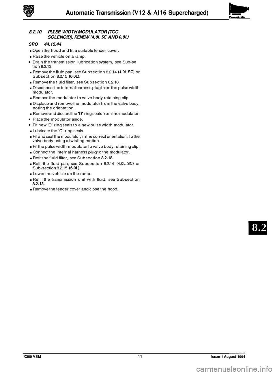
8.2.10 PULSE WIDTH MODULATOR (TCC
SRO 44.15.44
. Open the hood and fit a suitable fender cover.
. Raise the vehicle on a ramp.
Drain the transmission lubrication system, see Sub-se
. Remove the fluid pan, see Subsection 8.2.14 (4,OL SC) or
. Remove the fluid filter, see Subsection 8.2.18.
. Disconnect the internal harness plug from the pulse width
. Remove the modulator to valve body retaining clip.
. Displace and remove the modulator from the valve body,
. Remove and discard the '0' ring seals from the modulator.
Place the modulator aside.
Fit new '0' ring seals to a new pulse width modulator.
. Lubricate the '0' ring seals.
. Fit and seat the modulator, in the correct orientation, to the
. Fit the pulse width modulator to valve body retaining clip.
. Connect the internal harness plug to the modulator.
. Refit the fluid filter, see Subsection 8.2.18.
. Refit the fluid pan, see Subsection 8.2.14 (4,OL SC) or
. Lower the vehicle on the ramp.
. Refill the transmission unit with fluid, see Subsection 8.2.13.
. Remove the fender cover and close the hood.
SOLENOID), RENEW (4,OL SC AND 6,OL) a
tion 8.2.13.
Subsection 8.2.15
(6,OL).
modulator.
noting the orientation.
valve body using a twisting motion.
Sub
-section 8.2.15 (6,OL).
X300 VSM 11 Issue 1 August 1994
Page 167 of 521

Automatic Transmission (V12 & AJ16 Supercharged)
8.2.11 'A' SHIFT SOLENOID, RENEW
(4,Ol SC AND 6,OL)
SRO 44.15.45
Open the hood and fit a suitable fender cover.
Raise the vehicle on a ramp.
. Drain the transmission lubrication system, see Sub-sec-
Remove the fluid pan, see Sub-section 8.2.14 (4,OL SC) or
= Disconnect the internal harness plug from the 'A' Shift
. Release and remove the 'A' Shift solenoid to valve body
. Remove the solenoid from the valve body (Fig. 1).
= Remove and discard the '0' ring seal from the valve body.
. Place the solenoid aside.
. Fit a new '0 ring seal to a new 'A' Shift solenoid.
. Lubricate the '0' ring seal.
Fit the solenoid to the valve body using a twisting motion.
. Fit and tighten the solenoid to the valve body using a new
. Connect the internal harness plug to the solenoid.
. Refit the fluid pan, see Sub-section 8.2.14 (4,OL SC) or
. Lower the vehicle on the ramp.
. Refill the transmission unit with fluid, see Sub-section
Remove the fender cover and close the hood.
tion
8.2.13.
Sub
-section 8.2.15 (6,OL).
solenoid.
securing screw.
securing screw.
Sub
-section 8.2.15 (6,OL).
8.2.13.
Fin. 1
Issue 1 August 1994 12 X300 VSM
Page 168 of 521

Pomrtrain Automatic Transmission (V12 & AJ16 Supercharged)
8.2.12 '6' SHIFT SOLENOID, RENEW
(4,OL SC AND 6,OL)
SRO 44.15.46
Open the hood and fit a suitable fender cover.
. Raise the vehicle on a ramp.
. Drain the transmission lubrication system, see Sub-sec-
. Remove the fluid pan, see Subsection 8.2.14 (4,OL SC) or
. Disconnect the internal harness plug from the 'B' Shift
. Release and remove the 'B' Shift solenoid to valve body
. Remove the solenoid from the valve body (Fig. 1).
. Remove and discard the '0' ring seal from the solenoid.
= Place the solenoid aside.
. Fit a new '0' ring seal to a new 'B' Shift solenoid.
. Lubricate the '0' ring seal.
. Fit the solenoid to thevalve body using a twisting motion.
. Fit and tighten the solenoid to the valve body using a new
. Connect the internal harness plug to the solenoid.
. Refit the fluid pan, see Subsection 8.2.14 (4,OL SC) or
Lower the vehicle on the ramp.
Refill the transmission unit with fluid, see Subsection
8.2.13.
= Remove the fender cover and close the hood.
tion
8.2.13.
Subsection 8.2.15
(6,OL).
solenoid.
securing screw.
securing screw.
Sub
-section 8.2.15 (6,OL).
Fig. 1
X300 VSM 13 Issue 1 August 1994