Page 265 of 521

Body Components & Trim -
13.3.2
SRO 76.25.01/50
. Remove the console rear extension finisher, see sub-sec-
. Remove the console rear extension veneer panel, see sub-
. Remove the console rear extension, see sub-section
. Remove the drivers side underscuttle pad, see sub-sec-
. Remove the passenger side underscuttle pad, see sub-
. Remove the console ashtray, see sub-section 13.3.28.
. Remove the console finisher veneer panel, see sub-sec-
. Remove the radio console, see sub-section 13.3.10.
Remove the fascia center veneer panel, see sub-section
Undo and remove the console upper securing screws.
. Displace and reposition the rear air distribution outlet box.
. Disconnect the cigar lighter multi-plug (where fitted).
. Disconnect the security system valet switch harness
multi
-plug.
. Remove the air distribution outlet box.
9 Undo and remove the center console rear mounting secur- ing screw.
. Displace and remove the console assembly and place on
the bench.
. Displace and remove the spire clips from the console as- sembly.
. Open the glove box lid.
. Remove the glove box lid latch.
. Undo and remove the glove box lid rear securing screws.
. Displace and remove the glove box lid /glove box assem- bly.
. Place the console aside.
. Place the new console to the front.
. Fit and align the glove box lid /glove box assembly.
. Fit but do not fully tighten the glove box lid securing screw.
. Close the glove box lid and check the adjustment.
. Open and adjust the lid.
. Finally tighten the securing screws.
. Fit and align the glove box lid latch.
. Close the glove box lid.
. Fit and align the spire clips to the console.
Console Assembly - Renew (Daimler / VDP)
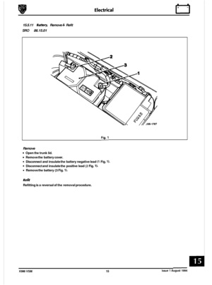
Remove the battery cover. Disconnect the battery.
tion 13.3.5.
section 13.3.27.
13.3.6.
tion 13.3.19.
section
13.3.20.
tion 13.3.24.
13.3.23.
Issue 1 August 1994 10 X300 VSM
Page 266 of 521
Body Components & Trim -
. Place the console in position in the vehicle.
. Fit and tighten the front securing screws.
. Fit and tighten the rear securing screw.
. Reconnect the security system valet switch multi-plug.
= Place the air distribution outlet in position.
. Connect the rear cigar lighter harness multi-plug (where
9 Fit and fully seat the air distribution outlet.
Refit the fascia center veneer panel.
. Refit the radio console.
. Refit the console veneer panel.
. Refit the console ashtray.
. Refit the console finisher.
9 Refit the underscuttle pads.
. Refit the console extension.
. Refit the console extension veneer panel.
. Refit the console rear extension finishe.
. Reconnect the batten/. Refit the battery cover.
fitted).
Issue 1 August 1994 X300 VSM 11
Page 267 of 521

Body Components & Trim
0 13.3.3
SRO 76.25.01/91
. Remove the battery cover. Disconnect the battery.
. Remove the console rear extension finisher, see sub-sec-
8 Remove the console rear extension veneer panel, see sub-
. Remove the console rear extension, see sub-section
. Remove the drivers side underscuttle pad, see sub-sec-
. Remove the passenger side underscuttle pad, see sub-
. Remove the console ashtray, see sub-section 13.3.28.
. Remove the console finisher veneer panel, see sub-sec-
. Remove the radio console, see sub-section 13.3.10.
. Remove the fascia center veneer panel, see sub-section 13.2.23.
Undo and remove the console upper securing screws.
. Displace and reposition the rear air distribution outlet box.
. Disconnect the cigar lighter multi-plug (where fitted).
. Disconnect the security system valet switch harness
multi
-plug.
. Remove the air distribution outlet box.
. Undo and remove the center console rear mounting secur-
ing screw.
. Displace and remove the console assembly and place on
the bench.
. Place the console in position in the vehicle.
. Fit and tighten the front securing screws.
. Fit and tighten the rear securing screw.
. Reconnect the security system valet switch multi-plug.
Place the air distribution outlet in position.
. Connect the rear cigar lighter harness multi-plug (where
. Fit and fully seat the air distribution outlet.
Refit the center vent veneer panel assembly.
Refit the radio console.
. Refit the console veneer panel.
. Refit the console ashtray.
. Refit the console finisher.
. Refit the underscuttle pads.
. Refit the console extension.
. Refit the console extension veneer panel.
. Refit the console rear finishe.
. Reconnect the battery. Refit the battery cover.
Console Assembly - Remove For Access And
Refit (Daimler
/ VDP)
tion 13.3.5.
section 13.3.27.
13.3.6.
tion 13.3.19.
section 13.3.20.
tion 13.3.24.
0
fitted).
0
m
0
X300 VSM Issue 1 August 1994 12
Page 268 of 521

Body Components & Trim -
0 13.3.4 Console Assembly, Renew
SRO 76.25.01
. Remove the battery cover. Disconnect the battery.
. Remove the drivers side and passenger side underscuttle
pads, see subsections 13.3.19 and 13.3.20.
Remove the console ashtray, see sub-section 13.3.28.
. Remove the console finisher veneer panel, see sub-sec-
tion 13.3.24.
. Remove the radio console, see sub-section 13.3.10.
. Remove the fascia center veneer panel, see sub-section
. Undo and remove the console upper securing screws.
. Displace and reposition the rear air distribution outlet box.
. Disconnect the cigar lighter multi-plug (where fitted).
. Disconnect the security system valet switch multi-plug.
. Remove the rear air distribution outlet box.
. Disconnect the security system valet switch multi-plug.
. Remove the rear air distribution outlet box.
. Undo and remove the center console rear mounting secur- ing screw.
. Remove the console assembly and place on the bench.
. Displace and remove spire clips from console assembly.
. Open the glove box lid.
. Remove the glove box lid latch.
Undo and remove glove box lid rear securing screws.
Displace and remove glove box lid / glove box assembly.
. Place the console aside.
Place the new console to the front.
. Fit and align the glove box lid /glove box assembly.
. Fit but do not fully tighten the glove box lid securing screw.
. Close the glove box lid and check the adjustment.
Open and adjust the glove box
lid.
. Finally tighten the lid securing screws.
. Fit and align the glove box lid latch.
. Close the glove box lid.
. Fit and align the spire clips to the console.
. Place the console in position in the vehicle.
. Fit and tighten the console front securing screws.
Fit and tighten the console rear securing screw.
. Reconnect the security system valet switch multi-plug.
. Place the air distribution outlet in position.
Connect rear cigar lighter harness multi-plug (if fitted).
Fit and fully seat the air distribution outlet.
. Refit fascia center veneer panel.
Refit the radio console.
. Refit the console finisher veneer panel.
. Refit the console ashtray.
9 Refit underscuttles.
. Reconnect the battery.
. Refit the battery cover.
13.3.23.
Issue 1 August 1994 X300 VSM 13
Page 269 of 521

Body Components & Trim -
13.3.5
SRO 76.25.04
. Carefully displace and remove the motif from the exten-
. Undo and remove the finisher securing screw.
. Displace and remove the finisher.
Fit and seat the new finisher to the extension.
. Fit and tighten the finisher securing screw.
. Apply suitable adhesive to the back of the motif.
. Fit and seat the motif to the finisher.
Console Rear Extension Finisher, Renew
sion finisher (Fig. 1).
13.3.6 Console Rear Extension, Renew
SRO 76.25.05
Remove the console rear extension finisher, see sub-sec-
. Remove the console rear extension veneer panel, seesub-
. Undo and remove the extension securing screws.
. Displace and remove the extension assembly.
Remove the screw and peg inserts.
. Place the extension aside.
. Place the new extension to the front.
. Fit the screw and peg inserts.
. Fit and align the extension assembly to the floor.
. Fit and tighten the extension securing screws.
9 Refit the rear extension veneer panel.
Refit the rear extension finisher.
tion
13.3.5 above
and Fig. 1.
section 13.3.27.
13.3.7
SRO 76.25.07
. Carefully displace and remove the gearshift aperture plas-
rn Displace and remove the selector trim finisher.
= Fit and fully seat the new selector trim finisher.
. Fit and fully seat the gearshift aperture plastic finisher.
Selector Trim Finisher, Renew (3.2 liter)
tic finisher, Fig. 2. Fia.
1
Fig.
2
Issue 1 August 1994 14 X300 VSM
Page 270 of 521
Body Components & Trim
13.3.8 Selector Trim Finisher, Renew (4.0 Liter, 4.0 Liter
SCAnd 6.0 Liter)
SRO 76.25.07
Remove the mode switch (Fig. 1).
Remove the mode switch finisher (Fig. 2).
Displace and remove the selector trim finisher.
Refit the mode switch finisher.
Refit the mode switch.
13.3.9 Mode Switch Finisher, Renew
SRO 76.25.09
Remove the mode switch (Fig. 1).
Carefully displace and remove the finisher (Fig. 21..
. Fit and fully seat the new finisher.
Refit the mode switch. Fig.
1
Fig. 2
Issue 1 August 1994 X300 VSM 15
Page 271 of 521

Body Components & Trim e
Remove the battery cover. Disconnect the battery.
. Remove the console ashtray, see subsection 13.3.28.
. Remove console veneer panel, see subsection 13.3.24.
. Remove the gear selector ident plate securing screws.
. Carefully reposition the radio console assembly from the
mounted position.
. Disconnect the assembly harness multi-plugs.
. Disconnect the antenna co-axial connector.
Undo and remove the ground lead to radio securing nut.
. Reposition the ground lead from radio stud.
. Disconnect the radio harness multi-plugs.
. Reposition the radio harness from the center console.
. Displace the radio console assembly.
. Remove the radio assembly from the console.
. Remove the radio retaining plate.
Undo and remove the air conditioning control module se
-
curing screws.
. Displace and remove the module.
. Undo and remove switch/clock module securing screws.
. Displace and remove the module assembly.
. Place the radio console aside.
. Place the new radio console to the front.
. Fit and fully seat the switch /clock module to the console.
. Fit and tighten the module securing screws.
. Fit and fully seat air conditioning module to the console.
. Fit and tighten the securing screws.
. Fit and fully seat the radio mounting plate to the console.
. Place the radio console to the center console position.
. Place the radio to the center console position.
* Route the radio harness / multi-plugs through the radio
. Connect the radio harness multi-plugs.
8 Connect the radio console harness multi-plugs.
. Route the radio ground and antenna leads through the
. Fully seat the radio console in the mounted position.
Reposition the ground lead to radio securing stud.
Fit and tighten the securing nut.
Connect the antenna co-axial to the radio.
. Reposition the excess harness / leads into the radio
mounting hole, ensuring that the harnesses are posi- tioned to allow the radio to be pushed fully home.
console
into the center console position.
radio console.
Fit and tighten the securing screws.
. Fully seat the radio into the console.
. Reposition and fit the selector ident plate.
. Fit and tighten the ident plate securing screws.
. Refit the console veneer panel. I
13.3.10 Radio Console, Renew
SRO
76.25.15
Issue 1 August 1994 16 X300 VSM
Page 272 of 521

Body Components & Trim
13.3.11 Console Glove Box, Renew
SRO
76.25.16
. Remove the console glove box lid, see subsection
= Undo and remove the glove box/ ashtray securing screws.
. Carefully displace the ashtray upwards for access.
. Displace and remove the ashtray lid catch.
. Displace and reposition the glove box assembly.
. Disconnect the security valet switch harness multi-plug.
. Remove the glove box.
. Displace and remove the valet switch.
. Displace and remove the glove box lid checkarm.
Place the glove box aside.
. Place the new glove box to the front.
. Fit and fully seat the checkarm guide to the glove box.
. Fit and align the checkarm to the glove box.
. Fit and fully seat the valet switch to the glove box.
. Align and affix a security sticker to the glove box.
= Align and affix a cassette storage foam pad.
Place the glove box assembly into position.
. Reconnect the valet switch harness multi-plug.
. Fit and fully seat the glove box assembly.
. Fit and align the lid latch.
. Reposition and fit the ashtray.
. Fit and tighten the ashtray securing screws.
. Refit the glove box lid.
13.3.12.
Place the glove box to the front.
Displace and remove the glove box
lid checkarm guide.
Issue 1 August 1994 X300 VSM 17