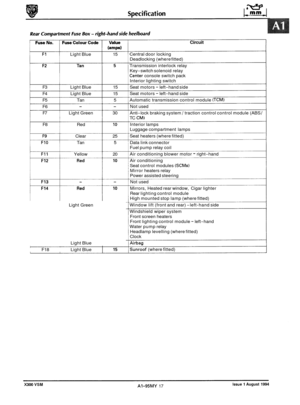
Page 241 of 521

12.3 BRAKE FLUID LEVEL CHECK
WARNING: AVOID SKIN / EYE CONTACT OR INGESTION OF BRAKE FLUID. IF SKIN OR EYES ARE ACCIDENTALLY
SPLASHED WITH BRAKE FLUID, RINSE THE AFFECTED AREA IMMEDIATELY WITH PLENTY OF WATER
AND SEEK MEDICAL AlTENTlON IMMEDIATELY.
Checking the fluid level
CAUTION: Fluid must not be allowed to contact the vehicle paintwork. Remove any spilt fluid from the paintwork
by rinsing away with running water. Methylated spirit (denatured alcohol) must not be used to clean the contaminated area.
Correct brake fluid level is essential for the efficient oper- ation of the brake system. Check that the fluid level is be- tween the MAXand MIN marks on the fluid reservoir (Fig. 1). Top up if necessary with recommended brake fluid.
BMQ: The efficiency of the brakes may be impaired if fluid
is used which does not meet specifications. Use
ONLY brake and clutch fluid that conforms to
a mini- mum DOT 4 specification. Also do not use brake
fluid that has been exposed to atmosphere for any
length of time. Moisture absorbed from the atmos
- phere impairs the efficiency of the brake fluid.
JLX- 081
Fig. 1
Issue 1 August 1994 18 X300 VSM
Page 242 of 521

Brakes
12.4 BRAKE SYSTEM BLEEDING
WAR-: GREAT CARE MUST BE EXERCISED WHEN SERVICING OR REPAIRING THE SYSTEM. AVOID SKIN/ EYE
CONTACT OR INGESTION OF BRAKE FLUID. IF SKIN OR EYES ARE ACCIDENTALLY SPLASHED WITH
BRAKE FLUID,
RINSETHE AFFECTED AREA IMMEDIATELY WITH PLENTY OF WATER AND SEEK MEDICAL
ATTENTION. IF BRAKE FLUID IS INGESTED, SEEK MEDICAL ATTENTION IMMEDIATELY.
CAUm: Fluid must not be allowed to contact the vehicle paintwork. Remove any spilt fluid from the paintwork
by rinsing away with running water. Methylated spirit (denatured alcohol) must not be used to clean the
contaminated area.
CAUTION: Never use methylated spirit (denatured alcohol) for component cleaning purposes. Use only a proprietary
brake cleaning fluid.
WARNING : THROUGHOUT THE FOLLOWING MAINTENANCE / SERVICE OPERATIONS, ABSOLUTE CLEANLINESS
MUST BE OBSERVED TO PREVENT FOREIGN MATTER CONTAMINATING THE BRAKE SYSTEM.
12.4.1 System Bleeding - General Instructions
Use a brake bleeder bottle with a clear bleeder tube. Also recommended is a filler unit with a fill pressure of 1.0 bar. If a filler unit is not used, ensure that their is sufficient brake fluid in the reservoir throughout the bleeding procedure.
m: Always bleed the caliper furthest away from the actuation unit first. On right hand drive vehicles, bleed in the
following order: front
left (FL),front right (FR), rear left (RL) and rear right (RR). On left hand drive vehicles bleed in the following order: FR, FL, RR and RL.
12.4.2
. Ensure that the vehicle is standing level. Switch the igni-
tion off.
Check that the fluid level in the reservoir is between the min and max marks.
. Connect the bleeder bottle tube to the relevant front cali- per (see'note' above) bleeder screw (1 Fig. 1) and open the
screw.
rn Bleed until new, clear, bubble free fluid is observed in the
tube and then close the bleeder screw.
. Repeat this procedure at each remaining caliper.
With the motorrunning check brake pedal travel.
If excess- ive, check for leaks and repeat the bleed procedure.
Fill the reservoir to the max level.
System Bleeding After Brake Fluid Renewal
12.4.3 System Bleeding After Tandem Master Cylinder
Renewal
Ensure that the vehicle is standing level. Switch the igni- tion off.
rn Check that the fluid level in the reservoir is between the min and max marks.
Connect the bleeder bottle tube to the relevant front cali- per (see'note'above) bleederscrew(1 Fig. 1) and open the
screw.
Ficr. 1
X300 VSM 19 Issue 1 August 1994
Page 243 of 521

. Actuate the brake pedal to the floor, hold for approximately two seconds and then release the pedal. Wait another two seconds and actuate the brake pedal again for a further two seconds. Repeat this action 20 to 30 times until clear,
bubble free brake fluid streams out.
. With the brake pedal actuated, close the bleeder screw. Build up fluid pressure by pumping the pedal and then open
the bleeder screw. Repeat this action three to five times.
If a filler unit is not used, observe the fluid level in the reservoir and top up if necessary.
. Repeat this procedure for the remaining three calipers. (1 Fig. 1) shows the bleeder screw of the rear left caliper.
. With the motor running check brake pedal travel. If excess- ive, check for leaks and repeat the bleed procedure.
. Fill the reservoir to the max level.
12.4.4
Hydraulic control modules are supplied pre-filled to enable
the brake system to be bled in the conventional way.
. Ensure that the vehicle is standing level. Switch the igni- tion off.
. Check that the fluid level in the reservoir is between the
min and max marks.
Connect the bleeder bottle tube to the relevant front cali- per (see 'note' on previous page) bleeder screw (1 Fig. 1) and open the screw.
. Actuate the brake pedal full stroke, wait a moment and
then release. Wait two to three seconds and then actuate
the brake pedal full stroke again. This allows the TMC to
be completely re
-filled with fluid.
. Repeat 20 to 30 times until the fluid in the bleeder tube is
clear and bubble free.
System Bleeding After Hydraulic Control
Module Renewal
I J70 -209
Fig. 1
With the brake pedal actuated, close the bleeder screw. Build up fluid pressure by pumping the pedal and then open
the bleeder screw. Repeat this action three times.
w: If a filler unit is not used, observe the fluid level in the reservoir and top up if necessary.
. Repeat this procedure for the remaining three calipers.
. With the motor running check brake pedal travel. If pedal travel is excessive, check the system for leaks and repeat
Fill the reservoir to the max level.
the
bleed procedure.
12.4.5
Follow the procedure above but only at the affected caliper.
Bleeding After Renewal of Caliper
Issue 1 August 1994 20 X300 VSM
Page 244 of 521

Brakes
a 12.5 GENERAL FI77lNG lNSTRUCTlONS
12.5.1 Brake Fluid
WARNING: BRAKE FLUID IS CORROSIVE. EXTREME CARE MUST BE TAKEN WHEN HANDLING. AVOID SKIN OR EYE
CONTACT. AVOID INGESTION. IF SKIN OR EYES ARE ACCIDENTALLY SPLASHED WITH BRAKE FLUID,
RINSE THE AFFECTED AREA IMMEDIATELY WITH PLENTY OF WATER AND SEEK MEDICAL ATTENTION.
IF BRAKE FLUID
IS INGESTED, SEEK MEDICAL ATTENTION IMMEDIATELY.
CAUTION:
Fluid must not be allowed to contact the vehicle paintwork. Remove any spilt fluid from the paintwork
by rinsing away with running water. Methylated spirit (denatured alcohol) must not be used to clean the
contaminated area.
Cleaning Solvents
CAUTION: Never use methylated spirit (denatured alcohol) for cleaning purposes. Use only a proprietary brake
cleaning fluid.
m: THROUGHOUT THE FOLLOWING MAINTENANCE / SERVICE OPERATIONS, ABSOLUTE CLEANLINESS
MUST BE OBSERVED TO PREVENT GRIT OR OTHER FOREIGN MATTER CONTAMINATING THE BRAKE
TION. TO CLEAN BRAKE SYSTEM COMPONENTS, WASH
IN A PROPRIETARY BRAKE CLEANING FLUID.
REMOVE ALL TRACES OF CLEANING FLUID BEFORE REASSEMBLY. ALL BRAKE SYSTEM RUBBER COh PONENTS MUST BE DIPPED IN CLEAN BRAKE FLUID AND ASSEMBLED USING THE FINGERS ONLY.
SYSTEM.
IFTHE SYSTEM IS TO
BE FLUSHED, USE CLEAN BRAKE FLUID TO MINIMUM DOT 4 SPECIFICA-
12.5.2 Hoses
Fully release the unions (1 Fig. 1) securing each end of the
hose to the fluid pipes. Withdraw the pipe unions (1 Fig. 1) from the hose ends.
Plug the ends of the pipes (2 Fig. 1) to prevent the loss of
fluid and the ingress of dirt.
Remove the mounting bracket locknut (3 Fig. 1) and re- move the hose (4 Fig. 1).
Thoroughly clean the hose and examine for any signs of
wear or damage. Renew the hose if there is any doubt
about its condition. Thoroughly clean the bore of the hose
using compressed air.
. Remove all blanking plugs and fit the new hose to the cali- per / connector. Secure the hose to the mounting bracket.
. Before fully tightening the locknut, ensure that the hose is
neither kinked nor twisted.
. Bleed the brakes.
12.5.3 Pipes
. Fully release the pipe unions (1 Fig. 1).
. Withdraw the pipe (5 Fig. 1) from the vehicle. Plug the
pipes (2 Fig. 1) to prevent the loss of fluid or the ingress of dirt. Thoroughly clean and examine the pipe for signs of damage or deterioration. Renew the pipe if there is any
doubt about its condition.
Thoroughly clean the bore of the pipe using compressed
air.
. Remove all blanking plugs and fit the new pipe to the ve- hicle. Secure the pipe to the body.
. Bleed the brakes.
17
Fig. 1
X300 VSM 21 Issue 1 August 1994
Page 245 of 521

12.6 REAR WHEEL SPEED SENSOR - RENEW
SRO
70.60.04
. Drive the vehicle onto a ramp or raise the back and support
on two stands.
. Cut and remove the ratchet strap securing the speed sen- sor harness to the brake hose.
. Undo and remove the speed sensor to hub carrier secur- ing bolt (Fig. 1).
Remove the speed sensor from the hub carrier and allow
it to hang free, forward of the 'A' frame.
Open both rear doors and displace the rear seat cushion
from the seat pan brackets. Reposition the rear seat
cushion forwards.
9 Push the seat belts/ buckles through the seat cushion slots
and remove the rear seat cushion from the vehicle.
. Displace the RH side of the seat pan sound proofing (1 Fig. 2) to gain access to the speed sensor harness (2 Fig. 2).
9 Displace the speed sensor harness grommet (3 Fig. 2) from the seat pan aperture.
. Feed the speed sensor harness through the seat pan aper- ture and disconnect the multi-plug (4 Fig. 2).
9 Position the new speed sensor harness and connect the
multi-plug.
. Feed the speed sensor harness through the seat pan aper- ture to hang free below the vehicle.
. Refit and fully seat the speed sensor harness grommet to
the seat pan aperture.
Reposition theseat pan sound proofing to its original posi- tion.
Position the rear seat cushion and feed the seat belt / buckles through the slots.
Locate the rear seat cushion into the seat pan brackets (5 Fig. 2).
. Stow the seat belts / buckles.
. Position the speed sensor harness rearwards over the 'A'
Fit and tighten the speed sensor to hub carrier securing
Secure the speed sensor harness to the brake hose using
frame
and locate into the hub carrier.
bolt.
a ratchet strap. Trim the ratchet strap. Fig.
1
Fig. 2
Issue 1 August 1994 22 X300 VSM
0
0
0
Page 246 of 521

Brakes
12.7 HYDRAULICCONTROL MODULE- RENEW
SRO 70.60.18
70.60.1
9
Refer to Section 12.4, Brake System Bleeding before carrying out this procedure. Pay particular attention to the warn- ings and cautions relating to brake fluid, cleanliness and cleaning materials.
W: The illustration shows the hydraulic control module of a 6 cyl. vehicle with traction control. Hydraulic control
modules on non-traction control vehicles have only three outlet ports. Apart from this, the removal procedure
is the same for all vehicles.
. Raise the vehicle.
Displace the bleeder screw dust cap of the front LH caliper.
The dust cap will remain captive
on the bleed screw.
. Connect a bleeder tube and bottle to the bleeder screw (1
Fig. 1) and open the bleeder screw.
. Fit a brake pedal hold-down tool (JDS-9013) between the
brake pedal and the steering wheel. Adjust the tool to op
- erate the brake pedal 60mm down. This operation is
necessary to prevent fluid loss from the reservoirthrough
. Re-tighten the front LH caliper bleeder screw. Disconnect
the bleeder tube from the bleeder screw and remove the
tube and bottle. Refit the bleeder screw dust cap.
Undo the securing bolt of the multi-plug connector (1 Fig. 2). The bolt will remain captive. Disconnect the multi-plug
connector and reposition safely.
. Place absorbent material underneath the hydraulic con-
trol module to absorb any spillages.
Undo the tandem master cylinder CTMC) brake pipe gland
nuts (2 Fig.2) and disconnect the brake pipes.
. Fit plugs immediately to the brake pipes and the hydraulic
control module to prevent fluid
loss.
. Undo the rear brake pipe gland nuts (3 Fig. 2) at the pres- sure conscious reducing valves (PCRVs) (4 Fig. 2). Remove
the rear brake pipes.
disconnected brake pipes.
Note: Take necessary steps to prevent rotation of the
PCRVs when removing the rear brake pipes.
Fit plugs immediately to the brake pipes and the PCRVs to
. Undo and remove the PCRVs. Fit plugs immediately to the
Place PCRVs aside to be fitted later to the new hydraulic
. Undo the front brake pipe gland nuts (5 Fig. 2) and remove
. Fit plugs immediately to the brake pipes and the hydraulic
. Undo and remove the three securing nuts (6 Fig. 2) and re-
0 prevent fluid loss.
PCRVs and the hydraulic control module.
control module.
the front brake pipes.
control module to prevent fluid
loss.
move the hydraulic control module. Fia.
1
3 1 J70 296
Fia. 2
Issue 1 August 1994 X300 VSM 23
Page 247 of 521

Remove the absorbent material and clean the mounting bracket and surrounding area.
Fit and align a new hydraulic control module to the mounting bracket. Ensure that the mounting cup tangs fully en-
9 Fit and tighten the securing nuts (6 Fig. 1).
. Place absorbent material underneath the hydraulic con- trol module to absorb any spillages.
. Connect the front hydraulic brake pipes (5 Fig. 1) tothe hy- drauliccontrol module, removing plugs immediately prior
to connection. Tighten the gland nuts.
Fit the PCRVs (4 Fig. 1) to the hydrauliccontrol module, re- moving plugs immediately prior to connection. Tighten
the PCRVs.
Connect the rear hydraulic brake pipes (3 Fig. 1) to the
PCRVs, removing the plugs immediately prior to connec- tion. Tighten the gland nuts.
gage
the bracket slots.
&&a: Take necessary steps to prevent rotation of the
PCRVs when fitting the rear brake pipes.
Connect
theTMC hydraulic brake pipes (2 Fig. 1) to the hy- draulic control module, removing the plugs immediately
prior to connection. Tighten the gland nuts.
. Remove the absorbent material and clean thesurrounding
area.
. Reposition and connect the multi-plug connector. Tighten
the securing bolt (1 Fig. 1).
. Ensure that all fixings are torque tightened to specified tol- erances.
. Release the brake pedal hold-down tool and remove.
. Bleed the brake system (refer to sub-section 12.4.4).
. Examine the hydraulic control module for leaks.
3 1 J70 296
Fig. 1
Issue 1 August 1994 ~~ X300 VSM
Page 248 of 521

Brakes
12.8
SRO 70.60.21
PRESSURE CONSCIOUS REDUCING VALVES - RENEW
Refer to Section 12.4, Brake System Bleeding before carrying out this procedure. Pay particular attention to the warn- ings and cautions relating to brake fluid, cleanliness and cleaning materials.
Note: The illustration shows the hydraulic control module of a 6 cyl. vehicle with traction control. Hydraulic control
modules on non-traction control vehicles have only three outlet ports. Apart from this, the removal procedure
is the same for all vehicles.
. Raise the vehicle.
Displace the bleeder screw dust cap of the front LH caliper.
The dust cap will remain captive on the bleed screw.
rn Connect a bleeder tube and bottle to the bleeder screw (1 Fig. 1) and open the bleeder screw.
Fit a brake pedal hold-down tool (JDS-9013) between the
brake pedal and the steering wheel. Adjust the tool to op- erate the brake pedal 60mm down. This operation is
necessary to prevent fluid
loss from the reservoir through
disconnected brake pipes.
. Re-tighten the front LH caliper bleeder screw. Disconnect
the bleeder tube from the bleeder screw and remove the
tube and bottle. Refit the bleeder screw dust cap.
rn Place absorbent material underneath the hydraulic con- trol module to absorb any spillages.
. Undo the rear brake pipe gland nuts (1 Fig. 2) at the pres- sure conscious reducing valves (PCRVs) (2 Fig. 2). Remove
the rear brake pipes.
m: Take necessary steps to prevent rotation of the
PCRVs when removing the rear brake pipes.
Fit plugs immediately to the brake pipes and the PCRVs to
Undo and remove the PCRVs. Fit plugs immediately to the
. Clean the surrounding area.
. Fit new PCRVs to the hydraulic control module, removing
plugs immediately priorto connection. Tighten the PCRVs.
. Connect the rear hydraulic brake pipes to the PCRVs, re- moving the plugs immediately prior to connection.
Tighten the gland nuts.
prevent
fluid loss.
PCRVs
and the hydraulic control module.
0
Note: Take necessary steps to prevent rotation of the
PCRVs when fitting the rear brake pipes.
. Removethe absorbent material and clean the surrounding
. Ensure that all fixings are torque tightened to specified tol-
Release the brake pedal hold-down tool and remove.
. Bleed the brake system (refer to sub-section 12.4.4).
. Examine the hydraulic control module for leaks.
area.
erances. Fia.
1
Fia. 2
X300 VSM 25 Issue 1 August 1994