Page 209 of 521

@ Steering
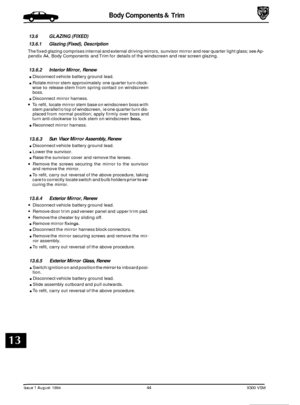
. Pack the annular gaps of the oil seal lips with grease.
. Bearing. Wash the hub assembly thoroughly and 'drift' the affected bearing cup(s) from the hub.
!&!$Q:
rn Hub. At this point the hub may be renewed if required.
Assembly
. Bearing. Assemble the inner bearing track to the hub using service tool 18G 134 and adaptor JD 550 - 5 / 1.
Ensure that the hub inner seal diameter is free of debris or damage and is lightly lubricated prior to assembly.
Only replace complete bearings, never cup or race in isolation.
Assemble the outer bearing cup to the hub using service tool
18G 134 and adaptor JD 550 - 5 / 2. Pack each race with approximately 4 ml of grease and position the inner race onto the stub axle.
Apply a smear of grease to hub inner surfaces and bearing cups. Assemble the hub to the stub axle followed by
outer race, bearing washer and hub nut.
It is not necessary to fill the hub cavity with grease, merely protect from corrosion with a coat of IubricanL'Seat'the bear-
ings by slightly tightening the hub nut whilst rotating the hub. Do not apply load without rotation. m:
. End float. Set a Dial Test Indicator (DTI) as shown in Fig. 1 and adjust the hub nut to achieve the correct end float.
As the adjustment is made, continually load the hub axial-
ly in both directions.
. Without disturbing the end float setting, fit the castellated
nut retainer so that it aligns with both hub nut and stub
axle drilling.
. Secure nut retainer using a new cotter pin.
9 Assembly and fitting is the reversal of this procedure not- ing that; all fixings MUST be tightened to specification
and operation of the braking system verified.
Fig. 1
Issue 1 August 1994 10 X300 VSM
Page 210 of 521

Suspension Systems
. .
SECTION CON TENTS
Subsection Tjf/e
.
SRO
I to IV ........... Preliminary Pages ................................................................... i
11.1 ............. Introduction ........................................................................\
. 1
11.2 ............. Front Suspension. Description ......................................... ..
Page
11.3 ............. Rearsuspension. Description .......................................................... 2
11.4.1
............ Diagnosis & Testing. Tire Wear ......................................................... 3
11.4.2
............ Diagnosis & Testing. Vibration & Roughness .............................................. 3
11.4.3
............ Diagnosis & Testing. Front End Inspection ................................................ 4
11.4.4 ............ Diagnosis & Testing. Upper/Lower Ball Joint Inspection ................................... 4
11.4.5
............ Diagnosis & Testing. Damper Inspection ................................................. 4
11.4.6
............ Diagnosis & Testing. Rear Suspension Inspection .......................................... 5
11.4.7. ........... Diagnosis & Testing. Vehicle Inspection .................................................. 5
11.4 ............. Diagnosis & Testing .................................................................. 3
. 1 1.4.8 ............ Diagnosis & Testing. Diagnostic Procedure Chart ............ ...
. .
........ .....
-
I X300 VSM i Issue 1 August 1994
.
............. 1
............. 6
Page 211 of 521
1. SERVICE TOOLS & EQUIPMENT
Illustration
Not illustrated
Jaguar Number
JDID
JD 60
JDIOO
JD115
JD133
JD135
JD143
JD143-1
50143-2
JD143-3
Description
Hub Remover Rear Suspension
Nishbone Upper Bush Remover
1 Replacer
Remover Steering Arm and Swivel
Hub Ball Pins
Spring Compressor Front Suspension
Camber Tie Down Link (Front)
RemoverIRenewer Front Damper
Lower Bush
Remover
1 Renewer Suspension
Bushes (Main
Tool)
Adaptor Ring Front Sub Frame Rear
Bushes
Anvil adapter
Adaptor Remover
1 Renewer
Suspension Bushes
Issue 1 August 1994 ii X300 VSM
Page 212 of 521
Suspension Systems
Not illustrated
1. SERVICE TOOLS & EQUIPMENT (continued)
JD199
0
Fixing
To be issued
Tightening Torque
(Nm)
JD199-1 Not i II ustrated
Description US98
LM Multi - purpose grease
Molib Alloy
PI907 No1
Molykote 11 1
Lower damper bolt
Wishbone to crossmember fulcrum shaft
Stabilizer mounting bushes
& rear damper top
guide bush
Caliper to carrier bolts
/ guide pins
Description
Notes
Adaptor Remover / Renewer
Suspension Bushes (Bottom Front
Wishbone Inner)
____~ ~ Spring
Compressor Rear Suspension
Damper Retaining Tie Rear
Suspension
Adaptor
Replacer Rear Hub Pivot
Bearing Cup
Driver Handle
Adaptor Remover
Main Shaft Pilot
Bearing Outer Track
Impulse Extractor (slide Hammer)
UNF. Basic Tool
Notes
Issue 1 August 1994 X300 VSM iii
Page 213 of 521
Suspension Systems
Application
Camber angle front suspension
Caster angle (Same setting each side of vehicle)
Wheel alignment
Specification
+0.3' to - 0.8'
3.0' to 6.0'
5'Toe-in f 10'
Note: Geometry is to be checked/set using the mid-laden setting-links. Setting height should correspond to thefol- lowing dimensions:
Front 153 f 5mm under front crossbeam (AJ16) Front 143 f 5mm under front crossbeam (V12) Rear 160 f 5mm under rear edge of 'A' frame
Issue 1 August 1994 iv X300 VSM
Page 214 of 521

Suspension Systems
11.1 INTRODUCTION
This section describes the front and rear suspension systems, and also covers diagnostic procedures.
Fig. 1 Front Suspension Layout
11.2 FRONT SUSPENSION, DESCRIPTION
Theupperrearwishbone(1 Fig.l)andthe upperfrontwishbone(2 Fig.1)arepivotedon the upperfulcrum bolt (3Fig.l), passing through the front cross beam assembly. They are also fitted via an upper ball joint assembly (4 Fig.1) to a verti- cal linkaccommodating the stub axle (5 Fig.l), whereas the vertical linkisfittedvia a lower ball joint assembly (6 Fig.1) to the lower wishbone assembly.
The lower wishbone assembly comprises
a lower rear wishbone (7 Fig.l), lower front wishbone (8 Fig.l), damper (9 Fig.1) (incorporating damper bush 10 Fig.1) and spring pan (1 1 Fig.1) supporting the road spring (12 Fig.1). The lower
wishbone assembly is pivoted on the bushed lower fulcrum shaft (13 Fig.1) which also passes through thecross beam
assembly.
Both independent front suspension assemblies are linked by a stabilizer bar (14 Fig.1) which is secured to the cross
member using a fixing arrangement of mounting rubbers (15 Fig.1, clamps (16 Fig.l), nuts bolts, washers (17 Fig.1) and two link arm assemblies (18 Fig.1). Each link arm assembly is fitted to one end of the stabilizer bar and to one end
of the lower front wishbone using a fixing arrangement of bolts washers and self locking nuts.
All suspension loads, except the damper, are fed into a pressed steel crossbeam which is isolated from the body by
rubber bushes. This mounting method allows the necessary amount of compliance.
The degree
of caster is adjustable via shims positioned on either side of the upper ball joint assembly but camber is facton/ set and is not adjustable. The vertical link and the steering arm form a single forging. Cast iron hubs rotate
on twin tapered roller bearings.
X300 VSM 1 Issue 1 August 1994
Page 215 of 521

Suspension Systems
Fig. 1 Rear Suspension layout
11.3 REAR SUSPENSION, DESCRIPTION
The vehicle's rear suspension layout features a cast wishbone complete with integral lower spring pan (1 Fig.1) sup- porting the independently mounted damper (2 Fig.1) and road spring (3 Fig.1).
Thelowerwishbonearmis boltedtothehubcarrier(4 Fig.1) by meansofa pivot bolt (5Fig.l),allowingfortoe-in adjust- ment. When the pivot bolt is seated correctly in the plate located on the wishbone arm, it has a small clearance at the
sides but full clearance at the top and bottom.
Rotation of the bolt head, with eccentric constrained between the vertical faces, causes the bolt shank to be moved in
the horizontal plane, thus displacing the hub carrier and effecting wheel alignment adjustment.
The snubber
(6 Fig.1) positioned above the hub carrier, prevents this from touching the vehicle body.
The hub
carrier/wishbone assembly, is pivoted on the wishbone fulcrum bolt (7 Fig.1) and is then secured by a nut and
washerfixing arrangementtothe pendulum assembly (8 Fig.1) andthe wishbonetie assembly (9 Fig.l).The differential
strut (10 Fia.1) is fastened to the wishbone tie assemblv and to a bracket, welded to the vehicle bodv. Both, the pendu- lum and the wishbone tie assembly are fitted to the differential unit which is mounted on to a mounting frame and a rear frame carrier.
The supercharged vehicle (manual only), the XJ12 and the sport versions are equipped with
a rear stabilizer bar, a dif- ferential monostrut instead of two single struts, a modified wishbone tie and two stabilizer bar drop links which are
seated on the lower wishbone cast bosses.
0
0
e
Issue 1 August 1994 X300 VSM
Page 216 of 521

may include:
0
0
Loose or worn wheel bearings.
Loose or worn suspensions or steering components.
0 Worn or damaged drive shaft slip yoke joint.
0 Front disc rotor runout.
o Loose engine or transmission supports.
0 Driveline alignment.
0 Engine driven accessories.
Suspension Systems
11.4 DIAGNOSIS AND TESTING
' 11.4.1 Tire Wear
Tires should be inspected as abnormal or excessive wear may becaused by incorrect wheel alignment, wheelbire im- balance, or incorrect tire pressure.
1 1.4.2 vibration and Roughness
Vibration, roughness, and shimmy conditions may be caused by excessive tire or wheel runout, worn or cupped tires,
or wheel and tire unbalance.
Most of these conditions are due to irregularities in the road surface, hence driving the vehicle on different types of
road surface will often indicate the cause of the condition.
Do not automatically suspect the tires when attempting to diagnose a vibration concern as other sources of vibration
Before investigating any other vibration concerns,
a roaG &est and a customer inter\,.dw (if possible) should be carried
out. This can provide much of the information needed to find the source of vibration.
Drive the vehicle on a road that is preferably smooth and free of undulation and
if vibration is apparent note, the speed at which thevibration occurs, whattype of vibration occurs in each speed range (mechanical or audible), howthevibra- tion is affected by changes in vehicle speed , engine speed and engine torque, and the type of vibration sensitivity
(torque sensitive, vehicle speed sensitive, or speed sensitive).
Some of the condition terms used when describing sources of vibration are explained as follows:
0 Torque Sensitive
This condition can be improved or worsened by accelerating, decelerating, coasting, maintaining
a steady
vehicle speed and application of engine torque.
0 Vehicle Speed Sensitive
This means that the vibration always occurs at the same vehicle speed and is not affected by engine torque,
engine rpm, or transmission gear selection.
B
0 Engine Speed Sensitive
This means that the vibration occurs
at varying vehicle speeds when a different transmission gear is selected.
It can sometimes be isolated by increasing or decreasing engine speed with the transmission in 'NEUTRAL', or
by stall testing with the engine in gear. If the condition is enginesensitive, the condition is not related to tires.
If the road tests indicates that the vibration is related to the tires or wheels,use a 'lire Wear Diagnosis Chart' to
investigate the cause of concern. Should the road test indicate that there is tire whine, but noshake or vibration,
the noise originates from the contact between the tire and the road surface.
X300 VSM 3 Issue 1 August 1994