Page 305 of 521

Body Components & Trim .Birpa,
13.8.8 Seat Belts, Description
Three types of seat belt are used: tear loop inertia seat belts used on front seats in association with driver and passenger
airbags, standard inertia types fitted to the outer, rear seats and static belts fitted to the
center, rear seat.
Front passenger seat belts are fitted
with tear loop buckles while drivers seat belts have the tear loop fitted to the out- board anchorage. The front seat belts are provided with height adjuster units which are attached one to each of the
'B' posts.
13.8.9
Where emergency locking retractorlautomatic locking retractor seat belts are provided, the belts have two operating
modes:
1.
2.
The inertia reel mode operates to allowthe occupant some freedom of torso movement. The static reel mode prevents
belt payout and thereby does not allow the occupant freedom of torso movement. When the seat belt is attached to
a child seat which has its own independent harness, the static mode must be used.
The seat belt defaults to the inertia reel (adult passenger) mode when
in the stowed (fully retracted) position.
To activate the static reel (child seat) mode, pay out the belt to its
full extension. The ratchet mechanism is now en- gaged. When retracting the belt back into the reel, the ratchet operation may be felt. It can be noticed that the belt is
unable to reverse direction.
To revert to the inertia reel mode, pay the belt back into the reel to the stowed position.
Emergency Locking Retractor / Automatic locking Retractor Seat Belts
Inertia reel mode, emergency locking retractor, for adult passengers
Static reel mode, automatic locking retractor, for children
(in child seats).
1. Height adj. to post 7. Static 1 inertia buckle bracket I body 2. Height adj. to belt anchor 8. Tear loop buckle bracket 3. Inertia belt anchor 9. Belt buckle bracket 4. Inertia bracket / body 10. Reel bracket 1 body
5. 11. Belt anchor I body
6. 12. Upper guide I body
Inertia
reel bracket I body
Inertia 1 static buckle bracket I body
Fig.
1 Seat Belt Location and Anchorages
0
0
Issue 1 August 1994 50 X300 VSM
Page 306 of 521

Body Components & Trim
13.8.10 Tear loop Seat Belts, Description
The tear loop seat belt (Fig.1) is used to control the rate of forward travel of the occupant towards the deployed airbag
(the airbag is covered in Section 15, Electrical). The tear loop assembly is designed to release additional webbing when
the stitching, which retains the webbing loops, breaks under
a predetermined load. The wires (1 Fig. 1) within the as- sembly have the following functions:
0 To protect the stitching from 'normal' loads such as heavy braking or cornering.
o To control the rate of deployment.
0 To support the extended head following deployment.
When the passenger unit has been activated, the buckle will extend from the shroud and reveal
a warning label (2 Fig. 1); the extent of deployment will depend upon the severity of the load.
-: IF THE LABEL IS VISIBLE AT ALL (3 FIG. 3). THE COMPLETE ASSEMBLY MUST BE RENEWED, AS MUST
ANY SEAT BELT WHICH HAS BEEN WORN IN AN ACCIDENT.
2
Fia. 1 Tear LOOO Seat Belt
X300 VSM 51 Issue 1 August 1994 ~~
Page 307 of 521

Body Components & Trim
0 13.8.1 1 Front Seat Belt Buckle Unit, Renew
. Disconnect vehicle battery ground lead.
. Remove the front seat cushion.
. Disconnect cable connector and remove cable into seat
frame.
. Remove securing bolt, buckle unit and wavy washer.
. To refit, carry out reversal of the above procedure.
13.8.12 Front Seat Belt, Renew
. Position the front seat for access.
. Disconnect vehicle battery ground lead.
. Release 'B' post upper trim and belt aperture cover.
. Remove cover from seat belt upper fixing.
. Removeseat belt upper fixing and releaseseat belt anchor
. Lower the upper trim pad with seat belt onto the seat.
Remove 'B' post lower trim.
. Remove seat belt lower fixing, disconnect anchor plate
and remove wavy washer.
. Release upper trim pad from seat belt. Remove upper
guide fixings at 'B' post.
. Remove seat belt reel fixings and remove reel and belt as- sem bly.
. Refit seat cushion.
Secure seat belt reel to the specified torque.
Fit and secure upper guide plate to 'B' post.
Pass the seat belt through the upper trim pad.
. Fit wavy washerto lower anchor,fit lower anchor plate and
. Refit lower 'B' post trim panel.
. Refit upper 'B' post trim panel.
from
height adjuster; remove wavy washer.
0
nut; tighten to specified torque.
Place wavy washer
on height adjuster stud, fit belt upper
anchor and nut; tighten to specified torque.
. Fit plastic cover and split finisher.
13.8.13 Rear Inertia Seat Belt, Renew
= Remove seat cushion, rear seat squab and rear parcel tray.
. Remove foam pad from rear shelf and remove seat belt
. Remove buckle assembly, washers and spacers.
. Remove side seat belt buckle and the lower anchorage
. Move the belt aside and remove the upper spacer.
Remove theseat belt bracket/ body fixing and remove reel
= Remove seat belt reel / securing bracket fixings.
. Remove the reel and belt assembly.
. To refit, carry out reversal of the above procedure.
0 buckle bolt.
belt.
/ bracket assembly.
m
Issue 1 August 1994 52 X300 VSM ~~
Page 308 of 521
Body Components & Trim -
0 13.8.14 Rear, Center, Static Seat Belt, Renew
Remove rear seat cushion.
Remove seat belt buckle bolt and remove buckle.
Remove washers, spacers and side seat belt buckle.
Remove
center lap strap buckle and seat belt strap secur- ing bolt.
Remove the strap and buckle assembly.
Remove washers, spacers and side seat belt buckle.
To refit, carry out reversal of the above procedure.
X300 VSM 53 Issue 1 August 1994
Page 309 of 521
Page 310 of 521

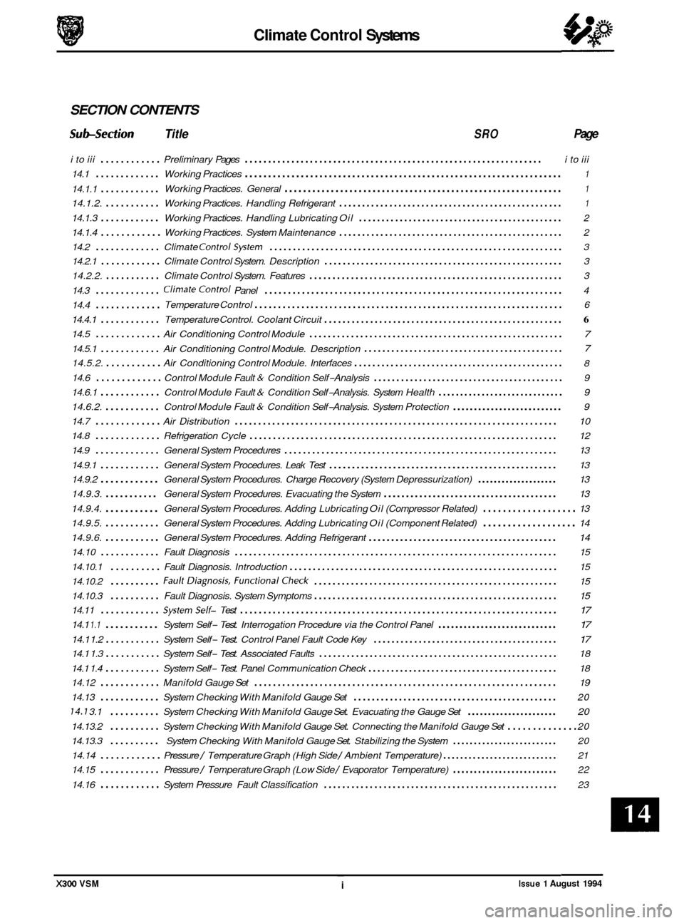
Climate Control Systems
SECTION CONTENTS
Subsection Title SRO Page
i to iii ............ Preliminary Pages ................................................................ i to iii
14.1
............. Working Practices .................................................................... 1
Working Practices. General ............................................................ 1 14.1.1 ............
14.1.2. ........... Working Practices. Handling Refrigerant ................................................. 1
14.1.3 ............ Working Practices. Handling Lubricating Oil ............................................. 2
14.1.4
............ Working Practices. System Maintenance ................................................. 2
14.2
............. Climate ControlSystem ............................................................... 3
14.2.1
............ Climate Control System. Description .................................................... 3
14.2.2.
........... Climate Control System. Features ....................................................... 3
14.3
............. ClimateControl Panel ................................................................ 4
14.4
.............
14.4.1 ............ Temperature Control. Coolant Circuit .................................................... 6
14.5 ............. Air Conditioning Control Module ....................................................... 7
14.5.1 ............ Air Conditioning Control Module. Description 7
14.5.2. ........... Air Conditioning Control Module. Interfaces .............................................. 8
14.6
............. Control Module Fault & Condition Self-Analysis .......................................... 9
14.6.1
............ Control Module Fault & Condition Self-Analysis. System Health ............................. 9
14.6.2.
........... Control Module Fault & Condition Self-Analysis. System Protection .......................... 9
14.7
............. Air Distribution ..................................................................... 10
14.8
............. Refrigeration Cycle .................................................................. 12
14.9
............. General System Procedures ........................................................... 13
14.9.1
............ General System Procedures. Leak Test .................................................. 13
14.9.2
............ General System Procedures. Charge Recovery (System Depressurization) .................... 13
14.9.3.
........... General System Procedures. Evacuating the System ....................................... 13
14.9.4.
........... General System Procedures. Adding Lubricating Oil (Compressor Related) ................... 13
14.9.5.
........... General System Procedures. Adding Lubricating Oil (Component Related) ................... 14
14.9.6.
........... General System Procedures. Adding Refrigerant .......................................... 14
14.10
............ Fault Diagnosis ..................................................................... 15
14.10.1
.......... Fault Diagnosis. Introduction .......................................................... 15
14.10.2
.......... FaultDiagnosis. FunctionalCheck ..................................................... 15
14.10.3
14.11
............ Systemself- Test .................................................................... 17
14.1 1.1 ........... System Self- Test. Interrogation Procedure via the Control Panel ............................ 17
14.1 1.2 ........... System Self- Test. Control Panel Fault Code Key ......................................... 17
14.1 1.4 ........... System Self- Test. Panel Communication Check .......................................... 18
14.13
............ System Checking With Manifold Gauge Set ............................................. 20
14.7 3.1 .......... System Checking With Manifold Gauge Set. Evacuating the Gauge Set ...................... 20
14.13.2 .......... System Checking With Manifold Gauge Set. Connecting the Manifold Gauge Set .............. 20
14.13.3
.......... System Checking With Manifold Gauge Set. Stabilizing the System ......................... 20
14.14
............ Pressure / Temperature Graph (High Side / Ambient Temperature) ........................... 21
14.15
............ Pressure / Temperature Graph (Low Side / Evaporator Temperature) ......................... 22
14.16
............ System Pressure Fault Classification ................................................... 23
Temperature
Control
.................................................................. 6
............................................ a
.......... Fault Diagnosis. System Symptoms ..................................................... 15 a
14.1 1.3 ........... System Self- Test. Associated Faults .................................................... 18
14.12
............ Manifold Gauge Set ................................................................. 19
X300 VSM ~ i Issue 1 August 1994
Page 311 of 521
Climate Control Systems
Illustration 1 JaguarNumber I Deription Not-
not i II ustrated
11. TORQUE TIGHTEN1 NG SPEC1 FICATIONS
Recovery 1 Recycling 1 Recharging
station See
standards
fixing
Blower assembly to body
Condenser to receiver
1 drier (tube nut)
lightening Torque
I (Nm)
4-7
14
- 18
Hoses to evaporator plate
Liquid line to receiver
1 drier (tube nut)
I Discharge hose to condenser (tube nut) I 22 - 28 I
7 - 10
14- 18
I Heater 1 cooler case to body I 5-7 I
I Hoses to compressor I 7-10 I
I Mountina strut to heater / cooler case I 5-7 I
X300 VSM Issue 1 August 1994 ii
Page 312 of 521

Climate Control Systems
Description U-
HFC 134A - ICI Klea or
equivalent
Polyalkyleneglycol (PAG) Compressor lubricant
Refrigerant
111.
Notes
Recyclable. NOT
compatible
with CFC 12
Absorbs water readily. NOT
compatible with mineral based
oils
SERVICE MATERIALS
Standard for Recovery I Recycle 1 Recharge Equipment.
Recovery rate
Cleaning capability
Oil separator
.Moisture indicator
Vacuum pump
Filter Replaceable with moisture indicator
Charge Hoses
Feature Requirement
0,014 - 0,062 m3 / min. (1,36 kg in 20 minutes)
15 parts per million (ppm) moisture; 4000 ppm oil; 330 ppm non condensable gases
in air
With hermetic compressor and automatic oil return
Sight glass type, sensitive to 15 ppm minimum
2 stage 0,07 - 0,127 m3 I min.
Selectable charge weight and automatic delivery
Dedicated HFC 134A port connections.
Iv. SERVICE DATA
Application
Charae weight
Lubricant capacity
Compressor pressure relief valve
Drive belt 12 cylinder
Drive belt tension
All figures apply to a cold belt
Special note
Drive belt tension measuring point
Drive belt 6 cyclinder
Drive belt tension
All figures apply to a cold belt
Drive belt tension measuring point
Specification
160 - 200 ml
Opening point 34 Bar. Closing point 27,6 Bar.
Maximum leakage rate of 113 liters 1 minute @ 41 Bar
7 rib Poly
-vee; 1450 mm long
Burroughs method
- New belt 790 N; If tension falls
below 270 N reset at 630 N
Clavis method
- New belt 114 to 120 Hz; If tension falls
below 70 Hz reset at 87 to 93 Hz
For new belt; rotate engine 3 revolutions minimum and
retension
Mid-way between crankshaft and compressor pulley ~
4
rib Poly-vee X 1010 mm long
Burroughs method
- New belt 556 to 578 N; If tension
falls below 245 N reset at 378 to 400
N
Clavis method - New belt 167 to 173 Hz; If tension falls
below 85 Hz reset at 127 to 133 Hz
Mid
-way between crankshaft and compressor pulley on
the upper run
1 Charge pressure I Heating element to increase pressure
Issue 1 August 1994 X300 VSM iii