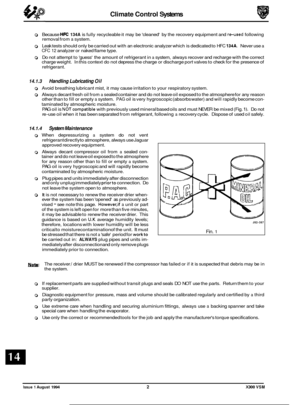
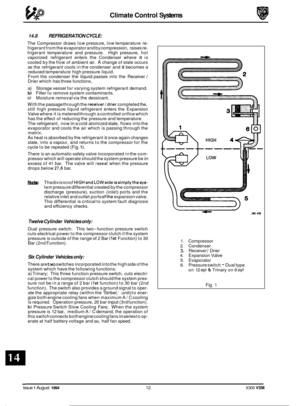
Page 337 of 521
Page 338 of 521

Electrical cl
.
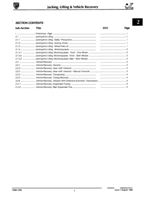
SECTION CONTENTS
Subsection Title SRO Page
i ................ PreliminaryPages .................................................................... i
15.1 ............. Supplemental Restraint System (SRS) .................................................... 1
15.1.1 ............ SRS. General Description .............................................................. 1
15.1.2 ............ SRS. Handling Undeployed Modules .................................................... 2
15.1.3 ............ SRS. Emergency First Aid Procedures .................................................... 3
15.1.4
............ SRS. Safety Procedures. Handling Deployed Modules ...................................... 3
15.1.5 ............ SRS. Safety Procedures. Handling Undeployed Damaged Modules ........................... 3
15.1.6. ........... SRS. Fire Hazard Information .......................................................... 4
15.1.7.
........... SRS. Ventilation ...................................................................... 4
15.1.8 ............ SRS. RespiratoryPrecautions ........................................................... 4
15.1.9.
........... SRS. Eye Protection ................................................................... 4
15.1.10
.......... SRS. Protective Clothing ............................................................... 4
15.1.11 ........... SRS. Handling & Storage Precautions .................................................... 4
15.1.12 .......... SRS. Modules. Assembly/ Removal/Setvice Instructions ................................... 4
15.1.13 .......... SRS. Spillage & Leakage ............................................................... 5
15.1.14 .......... SRS. Scrapping Vehicles With Live Airbags ............................................... 5
15.1.15 .......... SRS. Scrapping Vehicles With Deployed Airbags .......................................... 6
15.1.16 .......... SRS. Disposal of Live Airbag Modules ................................................... 6
15.1.17 .......... SRS. Disposal of Deployed Airbag Modules .............................................. 7
15.2 ............. Instruments ........................................................................\
. 8
15.2.1
............ Instruments. General Description ....................................................... 8
15.2.2 ............ Instruments. Analog Display ........................................................... 8
15.2.3
............ Instruments. Indicator Lamps ........................................................... 8
15.2.4.
........... Instruments. Liquid Crystal Display ..................................................... 8
15.2.5.
........... Instruments. Transducers .............................................................. 8
15.2.6. ........... Instruments. Panel. General ........................................................... 8
15.2.7.
........... Instruments. Gauges .................................................................. 9
15.2.8. ........... Instruments. Odometer ............................................................... 10
15.2.9
............ Instruments. Trip Computer ........................................................... 10
15.2.10 .......... Instruments. Driver Information Messages ............................................... 10
15.2.11 ........... Instruments. Illumination ............................................................. 10
15.2.12 .......... Instruments. General Repair Notes ..................................................... 10
15.3 ............. Speed Control ...................................................................... 11
15.4 ............. Driver Ergonomics .................................................................. 12
15.5
............. Battery& ChargingSystem ........................................................... 13
15.5.1 ............ Battery, General .................................................................... 13
15.5.2 ............ Battery, ReserveCapaci ty ............................................................. 13
15.5.3.
........... Battery. Cranking Performance ........................................................ 13
15.5.4 ............ Battery. Electrical Data ............................................................... 13
15.5.5
............ Battery. State of Charge .............................................................. 13
15.5.6 ............ Battery, Rate of Charge ............................................................... 13
15.5.7 ............ Battery. LoadTest ................................................................... 13
15.5.8 ............ Battey. Specific Gravity Test .......................................................... 14
15.5.9 ............ Battery. Electrolyte Temperature Correction .............................................. 14
15.5.10 .......... Battery. Health & Safety Precautions ................................................... 14
15.5.11. .......... Battery. Remove & Refit ......................................... 86.15.01 ............ 15
e
e
X300 VSM i Issue 1 August 1994
Page 339 of 521

rl Electrical
SECTION CONTENTS
Sub-section Title SRO Page
15.6 .............
15.6.1 ............
15.6.2 ............
15.6.2.1 ..........
15.6.2.2 ..........
15.6.2.3 ..........
15.7 .............
15.8 .............
15.9 .............
15.9.1 ............
15.9.2 ............
15.10 ............
15.10.1 ..........
15.10.2 ..........
15.10.3 ..........
15.10.4 ..........
15.11 ............
15.11.1 ...........
15.12 ............
15.12.1 ..........
15.12.2 ..........
15.12.3 ..........
15.13 ............
15.13.1 ..........
Power Wash & Screen Wash / Wipe .................................................... 16
Windscreen Wipers and Washers. General Description .................................... 16
Windscreen Wipers and Washers. Switch ............................................... 16
Windscreen Wipers and Washers. Single Wipe Operation ................................. 16
Windscreen Wipers and Washers. Programmed Wash / Wipe Operation ..................... 77
Windscreen Wipers and Washers. Headlamp Power Wash Operation ....................... 17
Closures Switching .................................................................. 18
In-Car Entertainment ................................................................ 19
Lamps & Lighting Logic .............................................................. 20
Lamps & Lighting Logic. Exterior Lighting. General Description ............................ 20
Lamps & Lighting Logic. Interior Lighting. General Description ............................ 21
Harnesses &Cables ................................................................. 22
Harnesses
& Cables. Battery Power Distribution Cables. General ........................... 22
Harnesses & Cables. Main Harnesses. General Description ................................ 24
Harnesses & Cables. Link Harnesses. General Description ................................. 26
Harnesses & Cables. Harness Connectors. General Description ............................. 28
Motors and Solenoids ................................................................ 30
Motors and Solenoids. General Description ............................................. 30
Relays ........................................................................\
..... 32
Relays. Engine Compartment. General Description ....................................... 32
Relays. Passenger Compartment. General Description .................................... 34
Relays. Trunk. General Description .................................................... 36
Control Modules .................................................................... 38
Control Modules. General Description ................................................. 38
Page 340 of 521

SERVKE TOOLS & EQU1PMENT
Illustration I JagusrNumbw I Description I NOtOS
Instrument pack to support panel
to
be issued
11. TORQUE TlGHTENlNG SPEC1FKATIONS
1.8
Fixing
Fascia to console
Fascia to support bracket
(Nm)
I TigM.ningToqrn
I
2.5-3.5
22-28
Instrument pack to fascia
Strut to fascia 2.5-3.5
1.5-2.5
I I 22-28 1 Tunnel bracket to bodv
I Bolster to tunnel bracket I 1.5 I
Fascia support strut to BIW 7-1 0
CPU brackets to fascia 5-7
Fascia demister bracket to fascia 1.5
Fascia and air conditioning location to body 1
Air distribution box duct to air distribution box
Airbag carrier mounting bracket to fascia 1
5-7
instrument pack support bracket to fascia
Airbag bracket to fascia 5-7
1.5-2.5
Air distribution box to fascia
Airbag upper bracket to carrier 1.5-2.5
1.5-2.5
Instrument pack support bracket and strut
Fascia assembly to BIW 5-7
22-28
111. SERVKE MTERlALS
0, Description
Airbag door brackets to fascia
Airbag door bracket to door frame assembly 5-7
5-7
US08 Notes I I
1 to be issued I I
X300 VSM iii Issue 1 August 1994
Page 341 of 521
Page 342 of 521
Page 343 of 521

15.1.2 Handling Undeployed Modules
The electrically-activated airbag module contains sodium azide and sodium nitrate which are poisonous and
extremely flammable substances.
Their contact with acid, water or heavy metals may produce harmful and irritating gases or combustible compounds.
The airbag module is
non-serviceable and must not be dismantled, punctured, incinerated or welded.
WARNING: DO NOT ATTEMPT ANY REPAIRS TO THE AIRBAG MODULE.
Never measure the resistance of the airbag module, as this may cause the airbag to deploy. Suspect modules must be returned to Jaguar Cars Ltd. or their importer for replacement.
Tampering or mishandling can result in personal injury.
Keep away from heat, sparks and open flames. Do not store
at temperatures exceeding 93O Celsius (200OF).
Keep away from electrical equipment as electrical contact may cause ignition.
Do not drop or impact airbag module.
Always position module 'cover
-up'.
Ensure that the connector is protected to prevent damage.
J76-1058
Fig. 1 The Driver-side Airbag
Store modules in a secure lockable cabinet.
Never position projectile material over the undeployed airbag as this can cause injury in the event of inadvertent
deployment.
Page 344 of 521

Do not wrap arms around module when carrying and always carry module with cover and ventsfacing awayfrom body
to avoid personal injury in the event of inadvertent deployment.
Never carry airbag module by wires or the connector.
The chemical propellant mixture deploying the airbag is
a solid and therefore inhalation exposure is unlikely even if module is ruptured without deployment.
As far as practicable, avoid skin contact with, or ingestion of, the materials present after combustion. Exposure to high
concentrations of propellant mixture may cause headache, nausea, blurred vision, faintness, cyanosis, lowering of
blood pressure, tachycardia and shortness of breath.
WARNING:SODlUM AZlDE HAS BEEN LISTED AS AN 'EXTRAORDINARY HAZARDOUS SUBSTANCE OR
CARCINOGEN BY THE STATE OF MASSACHUSETTS, USA. SODIUM AZlDE HAS BEEN LISTED ON THE 'RIGHT TO KNOW HAZARDOUS SUBSTANCE LIST' BY THE STATE OF NEW JERSEY AND IS ALSO
REGARDED AS A 'SPECIAL HEALTH HAZARD SUBSTANCE BY THE STATE. THE PROPELLANT MIXTURE IS SENSITIVE TO PREMATURE IGNITION BY ELECTRICAL SOURCES IF NOT PROPERLY PROTECTED AND
ISOLATED.
15.1.3 Emergency First Aid Procedures
If the airbag is ruptured without deployment and exposure to the propellant mixture occurs, observe the following
first-aid treatments:
0 Ingestion - Do not induce vomiting and seek prompt medical attention.
0 Skin contact- Immediately wash skin with soap and water and seek medical attention.
0 Eyes - Immediately flush eyes with water for at least 20 minutes and seek prompt medical attention.
0 Inhalation - Immediately move victim to fresh air and seek medical attention.
0 Physical trauma, eg burns, abrasions, or impact due to premature ignition or deployment of the inflator
assembly - Treat symptomatically and seek prompt medical attention.
0
15.1.4
See 'Emergency First Aid Procedures' above.
Prevent contact of the inflator with liquids, combustibles and flammable materials. Failure to followthese instructions
could result in chemical burns and personal injury.
Ensure modules are cool before handling.
After deployment the airbag surface contains small deposits of sodium hydroxide which can cause irritation to the skin
and eyes.
When handling deployed airbags, always wear rubber gloves to
BS 1651 grade 2 or equivalent, and chemical resistant
goggles to BS 2092 grade 2 or equivalent.
After handling deployed airbags, immediately wash hands and exposed skin surface areas with mild soap and water.
Sakty Procedures For Handling Depbyed (Fid) Modules
15.1.5 Safety Procedures For Handling Undeployed Damaged Modules
The material inside the module is hermetically sealed and is completely consumed during deployment.
No attempt should be made to open the module
as this leads to a risk of exposure to sodium azide.
In the unlikely event of
a gas generator being damaged, it must be examined by trained personnel before any attempt
is made to remove and/or deploy.
Full protective clothing must be worn when dealing with any spillage.
Ruptured units must be stored away from acids, halogens, heavy metals and metal salts. Damaged units may produce
hydrazoic acid if exposed to liquids.
Failure to comply with these instructions may result in fire, noxious fumes and severe personal injury or death.
X300 VSM 3 Issue 1 August 1994