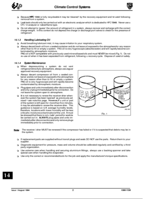
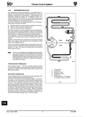
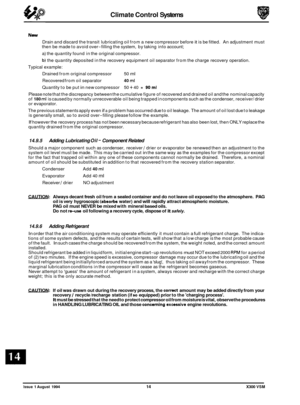
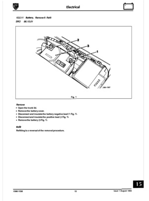
Page 225 of 521

The input frequency from each wheel speed sensor signal is translated by the ABS I TC CM, into a comparable wheel
speed. The ABS / TC CM continually monitors the system. False wheel speed information, such as sudden speed
changes in excess of 20 km / h or excessive speeds, are detected as a 'sensor malfunction'. The ABS / TC CM reacts
to fault conditions in the following ways:
Inhibit- ABS/traction control is inhibited until the sensed speed returns to within an acceptable limit, whereupon ABS
/traction control is restored. Conventional braking is unaffected. Depending on vehicle speed the ABS/traction control
warning lights may come on.
DisaMe - ABS /traction control is Disabled (switched off) and the ABS /traction control warning lights come on. The
system will not be restored until the engine is switched off and restarted orthe fault has been rectified. Afterthe system
has been disabled, the warning lamps remain on until the vehicle has reached a speed of 20 km/ h during thefirst igni- tion cycle after fault rectification.
Full diagnostic information for the ABS /TC
CM is given in the Electrical Diagnostic Manual (EDM), Section 12.
Issue 1 August 1994 2 X300 VSM
Page 226 of 521

Brakes (a)
12.1.2. Anti-lock Braking / Traction Control Operation
The rear wheels are controlled collectively on a 'select-low' principle during ABS operation. During traction control,
separate circuits allow individual control of the rear wheels. To facilitate this the valve block has four outlet ports.
The
ABS/TC CM is integrated with the valve block. The pump, motor, valve block and control module are supplied as
a unit and are non-sewiceable. Faulty units must be renewed as a whole.
Both front and rear brakes on
all vehicles are fitted with single piston caliper assemblies. Ventilated brake rotors, with
provision for parking brake shoes at the rear, are fitted all round.
0
Issue 1 August 1994 X300 VSM 3
1. Vacuum booster 9. Pressure conscious reduction valve 2. Vacuum hose 10. Ventilated brake rotor 3. Tandem master cylinder 11. Single piston caliper 4. Primary brake circuit 12. %way brake pipe connector
5. Secondary brake circuit 13. Wheel speed sensor
6. Hydraulic pump / motor unit 14. ABS warning lamp 7. Valve block 15. Brake fluid level warning lamp
8. ABS/TCCM
Fig. 1 ABS / Traction Control System
The vacuum booster (see Fig.
1) is mounted on the brake pedal box and secured by three bolts. Brake pedal force is
increased by the vacuum booster which activates the Tandem Master Cylinder (TMC) intermediate piston. Brake fluid
is supplied to the pump inlet ports on two separate circuits. The primary circuit supplies the front brakes whilst the
secondary circuit supplies the rear brakes.
Page 227 of 521

Pressure conscious reduction valves (PCRVs) are fitted between the outlet of the valve block and the rear brake circuit
to optimize. The valves are fitted to prevent over braking due to the increased size of the rear brake calipers which are
required for traction control. Up to a threshold of 15 bar, brake pressure to the front and rear brakes is equal. Above
15 bar the PCRVs reduce pressure to the rear brakes to provide a closer balance between front and rear brakes and
optimize road adhesion.
Wheel speed sensors are fitted to all wheels to transmit wheel speed information to the control module. The module
uses this information to modulate brake pressure during anti
-lock braking or traction control.
12.1.3. Anti-lock Braking Operation
170 287
1. Vacuum booster 9. Pressure conscious reduction valve
2. Vacuum hose 10. Ventilated brake rotor
3. Tandem master cylinder 11. Single piston caliper
4. Primary brake circuit 12.
%way brake pipe connector
5. Secondary brake circuit 13. Wheel speed sensor
6. Hydraulic pump I motor unit 14. ABS warning lamp 7. Valve block 15. Brake fluid level warning lamp
8. ABSICM
Fig. 1 Brake System (non-Traction Control)
The rear brakes (see Fig. 1) are controlled collectively on a
'select-low' principle. Under ABS braking conditions, equal
brake pressure is applied to both rear calipers, although only one wheel may have a tendency to lock.
The valve block has three outlet
ports, Brake fluid volume is supplied equally to the rear brakes via the %way brake
pipe connector.
Issue 1 August 1994 4 X300 VSM
Page 228 of 521
Page 229 of 521

12.1.5. ABS Components
Hydraulic Module
The hydraulic module is located under the bonnet adjacent
to the engine compartment firewall. It is secured within a steel mounting bracket at three securing points. All elec- tronic and power connections are made through one cable
loom connect ion.
The hydraulic pump
(1 Fig. 1) is a reciprocating two-circuit pump in which one brake circuit is assigned to each pump
circuit. The pump supplies adequate pressure and volume
supply to the brake circuits under anti
-lock braking condi- tions. The pump is driven by and electric motor (2 Fig. 1). The
pump housing incorporates two low pressure accumulators
and damping chambers for each brake circuit.
A modulator valve block
(3 Fig. 1) incorporates the ABS CM or ABS / TC CM (4 Fig. 1). Vehicles with traction control are
fitted with a throttle position actuator (5 Fig. I), which is an
electrical device controlled by the ABS 1 TC CM.
Valve blocks on vehicles without traction control comprise
six solenoid valves, three normally open (NO) inlet valves
and three normally closed
(NC) outlet valves. These valve
blocks have three outlet ports. Valve blocks on vehicles with
traction control comprise nine solenoid valves, four
NO inlet valves,four NC outlet valves and one special isolating valve.
Fig. 2 shows a hydraulic module for vehicles with traction
control. The valve block (2 Fig. 2) has four outlet ports (Indi- vidual control of the driven wheels).
A BS CM, A BS / TC CM
The ABS CM or ABS TCI CM locates beneath the modulator
valve block and is secured by
two screws. The CM houses
the solenoids which operate the inlet and outletvalves of the
modulator valve block. When fitted, the valve stems locate
in the
CM mounted solenoids. There is no electrical connec- tion between the CM and the modulator valve block. Fig. 3 shows an ABS TC 1 CM having nine solenoids.
The
CM functions include the following:
0 Providing control signals for the operation of ABS
and traction control solenoid valves
0 Calculating wheel speed from voltage signals trans- mitted by the wheel speed sensors
0 Monitoring of all electrical components
0 On Board Diagnostics (OBD): storage of possible fail- ures in a non-volatile memory.
The signals from the four wheel speed sensors are indepen
- dently processed by the ABS CM or ABSITC CM, calculating
numerical values which correspond directly to the wheel
speed. These values are converted into control signals for
pressure modulation during ABS control.
The ABS and traction control
are continuously monitored,
whilst the ignition is on,for possiblefaults and interruptions.
If a fault is detected, the module deactivates the ABS and
indicates this by lighting the ABS warning lamp. In a fault
condition, conventional braking is unaffected. The module
stores fault codes in a non
-volatile memory which can be
read via the OBD link.
U: For electrical diagnostic information on the ABS I traction control systems, refer to EDM, Section 12. Fia.
1
Fia. 2
Fin. 3 I
J70286
Issue 1 August 1994 X300 VSM
Page 230 of 521
0 12.1.6 Calipers
Both front and rear brakes on all vehicles are fitted with
single piston caliper assemblies that act upon 28mm thick
ventilated brake rotors (front brakes) and 20mm thickventi- lated brake rotors/hubs (rear brakes). Rear ventilated brake rotordhubs are fitted to cope with the increased demands- brought about by traction control.
The brake rotors must be renewed
whenthe minimumthick- ness specified below is reached:
0 Front brake rotor - 27mm
0 Rear brake rotor - 18.5mm.
On the front brakes (Fig. 1) two bolts secure the caliper
carrier to the suspension vertical link.
On the rear brakes (Fig. 2) two bolts (wire locked) secure the
caliper carrier to the hub carrier.
Fig. 1
\
Fig. 2
J70-278
X300 VSM 7 Issue 1 August 1994
Page 231 of 521

The caliper (1 Fig. 1) is mounted on the carrier (2 Fig.1) by
means of two guiding pins (3 Fig. 1) and a caliper retaining
clip (5 Fig. ILTheguiding pins(3Fig. 1)slidein bushes(4 Fig. 1) fitted to the caliper.
The guiding pins are fitted with dust caps which must be
fitted when reassembling the caliper.
Inspection and Cleaning
WAR- BRAKE LINING DUST CAN, IF INHALED, DAM-
AGE YOUR HEALTH. ALWAYS USE A VACUUM
BRUSH TO REMOVE DRY BRAKE LINING DUST.
NEVER USE AN AIR LINE.
When fitting new brake pads always take necessary precau- tions and remove the brake dust from around the caliper
area. After renewal, pump the brake pedal several times to
centralize the new brake pads.
W: If both front and rear calipers have been removed
from the vehicle, take care not to mix up left and
right hand caliper bodies. I Fig. 1
Remove
all brake dust from the caliper, carrier and brake rotor. Thoroughly clean the pad abutment areas, avoid dam- aging the piston and dust cover.
CAUTION: When cleaning brake components only use a proprietary fluid. Never use petrol. Use of petrol, paraffin
or other mineral based fluids can prove dangerous.
Examine all the components for signs of wear, damage and corrosion. Pay particular attention to the piston and piston
bore.
Remove caliper body corrosion with a wire brush or wire wool.
No attempt should be made to clean a badly corroded
or scored piston bore. The caliper must be renewed
CAUTIW: No attempt should be made to clean corroded bolts.
Inspect the caliper guide pins, ensure that they are not corroded or seized and that the caliper moves freely. If they are
difficult to remove or corroded in any way, they must be replaced together with new dust covers.
CAUTION: Ensure that working surfaces and hands are clean. Use only brake fluid of the correct specification to lubri- cate the new seals when fitting.
When reassembling always renew piston seals. Lubricate the new piston seal and fit carefully to the inner groove of the piston bore.
Issue 1 August 1994 a X300 VSM
Page 232 of 521

Brakes (e#
12.1.7. Parking Brake
J70 293
W
1. Parking brake lever 2. Front cable 3. Relay lever 4. Driveshaft securing bracket 5. Intermediate cable 6. Cable equalizer
7. In-line cable connector 8. Rear cable RH 9. Rear cable LH
10. Parking brake switch and harness 11. Parking brake warning lamp
Fig.
1 Parking Brake Layout
All vehicles are fitted with identical parking brake systems.
When the parking brake lever
is operated, the cable system applies equal force to both RH and LH brakeshoe expander
assemblies. The brake shoes expand and press against the hub assembly, locking the rear wheels.
The handbrake lever, ratchet assembly and warning
light switch (item 1) are mounted on the transmission tunnel by means of threeflanged screws a blanking plate and gasket. The front cable (item 2) is connected to the relay lever (item 3) which is mounted on the driveshaft securing bracket (item 4). The relay lever operates the intermediate cable (item 5) which incorporates an adjusting screw to allow cable tension to be adjusted. The intermediate cable operates the
equalizer which ensures that equal force is applied to RH and LH parking brakesvia rearcable RH (item 8) and rear cable
LH (item 9). The rear cables are adjustable to allow cable tension to be adjusted.
The park brake switch (item 10) latches when the lever
is operated and lights the parking brake warning light (item 11 mounted in the instrument panel.
X300 VSM Issue 1 August 1994