Page 4 of 521
e-
@
Contents
Fuel, Emission Control & Engine Management (AJI 6)
Manual Transmission & Clutch (AJl6)
Driveshafts & Final Drive
Suspension Systems
Body Components & Trim
Climate Control Systems
Issue 1 August 1994 3 x300
- - ~~
Page 186 of 521

Driveshafts & Final Drive
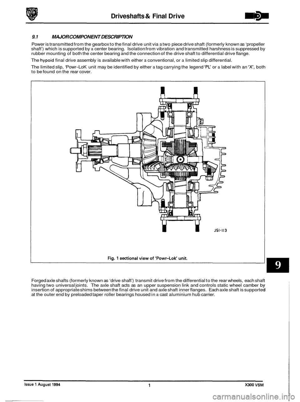
9.1 MAJOR COMPONENT DESCRIPTION
Power is transmitted from the gearbox to the final drive unit via a two piece drive shaft (formerly known as ‘propeller
shaft’) which is supported by a center bearing. Isolation from vibration and transmitted harshness is suppressed by
rubber mounting of both the center bearing and the connection of the drive shaft to differential drive flange.
The
hypoid final drive assembly is available with either a conventional, or a limited slip differential.
The limited slip, ‘Powr
-LoK unit may be identified by either a tag carrying the legend ’PC or a label with an ‘X, both
to be found on the rear cover.
U
Forged axle shafts (formerly known as ‘drive shaft’) transmit drive from the differential to the rear wheels, each shaft
having two universal joints. The axle shaft acts as an upper suspension link and controls static wheel camber by insertion of appropriate shims between the final drive unit and axle shaft inner flanges. Each axle shaft is supported
at the outer end by preloaded taper roller bearings housed in a cast aluminium hub carrier.
Page 191 of 521

Driveshafts & Final Drive
9.8 FINAL DRWE UNIT RENEW
SRO 51.25.13
. Disconnect vehicle battery ground lead.
. Support the vehicle at the rear and remove the rear road
wheels.
Disconnect brake pad wear sensor multi-plug at RH hub
carrier and remove tie straps from wishbone. Release
ABS speed sensors at
RH and LH hub carriers and remove
tie straps from wishbones.
. Remove rear brake calipers, see Section 12, and support
at bump stop. Disconnect main handbrake cable at com- pensator, short cables at joining piece and remove com- pensator.
. Remove fixings, FLEXIBLE coupling to differential DRIVE FLANGE.
CAUTIW: Under no circumstances must the flexible
coupling (or itsfixings) be loosened or removed
from the drive shaft flange.
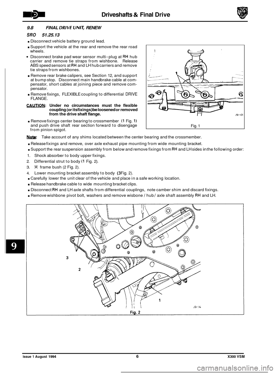
. Remove fixings center bearing to crossmember (1 Fig. 1) and push drive shaft rear section forward to disengage
from pinion spigot. Fig. 1
w: Take account of any shims located between the center bearing and the crossmember.
. Release fixings and remove, over axle exhaust pipe mounting from wide mounting bracket.
. Support the rear suspension assembly from below and remove fixings from RH and LH sides in the following order:
1. Shock absorber to body upper fixings.
2. Differential strut to body (1 Fig. 2).
3. 'A' frame bush (2 Fig. 2).
4. Lower mounting bracket assembly to body (3 Fig. 2).
. Carefully lower the unit clear of the vehicle and place in a safe working location.
. Release handbrake cable to wide mounting bracket clips.
. Disconnect RH and LH axle shafts from differential couplings, note camber shim and discard fixings.
. Remove wishbone pivot bolt, washers and remove wisbone / hub / axle shaft assembly RH and LH.
issue 1 August 1994 6 X300 VSM
Page 206 of 521

10.4.3 Diagnostic chart 2
0 Trouble
'lay at steering wheel
ieavy when stationary
Excessively heavy when
hiving, stationary effort
3K
Too easy when driving,
itationary effort OK
fffort not equal side to
;ide from center
dariation from heavy to
?asy when driving
:yclic load variation at steering wheel - 2 per
.evolution
:losely spaced cyclic
oad variation at steering
Nheel
Cause
Rack damper loose
Pinion bearing loose
Worn intermediate shaft joint
Worn suspension joint
Loose lower column 'pinch' bolt
Transducer not closed
Transducer not closed
- ground short
Transducer not closed
- no feed voltage
Transducer not closed
- defective cable
SCM defective
Delivery pressure or flow too low
Internal rack leakage
tire pressures low
Transducer open too early
Transducer open too early, incorrect SCM
h/Pe
Transducer open too early, incorrect
speedometer signal
Rack 'reaction limitation valve' CLOSED
or setting incorrect
Transducer not open (no oil flow)
Transducer not open, SCM faulty
Transducer not open, incorrect speedom
-
eter signal
Rack 'reaction limiting valve' OPEN or
setting incorrect
Low pressure pipe 'flattened' or re
-
stricted
Blocked reservoir filter
tire pressure high
Rack check valve leak
Rotary valve blockage Incorrect lower column assembly, see
'Cyclic load variations'
Incorrect speedometer signal
Transducer cable
/ connection faulty or
grounded
Lower column universal joint fitting error
Rack damper too tight
Remedy
Renew rack
Renew rack
Renew joint
Renew joint
Tighten to specification
Inspect and check for debris
Renew transducer*
Investigate and repair
Renew cable
Renew module*
Renew pump
Renew rack
Set to specification
Renew transducer*
Renew
SCM*
Renew speedometer transmitter*
Renew rack
Inspect and check for debris
Renew
SCM*
Renew speedometer transmitter*
Renew rack
Renew pipe
Renew filter
Set to specification
Renew rack
Renew rack
Rectify as required
Renew speedometer transmitter*
Investigate and repair
Verify that the lower column assembly is
correct for that drive.
RH and LH assem- blies MUST NOT be interchanged due to
joint phase differences
Renew rack
W: Items marked * should be validated using EDM test procedures.
X300 VSM 7 Issue 1 August 1994
Page 210 of 521

Suspension Systems
. .
SECTION CON TENTS
Subsection Tjf/e
.
SRO
I to IV ........... Preliminary Pages ................................................................... i
11.1 ............. Introduction ........................................................................\
. 1
11.2 ............. Front Suspension. Description ......................................... ..
Page
11.3 ............. Rearsuspension. Description .......................................................... 2
11.4.1
............ Diagnosis & Testing. Tire Wear ......................................................... 3
11.4.2
............ Diagnosis & Testing. Vibration & Roughness .............................................. 3
11.4.3
............ Diagnosis & Testing. Front End Inspection ................................................ 4
11.4.4 ............ Diagnosis & Testing. Upper/Lower Ball Joint Inspection ................................... 4
11.4.5
............ Diagnosis & Testing. Damper Inspection ................................................. 4
11.4.6
............ Diagnosis & Testing. Rear Suspension Inspection .......................................... 5
11.4.7. ........... Diagnosis & Testing. Vehicle Inspection .................................................. 5
11.4 ............. Diagnosis & Testing .................................................................. 3
. 1 1.4.8 ............ Diagnosis & Testing. Diagnostic Procedure Chart ............ ...
. .
........ .....
-
I X300 VSM i Issue 1 August 1994
.
............. 1
............. 6
Page 211 of 521
1. SERVICE TOOLS & EQUIPMENT
Illustration
Not illustrated
Jaguar Number
JDID
JD 60
JDIOO
JD115
JD133
JD135
JD143
JD143-1
50143-2
JD143-3
Description
Hub Remover Rear Suspension
Nishbone Upper Bush Remover
1 Replacer
Remover Steering Arm and Swivel
Hub Ball Pins
Spring Compressor Front Suspension
Camber Tie Down Link (Front)
RemoverIRenewer Front Damper
Lower Bush
Remover
1 Renewer Suspension
Bushes (Main
Tool)
Adaptor Ring Front Sub Frame Rear
Bushes
Anvil adapter
Adaptor Remover
1 Renewer
Suspension Bushes
Issue 1 August 1994 ii X300 VSM
Page 212 of 521
Suspension Systems
Not illustrated
1. SERVICE TOOLS & EQUIPMENT (continued)
JD199
0
Fixing
To be issued
Tightening Torque
(Nm)
JD199-1 Not i II ustrated
Description US98
LM Multi - purpose grease
Molib Alloy
PI907 No1
Molykote 11 1
Lower damper bolt
Wishbone to crossmember fulcrum shaft
Stabilizer mounting bushes
& rear damper top
guide bush
Caliper to carrier bolts
/ guide pins
Description
Notes
Adaptor Remover / Renewer
Suspension Bushes (Bottom Front
Wishbone Inner)
____~ ~ Spring
Compressor Rear Suspension
Damper Retaining Tie Rear
Suspension
Adaptor
Replacer Rear Hub Pivot
Bearing Cup
Driver Handle
Adaptor Remover
Main Shaft Pilot
Bearing Outer Track
Impulse Extractor (slide Hammer)
UNF. Basic Tool
Notes
Issue 1 August 1994 X300 VSM iii
Page 213 of 521
Suspension Systems
Application
Camber angle front suspension
Caster angle (Same setting each side of vehicle)
Wheel alignment
Specification
+0.3' to - 0.8'
3.0' to 6.0'
5'Toe-in f 10'
Note: Geometry is to be checked/set using the mid-laden setting-links. Setting height should correspond to thefol- lowing dimensions:
Front 153 f 5mm under front crossbeam (AJ16) Front 143 f 5mm under front crossbeam (V12) Rear 160 f 5mm under rear edge of 'A' frame
Issue 1 August 1994 iv X300 VSM