1994 JAGUAR XJ6 low beam
[x] Cancel search: low beamPage 19 of 521

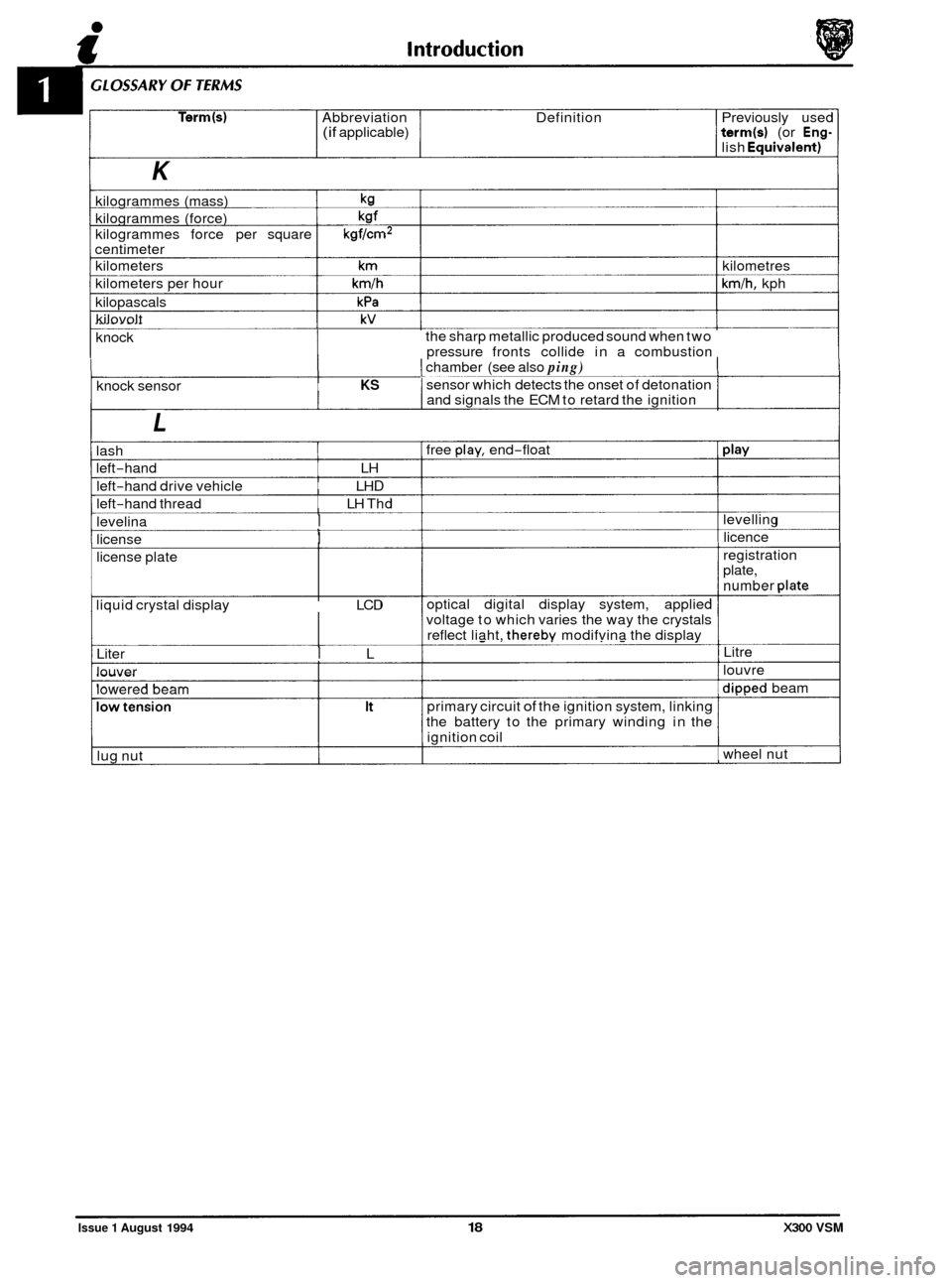
Term(s) Abbreviation Definition Previously used (if applicable) term(s) (or Eng- lish Eauivalent)
K
kilogrammes (mass) kg
kilogrammes (force) kgf
kilogrammes force per square kgf/cm2 centimeter
kilometers
km kilometres
kilometers per hour
km/h km/h, kph
kilopascals
kPa
kilovolt kV
knock
I
the sharp metallic produced sound when two
pressure fronts collide in a combustion
1 chamber (see also ping)
I sensor which detects the onset of detonation I knock sensor KS I and signals the ECM to retard the ignition I
L
lash
left
-hand LH
left
-hand drive vehicle LH D
left-hand thread LH Thd
levelina
I
license I
license plate
liquid crystal display LCD
Liter
I L
louver
lowered beam
lug nut free
play, end-float
optical digital display system, applied
voltage to which varies the way the crystals
reflect liaht,
thereby modifvina the display
primary circuit
of the ignition system, linking
the battery to the primary winding in the
ignition coil levelling
licence
registration
plate,
number
date
Litre
louvre
diooed beam
wheel nut
Issue 1 August 1994 18 X300 VSM
Page 199 of 521

@ Steering
Description
Retinax A grease
Power steering hydraulic
fluid
'11. SERVICE MATERIALS
U- Notes
Front hub bearings and seals
Dexron 2E ATF minimum (or equivalent) See
Sub Section IV Service
Data
See Sub Section
IV Service
Data
Application
Front hub end-float
Front hub bearing grease
- Quantity
Toe
-in 12 cylinder
Toe
-in 6 cylinder
Steering system capacity
Steering system operating pressure
Steering system level checking frequency
Drive belt tension (12 cylinder only)
Steering
rack turns lock to lock
Drive belt tension measuring point
Specification
0,025 to 0,08 mm
4 ml in each race
Oo 5' + or - 10' underside of front crossbeam 143mm
from ground level
Oo 5' + or - 10' underside of front crossbeam 153mm
from ground level
Approx
1 liter from dry
100> 110 bar
16,000
km
2,83
Burroughs method - New belt 790 N; If tension falls
below 270 N reset at 630 N
Clavis method - New belt 114 to 120 Hz; If tension falls
below 70 Hz reset at 87 to 93 Hz
For new belt, rotate engine 3 revolutions minimum and
retension
Mid
-way between crankshaft and compressor pulley
Issue 1 August 1994 iv X300 VSM
Page 213 of 521

Suspension Systems
Application
Camber angle front suspension
Caster angle (Same setting each side of vehicle)
Wheel alignment
Specification
+0.3' to - 0.8'
3.0' to 6.0'
5'Toe-in f 10'
Note: Geometry is to be checked/set using the mid-laden setting-links. Setting height should correspond to thefol- lowing dimensions:
Front 153 f 5mm under front crossbeam (AJ16) Front 143 f 5mm under front crossbeam (V12) Rear 160 f 5mm under rear edge of 'A' frame
Issue 1 August 1994 iv X300 VSM
Page 214 of 521

Suspension Systems
11.1 INTRODUCTION
This section describes the front and rear suspension systems, and also covers diagnostic procedures.
Fig. 1 Front Suspension Layout
11.2 FRONT SUSPENSION, DESCRIPTION
Theupperrearwishbone(1 Fig.l)andthe upperfrontwishbone(2 Fig.1)arepivotedon the upperfulcrum bolt (3Fig.l), passing through the front cross beam assembly. They are also fitted via an upper ball joint assembly (4 Fig.1) to a verti- cal linkaccommodating the stub axle (5 Fig.l), whereas the vertical linkisfittedvia a lower ball joint assembly (6 Fig.1) to the lower wishbone assembly.
The lower wishbone assembly comprises
a lower rear wishbone (7 Fig.l), lower front wishbone (8 Fig.l), damper (9 Fig.1) (incorporating damper bush 10 Fig.1) and spring pan (1 1 Fig.1) supporting the road spring (12 Fig.1). The lower
wishbone assembly is pivoted on the bushed lower fulcrum shaft (13 Fig.1) which also passes through thecross beam
assembly.
Both independent front suspension assemblies are linked by a stabilizer bar (14 Fig.1) which is secured to the cross
member using a fixing arrangement of mounting rubbers (15 Fig.1, clamps (16 Fig.l), nuts bolts, washers (17 Fig.1) and two link arm assemblies (18 Fig.1). Each link arm assembly is fitted to one end of the stabilizer bar and to one end
of the lower front wishbone using a fixing arrangement of bolts washers and self locking nuts.
All suspension loads, except the damper, are fed into a pressed steel crossbeam which is isolated from the body by
rubber bushes. This mounting method allows the necessary amount of compliance.
The degree
of caster is adjustable via shims positioned on either side of the upper ball joint assembly but camber is facton/ set and is not adjustable. The vertical link and the steering arm form a single forging. Cast iron hubs rotate
on twin tapered roller bearings.
X300 VSM 1 Issue 1 August 1994
Page 350 of 521

31
30
29
28 27
26
4 26 24 21 23 22 7 20 19 18 18 17 8
a
10
11
12
13
14
1s
1M-137
1. Tachometer 2. Speedometer
3. Battery Condition 4. FuelGauge 5. Oil Pressure 6. Coolant Temperature 7. Odometer /Trip Computer Display 8. Primary Warning Indicators (RED) 9. Exhaust Temperature 10. Low Oil Pressure 11. Seat Belt Not Fastened 12. Boot Open 13. DoorOpen 14. Coolant Level 15. Air Bag Fault 16. Status / Warning Lamps
17. Hand Brake On (RED) 18. Brake System Fault (RED)
19. Main Beam On (BLUE) 20. Direction Indicator Right (GREEN) 21. Status / Warning Lamps 22. Direction Indicator Left (GREEN) 23. Traction Control Off (GREEN) 24. Transmission Sport Mode (GREEN) 25. Charging Fault (RED) 26. Check Engine (AMBER)
27. Low Fuel Level (AMBER) 28. Anti - Lock Fault (AMBER) 29. Traction Control Fail (AMBER) 30. Bulb Fail (AMBER) 31. Washer Fluid Level (AMBER) 32. Transmission Fault (AMBER)
Fig.
1 Instrument Panel, Front Mew
w: The 'Premium Unleaded Fuel Only' caution is added to the Federal Market vehicles, also 'PARK BRAKE and
'BRAKE' replace international symbols used in all other markets.
m: Six cylinder vehicle version shown; the tachometer red-line on 12 cylinder vehicles starts at 6000 RPM.
The front of the
PECUSprogrammable instrument panel features 6 analog gauges, 22 warning lamps /tell tales and
a Liquid Crystal Display (LCD), the rear of the panel accommodates two PCB mounted connectors, one 24-way
connector, one 48-way connector, one instrument panel identification label and 14 light bulbs arranged in groups of
seven on either side. Three power inputs and two ground inputs are provided for 'POWER UP' and 'POWER DOWN'
sequence, the three power inputs comprising battery, ignition and auxiliary. The instruments are protected by a
housing
/ lens assembly.
15.2.7 Gauges
The two major gauges are tachometer and speedometer, and the four minor gauges indicate battery condition, fuel
level, oil pressure and coolant temperature.
Each gauge is contained
in a sealed non-serviceable can and must be renewed as a complete unit in case of any
damage.
CAUTION: Extreme care should be exercised when renewing instrument pand components to avoid damago to the delicate indicator needles.
X300 VSM 9 Issue 1 August 1994
Page 387 of 521

Steering and Suspension
W: When checking the steering geometry, use the pull-down tools front and rear to set the ride height front and
rear to the following dimensions:
Front ride height
................................................... 153 f 5mm to underside of front
crossbeam
Rear ride height
.................................................... 160 f 5mm to underside of rear
edge of A frame
Front ride height
................................................... 143 f 5mm to underside of front
crossbeam
Rear ride height
.................................................... 160 f 5mm to underside of rear
edge of A frame
U: Sportspack derivatives whose kerb height is below the above figures can have their geometry checked at that
height.
Front Suspension
..............................................................
0
Type Independent front suspension
consisting of double wishbones
with coil springs and separate
dampers and anti
-roll bar.
Dampers
.......................................................... Telescopic, gas pressurised
Caster angle
....................................................... 3,0° to 6,0° and with opposing
wheels within Io of each other
Camberangle
...................................................... 0,3°to-0,80
Front wheel alignment .............................................. Total toe: 5 minutes in f 10 minutes
Rear Suspension
Type .............................................................. Fully independent rear suspension of double wishbone principle with
axle shaft operating as upper
wishbone incorporating coaxial
springs and dampers with optional
rear anti
-roll bar.
Camber angle
(at design ride height):
all vehicles except supercharged ................................. -0,75O f 0,4O
supercharged only -1,6O f 0,4O ..............................................
0 Rear wheel alignment .............................................. Total toe: 15 minutes in f20
Dampers .......................................................... Telescopic, gas pressurised
minutes
Power Assisted Steering
Type .............................................................. ZF
Servotronic speed-sensitive rack
and pinion
Number
of turns lock to lock ........................................ 2,768
Turning circle: (wall to wall)
....................................................... 12,9m (42ft 4in)
(curb to curb) ...................................................... 12,4m (40ft 8in)
0
X300 VSM Issue 1 August 1994 AI-95MY 4 ~~~~
Page 395 of 521

Description Capacity Type
Door guard lamp. 12V 5W Capless long life
Flasher side repeater 12V 5W Capless long life
Fog lamp - Front. 12v 55w Halogen H3
Fog lamp
- Rear guard 12v 21w Bayonet long life
Front turn indicator
I 12v21w I Bayonet long life
Pilot lamp
I 12V 5W I Capless long life
Headlamp
I 12v55w I Halogen HI
High mounted stop lamp (where fitted). 12v Capless long life
Roof console central courtesy lamp
12V 5W Capless long life.
Roof console reading lamp
12V 6W Capless
Luggage compartment lamp
12V 5W Capless long life
License plate lamp 12V 5W Festoon
Rear turn indicator
12v 21w Bayonet yellow long
Rear quarter courtesy lamp (lower section)
12V 5W Capless long life
Rear quarter reading lamp (upper section) 12V 6W Capless
Back
-up lamp 12v 21w Bayonet long life
Stop /Tail lamp
Sun visor vanity mirror lamp
12v 1,2w Capless 286
Tail lamp 12V 5W Bayonet long life
5X5W
12V 21V 5W Twin filament bayonet long life
Indicator bulbs
Bulb Designation Holder Colour Rating
Exhaust temperature warning indicator bulb Orange 12,5V 1,2W
Low oil pressure indicator bulb
Orange 12,5V 1,2W
Seat belt warning indicator bulb
Orange 12,5V 1,2W
Boot open warning indicator bulb
Orange 12,5V 1,2W
Door open warning indicator bulb
Orange 12,5V 1,2W
Coolant level warning indicator bulb
Orange 12,5V 1,2W
Air bag fault indicator bulb Orange 12,5V 1,2W
Parking brake 'on' indicator bulb Orange 12,5V 1,2W
Brake system warning indicator bulb Orange 12,5V 1,2W
Main beam 'on' indicator bulb
Orange 12,5V 1,2W
Right turn indicator bulb Orange 12,5V 1,2W
LCD illumination bulb (right)
Orange 12,5V 1,2W
LCD illumination bulb (left) Orange 12,5V 1,2W
Left turn indicator bulb
Orange 12,5V 1,2W
Traction control 'off indicator bulb
Orange 12,5V 1,2W
Transmission sport mode indicator bulb
Orange 12,5V 1,2W
Charging fault warning bulb
Orange 12,5V 1,2W
Check engine warning indicator bulb Orange 12,5V 1,2W
0
0
0
X300 VSM Issue 1 August 1994 AI-95MY 12
Page 397 of 521

Specification
w IfrnrnJ
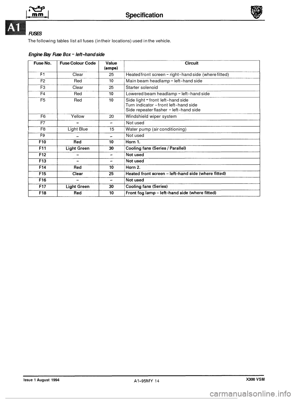
FUSES
The following tables list all fuses (in their locations) used in the vehicle.
Engine Bay Fuse Box - left-hand side
Fuse No. Fuse Colour Code Value Circuit
lamps)
F1 Clear 25 Heated front screen - right-hand side (where fitted)
F2 Red 10 Main beam headlamp - left-hand side
F3 Clear 25 Starter solenoid
F4 Red 10 Lowered beam headlamp - left-hand side
F5 Red 10 Side light - front left-hand side
Turn indicator
-front left-hand side
Side repeater flasher
- left-hand side
F6 Yellow 20 Windshield wiper system
I F8 I Light Blue
I Not used
F9 - - Not used
- - F7
15
Water pump (air conditioning) I - -
-l
X300 VSM Issue 1 August 1994 AI-95MY 14