Page 708 of 1640

Recovery
Only use service equipment that is U.L.-listed and is cer-
tified to meet the requirements of SAE J2210 to remove
HFC-134a (R-134a) from the air conditioning system.
CAUTION: Exposure to air conditioner refrigerant
and lubricant vapor or mist can irritate eyes, nose
and throat. Avoid breathing the air conditioner
refrigerant and lubricant vapor or mist.
If accidental system discharge occurs, ventilate work
area before resuming service.
R-134a service equipment or vehicle air conditioning sys-
tem should not be pressure tested or leak tested with
compressed air.
Some mixtures of air and R-134a have
been shown to be combustible at elevated pressures
and can result in fire or explosion causing injury or
property damage. Never use compressed air to pres-
sure test R-134a service equipment or vehicle air
conditioning systems.
Additional health and safety information may be obtained
from the refrigerant and lubricant manufactures.
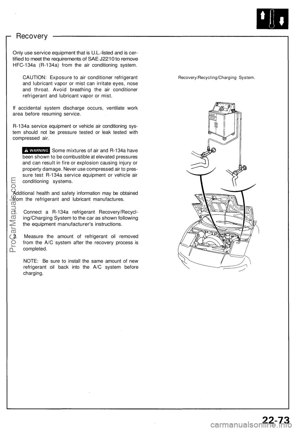
1. Connect a R-134a refrigerant Recovery/Recycl-
ing/Charging System to the car as shown following
the equipment manufacturer's instructions.
2. Measure the amount of refrigerant oil removed
from the A/C system after the recovery process is
completed.
NOTE: Be sure to install the same amount of new
refrigerant oil back into the A/C system before
charging.
Recovery/Recycling/Charging System.ProCarManuals.com
Page 709 of 1640

Heater-Evaporator Unit
Replacement
SRS components are located in this area. Review the SRS
component locations, precautions, and procedures in the
SRS section (24) before performing repairs or service.
1.
Remove
the
blower
unit
(see
page
22-67 ('93-'96),
63('91-'92)).
2. When the engine is cool, drain the engine coolant from the radiator (see section 10).
Do not remove the radiator cap when
the engine is hot; the engine coolant is under
pressure and could severely scald you.
CAUTION: Engine coolant will damage paint. Quick-
ly rinse any spilled engine coolant off painted sur-
faces.
3. Disconnect the heater valve cable from the heater valve.
4.
Disconnect
the
heater hoses. Engine cootant
will
run out when the hoses are disconnected, drain it
into a clean drip pan.
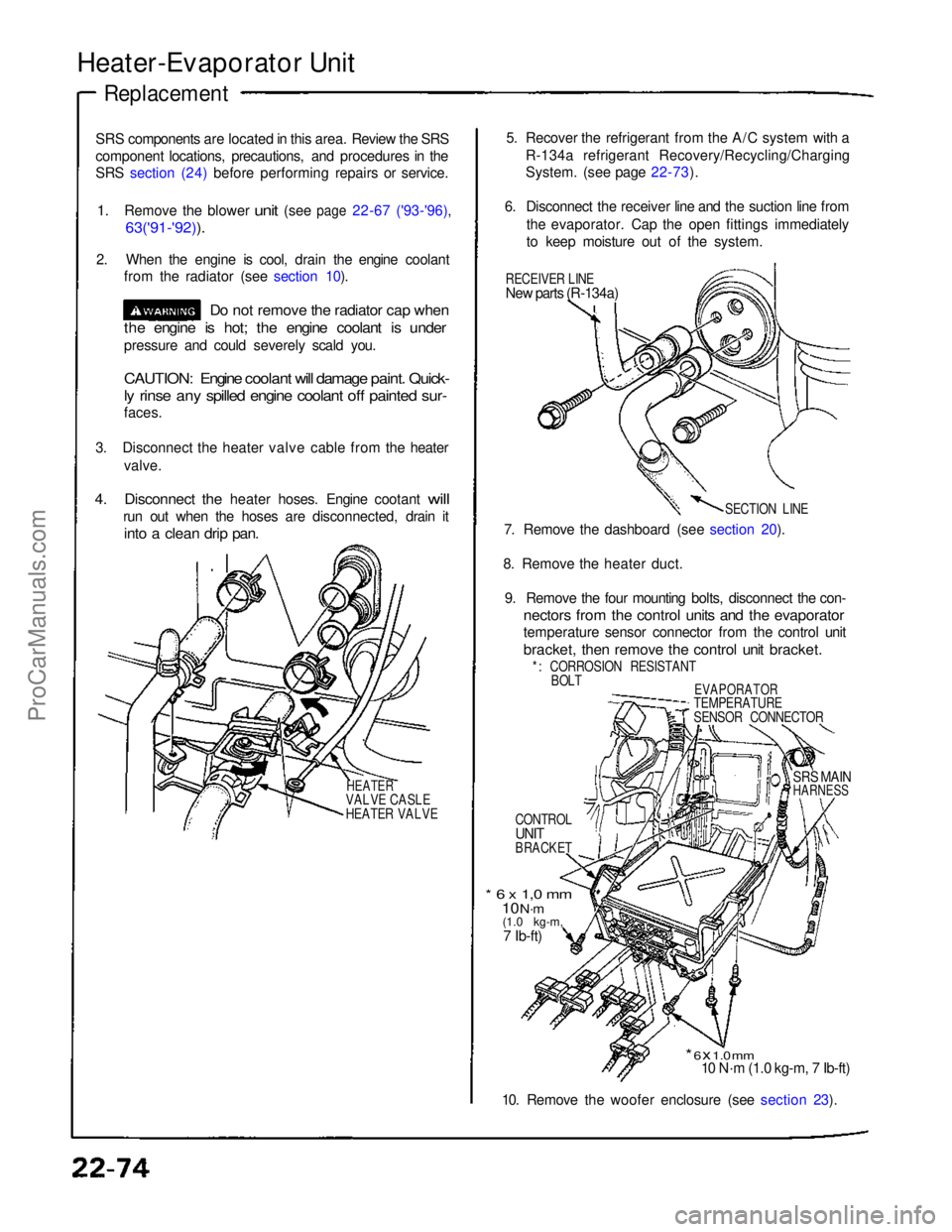
HEATER
VALVE CASLE
HEATER VALVE
5. Recover the refrigerant from the A/C system with a
R-134a refrigerant Recovery/Recycling/Charging
System. (see page 22-73).
6. Disconnect the receiver line and the suction line from the evaporator. Cap the open fittings immediately
to keep moisture out of the system.
RECEIVER LINE
New parts (R-134a)
SECTION LINE
7. Remove the dashboard (see section 20).
8. Remove the heater duct. 9. Remove the four mounting bolts, disconnect the con-
nectors from the control units and the evaporator
temperature sensor connector from the control unit
bracket, then remove the control unit bracket.
*: CORROSION RESISTANT BOLT
EVAPORATOR
TEMPERATURE
SENSOR CONNECTOR
CONTROL
UNIT
BRACKET
SRS MAIN
HARNESS
* 6 x 1,0 mm
10 N·m
(1.0 kg-m,
7 Ib-ft)
* 6 x 1.0 mm
10 N·m (1.0 kg-m, 7 Ib-ft)
10. Remove the woofer enclosure (see section 23).ProCarManuals.com
Page 725 of 1640

A/C System Service
Evacuation
Only use service equipment that is U.L.-listed and is cer-
tified to meet the requirements of SAE J2210 to remove
HFC-134a (R-134a) from the air conditioning system.
CAUTION: Exposure to air conditioner refrigerant
and lubricant vapor or mist can irritate eyes, nose
and throat. Avoid breathing the air conditioner
refrigerant and lubricant vapor or mist.
If accidental system discharge occurs, ventilate work
area before resuming service.
R-134a service equipment or vehicle air conditioning sys-
tem should not be pressure tested or leak tested with
compressed air.
Some mixtures of air and R-134a have
been shown to be combustible at elevated pressures
and can result in fire or explosion causing injury or
property damage. Never use compressed air to pres-
sure test R-134a service equipment or vehicle air
conditioning systems.
Additional health and safety information may be obtained
from the refrigerant and lubricant manufacturers.
1. When an A/C System has been opened to the at-
mosphere, such as during installation or repair, it
must be evacuated using a R-134a refrigerant
Recovery/Recycling/Charging System. (If the
system has been open for several days, the
receiver/dryer should be replaced).
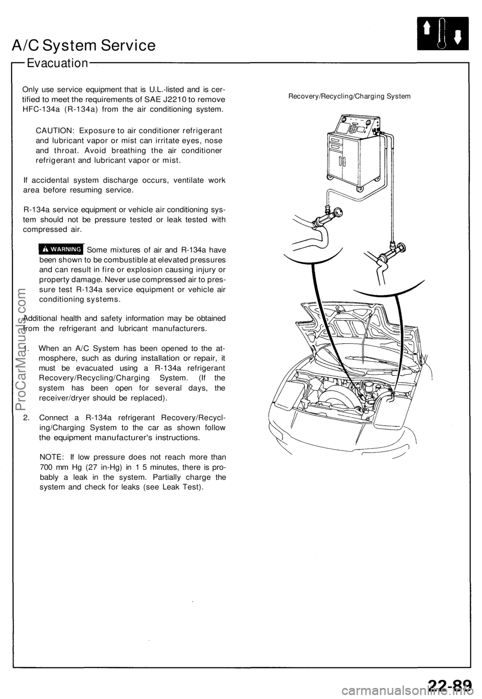
2. Connect a R-134a refrigerant Recovery/Recycl-
ing/Charging System to the car as shown follow
the equipment manufacturer's instructions.
NOTE: If low pressure does not reach more than
700 mm Hg (27 in-Hg) in 1 5 minutes, there is pro-
bably a leak in the system. Partially charge the
system and check for leaks (see Leak Test).
Recovery/Recycling/Charging SystemProCarManuals.com
Page 726 of 1640

A/C Syste m Servic e
Leak Tes t
Only us e servic e equipmen t tha t i s U.L.-liste d an d is cer -
tified to mee t th e requirement s o f SA E J221 0 to remov e
HFC-134 a (R-134a ) fro m th e ai r conditionin g system .
CAUTION : Exposur e t o ai r conditione r refrigeran t
an d lubrican t vapo r o r mis t ca n irritat e eyes , nos e
an d throat . Avoi d breathin g th e ai r conditione r
refrigeran t an d lubrican t vapo r o r mist .
I f accidenta l syste m discharg e occurs , ventilat e wor k
are a befor e resumin g service .
R-134 a servic e equipmen t o r vehicl e ai r conditionin g sys -
te m shoul d no t b e pressur e teste d o r lea k teste d wit h
compresse d air .
Som e mixture s o f ai r an d R-134 a hav e
bee n show n to b e combustibl e a t elevate d pressure s
an d ca n resul t i n fir e o r explosio n causin g injur y o r
propert y damage . Neve r us e compresse d ai r t o pres -
sur e tes t R-134 a servic e equipmen t o r vehicl e ai r
conditione r systems.
Additiona l healt h an d safet y informatio n ma y b e obtaine d
fro m th e refrigeran t an d lubrican t manufacturers .
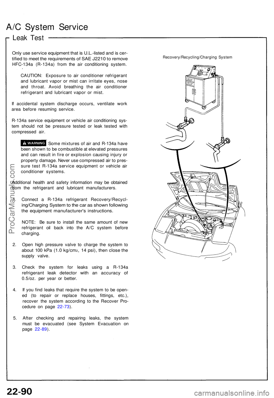
1 . Connec t a R-134 a refrigeran t Recovery/Recycl -
ing/Charging Syste m to th e ca r a s show n followin g
the equipmen t manufacturer' s instructions .
NOTE: B e sur e t o instal l th e sam e amoun t o f ne w
refrigeran t oi l bac k int o th e A/ C syste m befor e
charging .
2 . Ope n hig h pressur e valv e t o charg e th e syste m to
abou t 10 0 kP a (1. 0 kg/cm2, 1 4 psi) , the n clos e th e
suppl y valve .
3 . Chec k th e syste m fo r leak s usin g a R-134 a
refrigeran t lea k detecto r wit h a n accurac y o f
0.5/oz . pe r yea r o r better .
4 . I f yo u fin d leak s tha t requir e th e syste m to b e open -
e d (t o repai r o r replac e houses , fittings , etc.) ,
recove r th e syste m accordin g t o th e Recove r Pro -
cedur e o n pag e 22-73 ).
5 . Afte r checkin g an d repairin g leaks , th e syste m
mus t b e evacuate d (se e Syste m Evacuatio n o n
pag e 22-89 ).
Recovery/Recycling/Chargin g Syste m
ProCarManuals.com
Page 727 of 1640
Charging
Only us e servic e equipmen t tha t i s U.L.-liste d an d i s
certifie d t o mee t th e requirement s o f SA E J221 0 t o
remov e HFC-134 a (R-134a ) fro m th e ai r conditione r
system .
CAUTION : Exposur e t o ai r conditione r refrigeran t
an d lubrican t vapo r o r mis t ca n irritat e eyes , nos e
an d throat .
Avoi d breathin g th e ai r conditione r refrigeran t an d
lubrican t vapo r o r mist .
I f accidenta l syste m discharg e occurs , ventilat e wor k
are a befor e resumin g service . Additiona l healt h an d safe -
t y informatio n ma y b e obtaine d fro m th e refrigeran t an d
lubrican t manufacturers .
Refrigeran t capacity : 800-85 0 g (28-3 0 oz )
CAUTION : D o no t overcharg e th e system ; th e
compresso r wil l b e damaged .
Connec t a R-134 a refrigeran t Recovery/Recycl -
ing/Chargin g Syste m to th e ca r a s show n follo w th e
equipmen t manufacturer' s instructions .
Recovery/Recycling/Chargin g Syste m
ProCarManuals.com
Page 728 of 1640
Special Tools
Ref.
No.
Tool Number
07JAA — 001000C
07JGG — 001010A
07LAJ — PT3020A
07LAZ— SL40300
07PAZ — 0010100
Description
Antenna Nut Wrench Bait Tension Gauge
Test Harness
Test Harness C
SCS Service Connector
Qty
1
1
1
1
1
Page Reference
23-242, 244
23-109
23-132('94-'96) ('91-'93)
23-250, 307('93-'96) ('91-'92)
23-91
('94-'96) ('91-'93)
*: Included in SRS Tool Set 07MAZ - SM5000B
ProCarManuals.com
Page 741 of 1640
Under-dash Fus e Bo x
Removal/Installatio n
SRS component s ar e locate d in thi s area . Revie w th e SR S
componen t locations , precautions , an d procedure s in th e
SR S sectio n 24 befor e performin g repair s o r service .
Removal :
1. Disconnec t bot h th e negativ e cabl e an d positiv e
cabl e fro m th e battery .
2 . Carefull y remov e th e sid e sil l pa d (pul l i t up , rea r
en d first) .
3 . Remov e th e fus e bo x door .
FUSE BO XDOO R
SIDE SIL L PA D
SIDE SIL L TRI M
4. Remov e th e thre e screws , the n remov e th e sid e sil l
trim .
5. Remov e th e under-das h fus e bo x mountin g bolts . 6
. Disconnec t th e under-das h fus e bo x connectors .
NOTE : Th e SR S mai n harnes s connecto r i s doubl e
locked . T o remov e it , firs t lif t th e connecto r lid ,
the n pres s th e connecto r ta b dow n an d pul l th e
connecto r out .
TAB
SR S MAI N HARNES S
7. Tak e ou t th e under-das h fus e box .
ProCarManuals.com
Page 744 of 1640
Steering Loc k Removal/Installatio n
SRS component s ar e locate d in thi s area . Revie w th e SR S
componen t locations , precautions , an d procedure s i n th e
SR S sectio n 24 befor e performin g repair s o r service .
1 . Remov e th e dashboar d lowe r cover , an d disconnec t
th e connectors .
2 . Remov e th e dashboar d lowe r pad .
DASHBOAR D LOWE R
COVE R
3. Remov e th e til t cover .
DASHBOAR D LOWE RPAD
TIL T COVE R
4. Remov e th e steerin g colum n lowe r an d uppe r cov -
ers.
NOTE : B e carefu l no t t o damag e th e steerin g colum n
covers.
UPPER COVE R
LOWE R COVE R
5. Remov e th e das h lowe r frame .
DASH LOWE R FRAM E
ProCarManuals.com