Page 562 of 1640
Construction
Composition
REAR HATC HFRAMETRUNK LI D (#6000 )
HOOD(#6000 )
SIDE SIL L (#6000 )
REAR FENDE R (#6000)
Body Composite s(#5000)
DOOR (#6000 )
FRONT FENDE R (#6000 )
Types o f aluminu m alloys for pressings :
ROOF PANE L(#6000 )
ProCarManuals.com
Page 563 of 1640
Types and Materials of Exterior Resin Parts
NOTE: A standard symbol is stamped on the underside of each resin part to show the type of material used.
Example:
HONDA
>PP<
NO.
Part Name
Headlight lid
Front bumper
Front and rear skirts
Mirror
Side sill panel
Trunk ltd spoiler
Rear bumper
Fuel filler lid
Washer Tank
Replacement
see section 23
see page 20-58('93-'96) ,47('91-'92)
see pages 20-59 ('93-'96),48 ('91-'92),
61('93-'96),50('91-'92)
see page 20-20('93-96) ,19('91-'92)
see page 20-71
see page 20-66('93-'96),55('91-'92)
see page 20-60('93-'96),49('91-'92)
see page 20-68('93-'96),57('91-'92)
see page 20-59('93-'96),48('91-'92)
Material
PA6/PPE-M Polyamide/Polyphenylene ether
PBT-P Polybutylene terephthalate
PP Polypropylene
ABS Acrylonitrite butadiene styrene
PA6/PPE-M Polyamide/Polyphenylene ether
UP-G Polyster unsaturated thermoset
PBT-P Polybutylene terephthalate
PA6/PP-E Polyamide/Polyphenylene ether
PP PolypropyleneProCarManuals.com
Page 610 of 1640
Climate control unit, stereo cassete/radio and glove box removal:
Disassemble in numbered sequence.
NOTE: Remove the center console panel.
CLIMATE CONTROL
UNIT
Disconnect the connectors.
SRS UNIT
Passenger's:
STEREO
CASSETE RADIO
Disconnect the connectors.
GROUND CABLE
GLOVE BOX
Disconnect the connectors.
TRUNK LID OPENER
MAIN SWITCH
PASSENGER'S
AIRBAG
DLC
CONNECTOR
GLOVE BOX
LID
DASHBOARD LOWER
COVER (Passenger's)
Installation is the reverse of the removal procedure.
NOTE: Make sure the connectors are connected properly.ProCarManuals.com
Page 622 of 1640

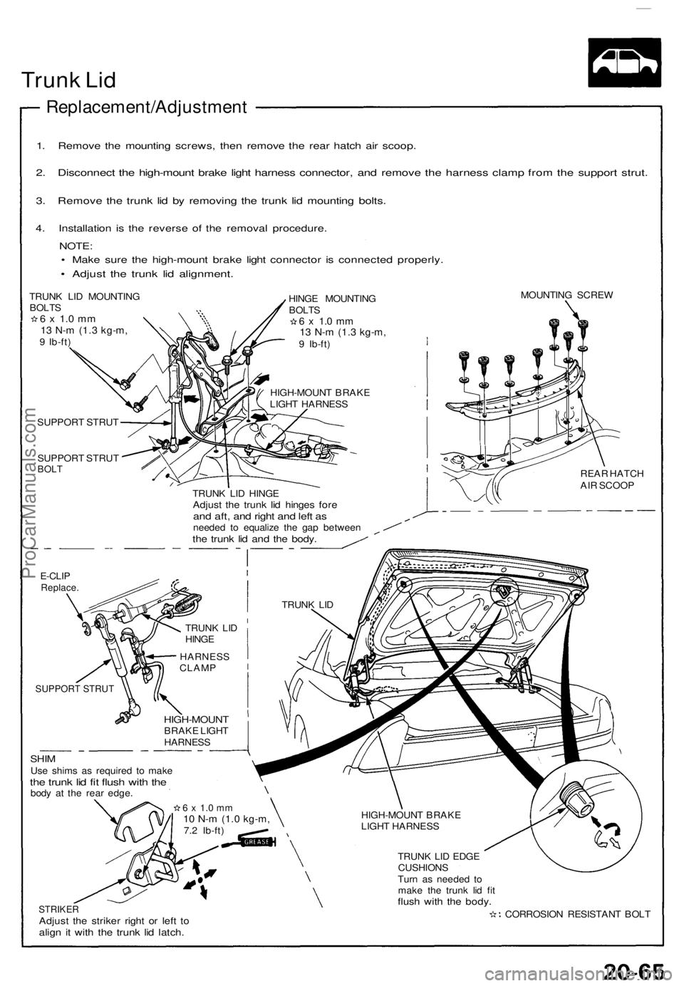
Trunk Li d
Replacement/Adjustmen t
1. Remov e th e mountin g screws , the n remov e th e rea r hatc h ai r scoop .
2. Disconnec t th e high-moun t brak e ligh t harnes s connector , an d remov e th e harnes s clam p fro m th e suppor t strut .
3. Remov e th e trun k li d b y removin g th e trun k li d mountin g bolts .
4. Installatio n i s th e revers e of the remova l procedure .
NOTE:
• Mak e sur e th e high-moun t brak e ligh t connecto r i s connecte d properly .
• Adjus t th e trun k li d alignment .
TRUNK LI D MOUNTIN GBOLTS6 x 1. 0 m m13 N- m (1. 3 kg-m ,9 Ib-ft ) HING
E MOUNTIN G
BOLT S
6 x 1. 0 m m13 N- m (1. 3 kg-m ,9 Ib-ft )
HIGH-MOUN T BRAK E
LIGH T HARNES S MOUNTIN
G SCRE W
SUPPOR T STRU T
SUPPOR T STRU T
BOLT
TRUN K LI D HING EAdjust th e trun k li d hinge s for eand aft , an d righ t an d lef t a sneede d t o equaliz e th e ga p betwee nthe trun k li d an d th e body .
REAR HATC H
AI R SCOO P
E-CLIPReplace .
HARNES S
CLAM P
SUPPORT STRUT
SHIMUse shim s a s require d t o mak ethe trun k li d fi t flus h wit h th ebod y a t th e rea r edge .
HIGH-MOUN TBRAKE LIGH THARNES S
STRIKERAdjust th e strike r righ t o r lef t t oalig n i t wit h th e trun k li d latch .
HIGH-MOUN T BRAK E
LIGH T HARNES S
TRUN K LI D EDG E
CUSHION S
Tur n a s neede d t o
mak e th e trun k li d fi t
flus h wit h th e body .
CORROSIO N RESISTAN T BOL T
6 x 1. 0 m m10 N- m (1. 0 kg-m ,7.2 Ib-ft ) TRUN
K LI D
TRUN K LI D
HING E
ProCarManuals.com
Page 623 of 1640

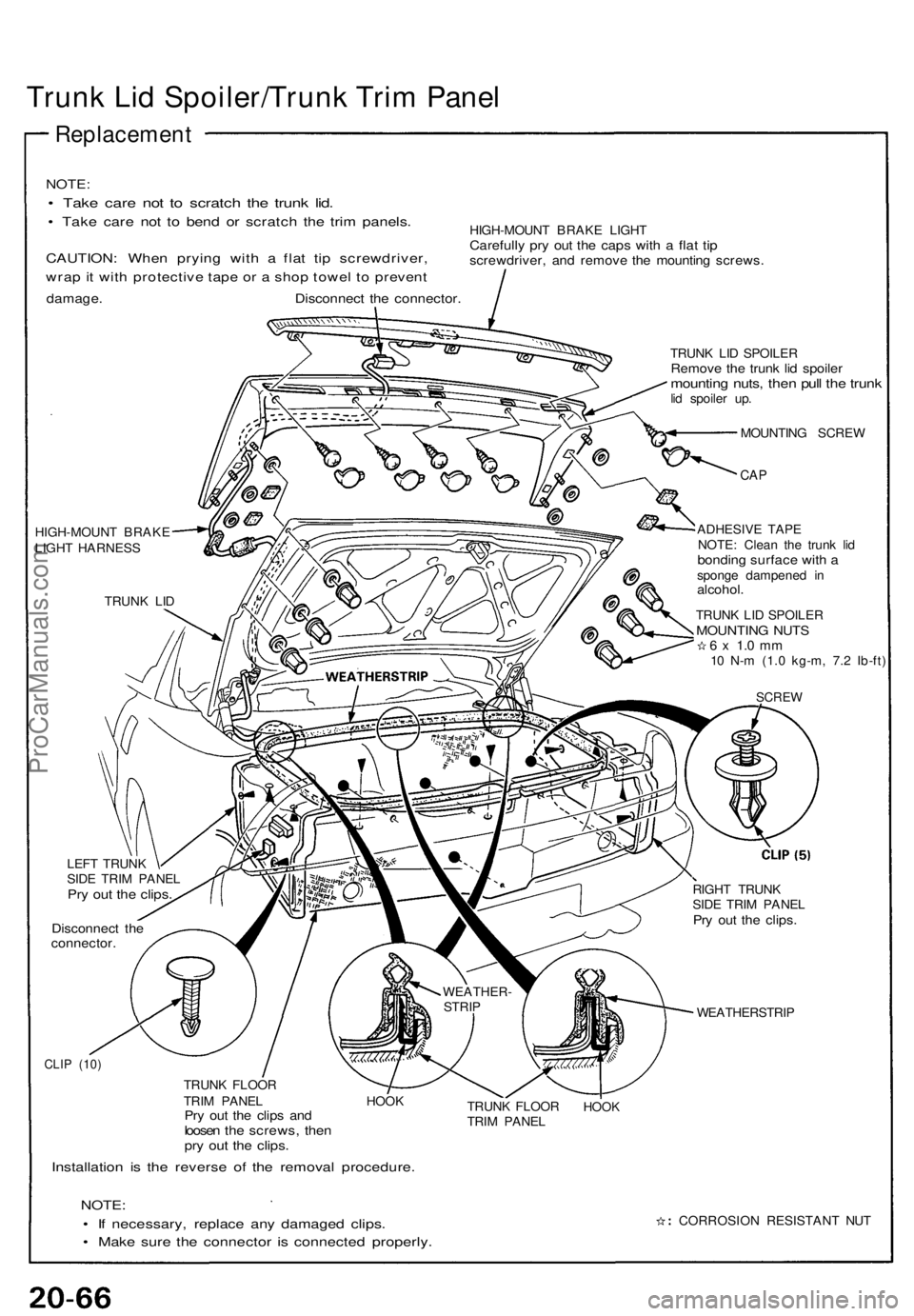
Trunk Li d Spoiler/Trun k Tri m Pane l
Replacemen t
NOTE:
• Tak e car e no t t o scratc h th e trun k lid .
• Tak e car e no t t o ben d o r scratc h th e tri m panels .
CAUTION : Whe n pryin g wit h a fla t ti p screwdriver ,
wrap it wit h protectiv e tap e o r a sho p towe l t o preven t
damage . Disconnec t th e connector .
HIGH-MOUN T BRAK E LIGH TCarefull y pr y ou t th e cap s wit h a fla t ti pscrewdriver , an d remov e th e mountin g screws .
HIGH-MOUN T BRAK E
LIGH T HARNES S
TRUN K LI D TRUN
K LI D SPOILE R
Remove th e trun k li d spoile rmountin g nuts , the n pul l th e trun klid spoile r up .
MOUNTIN G SCRE W
CAP
ADHESIV E TAP E
NOTE : Clea n th e trun k li d
bondin g surfac e wit h aspong e dampene d i nalcohol .
TRUNK LI D SPOILE RMOUNTIN G NUT S6 x 1. 0 m m10 N- m (1. 0 kg-m , 7. 2 Ib-ft )
SCRE W
LEFT TRUN K
SID E TRI M PANE L
Pry ou t th e clips .
Disconnec t th econnector .
RIGHT TRUN K
SID E TRI M PANE L
Pry ou t th e clips .
WEATHERSTRI P
CLIP (10 )
TRUN K FLOO R
TRI M PANE L HOO K
Pry ou t th e clip s an dloose n th e screws , the npry ou t th e clips .
Installatio n i s th e revers e of the remova l procedure .
NOTE:
• I f necessary , replac e an y damage d clips .
• Mak e sur e th e connecto r i s connecte d properly .
TRUNK FLOO R
TRI M PANE LHOOK
CORROSIO N RESISTAN T NU T
WEATHER
-
STRI P
ProCarManuals.com
Page 624 of 1640

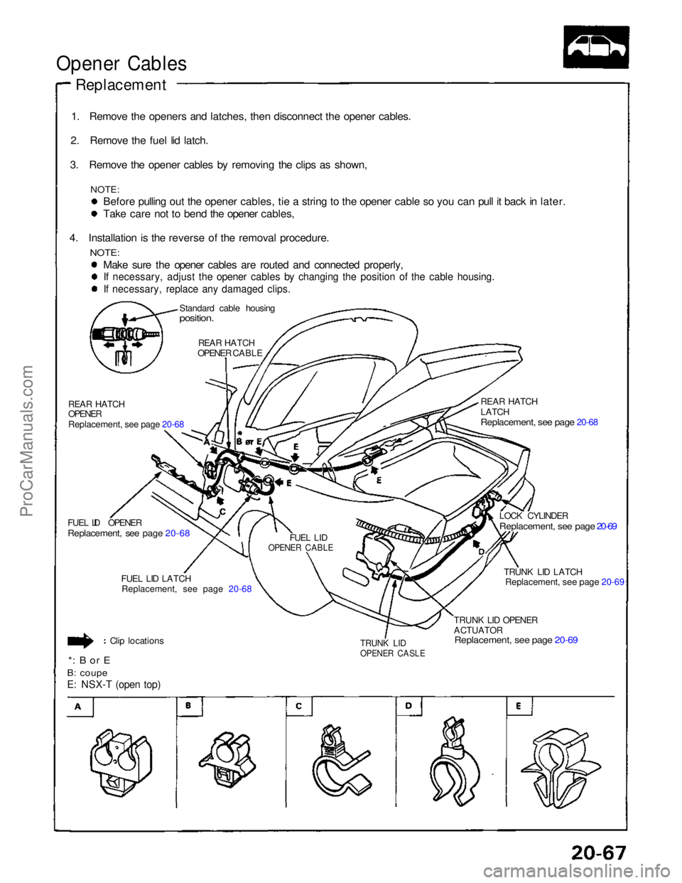
Opener Cables
Replacement
1. Remove the openers and latches, then disconnect the opener cables.
2. Remove the fuel lid latch.
3. Remove the opener cables by removing the clips as shown,
NOTE:
Before pulling out the opener cables, tie a string to the opener cable so you can pull it back in later. Take care not to bend the opener cables,
4. Installation is the reverse of the removal procedure.
NOTE:
Make sure the opener cables are routed and connected properly,
If necessary, adjust the opener cables by changing the position of the cable housing.
If necessary, replace any damaged clips.
Standard cable housing
position.
REAR HATCH
OPENER CABLE
REAR HATCH
OPENER
Replacement, see page 20-68
FUEL LID OPENER
Replacement, see page 20-68
FUEL LID
OPENER CABLE
FUEL LID LATCH
Replacement, see page 20-68
Clip locations
*: B or E
B: coupe
E: NSX-T (open top)
TRUNK LID
OPENER CASLE
TRUNK LID OPENER
ACTUATOR
Replacement, see page 20-69
TRUNK LID LATCH
Replacement, see page 20-69
LOCK CYLINDER
Replacement, see page 20-69
REAR HATCH
LATCH
Replacement, see page 20-68
ProCarManuals.com
Page 626 of 1640

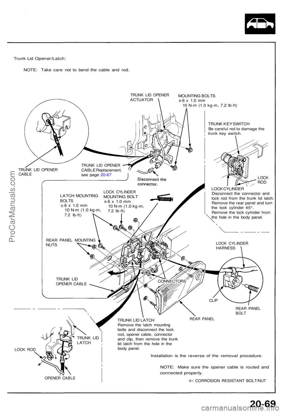
Trunk Li d Opener/Latch :
NOTE: Tak e car e no t t o ben d th e cabl e an d rod .
TRUN K LI D OPENE RACTUATO RMOUNTING BOLT S6 x 1. 0 m m10 N- m (1. 0 kg-m , 7. 2 Ib-ft )
TRUN K KE Y SWITC H
B e carefu l no t t o damag e th e
trun k ke y switch .
REAR PANE LBOLT
LOCK RO D
OPENE R CABL E
Installatio n i s th e revers e of the remova l procedure .
NOTE: Mak e sur e th e opene r cabl e i s route d an d
connecte d properly .
CORROSIO N RESISTANT BOLT/NUT
TRUNK LI DLATC H
REAR PANE L
CLIP
TRUN K LI D LATC H
Remov e th e latc h mountin g
bolt s an d disconnec t th e loc k
rod , opene r cable , connecto r
an d clip , the n remov e th e trun k
li d latc h fro m th e hol e i n th e
bod y panel .
CONNECTOR S
LOCK CYLINDE RHARNESS
TRUNK LI DOPENE R CABL E
REAR PANE L MOUNTIN GNUTSLATC
H MOUNTIN G
BOLTS6 x 1. 0 m m10 N- m (1. 0 kg-m ,7.2 Ib-ft )
LOCK CYLINDE RMOUNTING BOL T6 x 1. 0 m m10 N- m (1. 0 kg-m ,7.2 Ib-ft )
TRUN K LI D OPENE RCABLE Replacement ,
se e pag e 20-6 7TRUN K LI D OPENE RCABLE
LOCK CYLINDE R
Disconnec t th e connecto r an d
loc k ro d fro m th e trun k li d latch .
Remov e th e rea r pane l an d tur n
th e loc k cylinde r 45° .
Remov e th e loc k cylinde r fro m
th e hol e i n th e bod y panel .
LOCKROD
ProCarManuals.com
Page 633 of 1640
Construction
Features
The reinforce d part s ar e locate d a s shown .
: Reinforce d parts .
DASHBOAR D
UPPE R CROS S
MEMBE R
UPPERSTIFFENE R ROO
F PANE L
TRUNK FRON T
CROS S MEMBE R
FLOO R CROS S
MEMBE R
BULKHEA D
CENTE R PILLA R
UPPERREINFORCEMEN T
CENTE R PILLA R
LOWE R REINFORCEMEN T
LOWE R STIFFENE R
FRON T SID E
SIL L EXTENSIO N
LOWERREINFORCEMEN T Uppe
r
Reinforcemen t
Uppe r stiffene r
Uppe r patc h
Oute r pane l Inne
r pilla r
Front Pilla r Sectio n
SIDE SIL L
STIFFENE R
ProCarManuals.com