1991 ACURA NSX change time
[x] Cancel search: change timePage 414 of 1640
System Description
Function and Operation
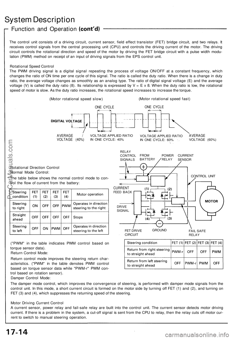
The control unit consists of a driving circuit, current sensor, field effect transistor (FET) bridge circuit, and two relays. It
receives control signals from the central processing unit (CPU) and controls the driving current of the motor. The driving
circuit controls the rotational direction and speed of the motor by driving the FET bridge circuit with a pulse width modu-
lation (PWM) method on receipt of an input of driving signals from the EPS control unit.
Rotational Speed Control
The PWM driving signal is a digital signal repeating the process of voltage ON/OFF at a constant frequency, which
changes the ratio of ON time per one cycle of this signal. The ratio is called the duty ratio. When there is a change in duty
ratio, the average voltage changes as smoothly as an analog type. The ratio of digital signal voltage (E) and the average
voltage (V) is called the duty ratio (8). Its relationship is expressed by V = E x 8. When the duty ratio is low, the rotational
speed of motor is slow. As the duty ratio increases, the rotational speed increases to increase the torque.
(Motor rotational speed slow)
ONE CYCLE
(Motor rotational speed fast)
ONE CYCLE
AVERAGE /
VOLTAGE (40%)
VOLTAGE APPLIED RATIO
IN ONE CYCLE: 40%
RELAY
CONTROL
SIGNALS
VOLTAGE APPLIED RATIO
IN ONE CYCLE: 60%
AVERAGE
VOLTAGE (60%)
FROM
BATTERY
POWER
RELAY
CURRENT
SENSOR
Rotational Direction Control
Normal Mode Control:
The table below shows the normal control mode to con-
trol the flow of current from the battery:
CURRENT
FEED BACK
DRIVE
SIGNAL
FET DRIVE
CIRCUIT
GROUND
FAIL SAFE
RELAY
("PWM" in the table indicates PWM control based on
torque sensor data).
Return Control Mode:
Return control mode improves the steering return char-
acteristics. ("PWM" in the table denotes PWM control
based on torque sensor data while "PWM-r" PWM con-
trol based on rotation sensor).
Damper Control Mode:
The damper mode control, which improves the convergence of steering, is performed with damper mode signals from the
control unit. In this mode, a short current circuit is formed on the motor side by turning off FET (1) and (2), and turning on
FET (3) and (4), which suppresses the returning speed of the steering.
Motor Driving Current Control
A current sensor, power relay and fail-safe relay are built into the control unit. The current sensor detects motor driving
current. If there is a problem in the system, a cut-off signal is sent from the CPU to relay, then the relay cuts off motor cur-
rent to switch to manual steering operation.
CONTROL UNITProCarManuals.com
Page 502 of 1640
Brake Booste r
Tests
Functiona l Tes t
1. Wit h th e engin e stopped , depres s th e brak e peda l
severa l time s t o deplet e th e vacuu m reservoir , the n
depres s th e peda l har d an d hol d i t fo r 1 5 seconds .
I f th e peda l sinks , eithe r th e maste r cylinde r i s
bypassin g internally , o r th e brak e syste m (maste r
cylinder , lines , modulator , proportionin g valve , o r
calipers ) ar e leaking .
2 . Star t th e engin e wit h th e peda l depressed . I f th e pe -
da l sink s slightly , th e vacuu m booste r i s operatin g
normally , i f th e peda l heigh t doe s no t vary , th e
booste r o r chec k valv e i s faulty .
3 . Wit h th e engin e running , depres s th e brak e peda l
lightly . Appl y jus t enoug h pressur e t o hol d bac k au -
tomati c transmissio n creep . I f th e brak e peda l sink s
mor e tha n 2 5 m m (1. 0 in. ) i n thre e minutes , th e
maste r cylinde r i s faulty . A sligh t chang e i n peda l
heigh t whe n th e A/ C compresso r cycle s o n an d of f
i f normal . (Th e A/ C compresso r loa d change s th e
vacuu m availabl e t o th e booster. )
Leak Tes t
1. Depres s th e brak e peda l wit h th e engin e running ,
the n sto p th e engine . I f th e peda l heigh t doe s no t
var y whil e depresse d fo r 3 0 seconds , th e vacuu m
booste r i s OK . I f th e peda l rises , th e booste r i s faulty .
2 . Wit h th e engin e stopped , depres s th e brak e peda l
severa l time s usin g norma l pressure . Whe n th e pe -
da l i s firs t depressed , i t shoul d b e low . O n consecu -
tiv e applications , th e peda l heigh t shoul d graduall y
rise . I f th e peda l positio n doe s no t vary , chec k th e
booste r chec k valve .
Booste r Chec k Valv e Tes t
1. Disconnec t th e brak e booste r vacuu m hos e a t th e
booste r o r a t th e booste r sid e o f th e valve .
2 . Star t th e engin e an d le t i t idle . Ther e shoul d b e vacu -
um . I f n o vacuu m is available , th e chec k valv e is no t
workin g properly . Replac e th e chec k valv e an d
retest .
ProCarManuals.com
Page 980 of 1640
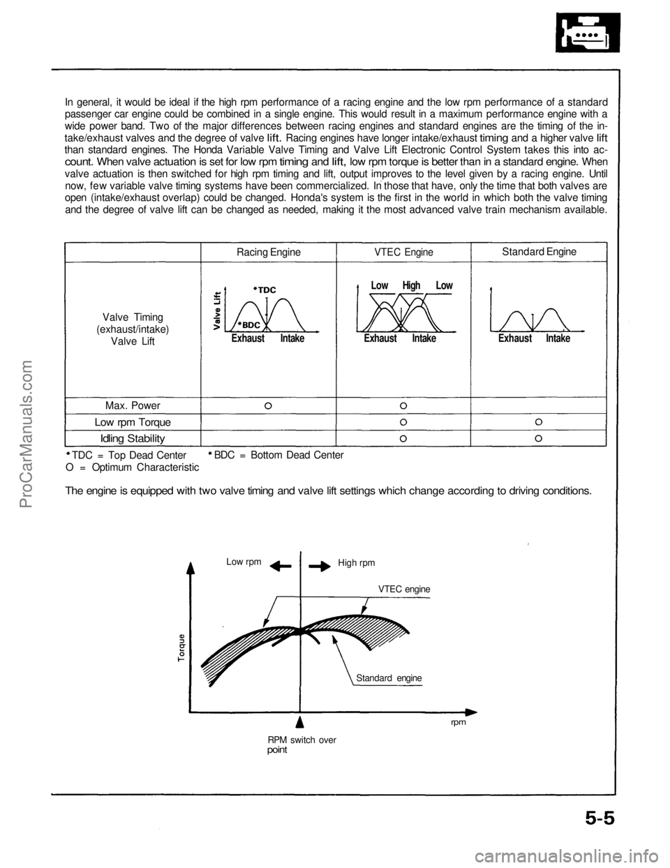
In general, it would be ideal if the high rpm performance of a racing engine and the low rpm performance of a standard
passenger car engine could be combined in a single engine. This would result in a maximum performance engine with a
wide power band. Two of the major differences between racing engines and standard engines are the timing of the in-
take/exhaust valves
and the
degree
of
valve
lift.
Racing engines have longer intake/exhaust
timing
and a
higher valve
lift
than standard engines. The Honda Variable Valve Timing and Valve Lift Electronic Control System takes this into ac-
count.
When
valve
actuation
is set for low rpm
timing
and
lift,
low rpm
torque
is
better
than
in a
standard
engine.
When
valve actuation is then switched for high rpm timing and lift, output improves to the level given by a racing engine. Untilnow, few variable valve timing systems have been commercialized. In those that have, only the time that both valves are
open (intake/exhaust overlap) could be changed. Honda's system is the first in the world in which both the valve timing
and the degree of valve lift can be changed as needed, making it the most advanced valve train mechanism available.
Valve Timing
(exhaust/intake) Valve Lift Racing Engine
Exhaust Intake
VTEC Engine
Low High Low
Exhaust Intake
Standard Engine
Exhaust Intake
Max. Power
Low rpm Torque
Idling Stability
TDC = Top Dead Center
Low rpm
High rpm
VTEC engine
RPM switch over
point
Standard engine
rpm
BDC = Bottom Dead Center
O = Optimum Characteristic
The engine is equipped with two valve timing and valve lift settings which change according to driving conditions.ProCarManuals.com
Page 1331 of 1640
System Description
Power Unit
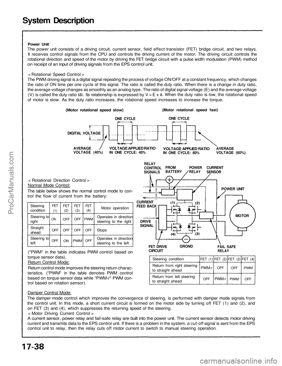
The power unit consists of a driving circuit, current sensor, field effect transistor (FET) bridge circuit, and two relays.
It receives control signals from the CPU and controls the driving current of the motor. The driving circuit controls the
rotational direction and speed of the motor by driving the FET bridge circuit with a pulse width modulation (PWM) method
on receipt of an input of driving signals from the EPS control unit.
< Rotational Speed Control >
The PWM driving signal is a digital signal repeating the process of voltage ON/OFF at a constant frequency, which changes the ratio of ON time per one cycle of this signal. The ratio is called the duty ratio. When there is a change in duty ratio,
the average voltage changes as smoothly as an analog type. The ratio of digital signal voltage (E) and the average voltage
(Motor rotational speed fast)
ONE CYCLE
AVERAGE
VOLTAGE (60%)
VOLTAGE APPLIED RATIO
IN ONE CYCLE: 60%
CURRENT
SENSOR
POWER
RELAY
FROM
BATTERY
RELAY
CONTROL
SIGNALS
VOLTAGE APPLIED RATIO
IN ONE CYCLE: 40%
AVERAGE
VOLTAGE (40%)
(Motor rotational speed slow)
DIGITAL VOLTAGE
ONE CYCLE
CURRENT
FEED BACK
DRIVE
SIGNAL
< Rotational Direction Control >
Normal Mode Control:
The table below shows the normal control mode to con-
trol the flow of current from the battery:
("PWM" in the table indicates PWM control based on
torque sensor data). Return Control Mode:
Return control mode improves the steering return charac-
teristics. ("PWM" in the table denotes PWM control based on torque sensor data while "PWM-r" PWM con-
trol based on rotation sensor).
POWER UNIT
FET DRIVE
CIRCUIT
GROND
FAIL SAFE
RELAY
Damper Control Mode:
The damper mode control which improves the convergence of steering, is performed with damper mode signals from
the control unit. In this mode, a short current circuit is formed on the motor side by turning off FET (1) and (2), and on FET (3) and (4), which suppresses the returning speed of the steering. < Motor Driving Current Control >
A current sensor, power relay and fail-safe relay are built into the power unit. The current sensor detects motor driving
current and transmits data to the EPS control unit. If there is a problem in the system, a cut-off signal is sent from the EPS
control unit to relay, then the relay cuts off motor current to switch to manual steering operation. (V) is called the duty ratio
of motor is slow. As the duty ratio increases, the rotational speed increases to increase the torque. When the duty ratio is low, the rotational speed
Its relationship is expressed by V = E x
Steering
condition Steering to
rightStraight
ahead
Steering to
left
OFFOFF
ON
FET
(1)
FET
(2)
FET
(3)
FET
(4)
OFF
OFF
OFF
ON
OFF
PWM
OFF
OFF
PWM
Motor operation
Stops
Operates in direction
steering to the left Operates in direction
steering to the right
Steering condition
Return from right steering
to straight ahead
Return from left steering
to straight ahead
FET (1)
PWM-r
OFF
FET (2)
OFF
PWM-r
FET (3)
OFF
PWM
OFF
PWM
FET (4)
MOTORProCarManuals.com
Page 1557 of 1640
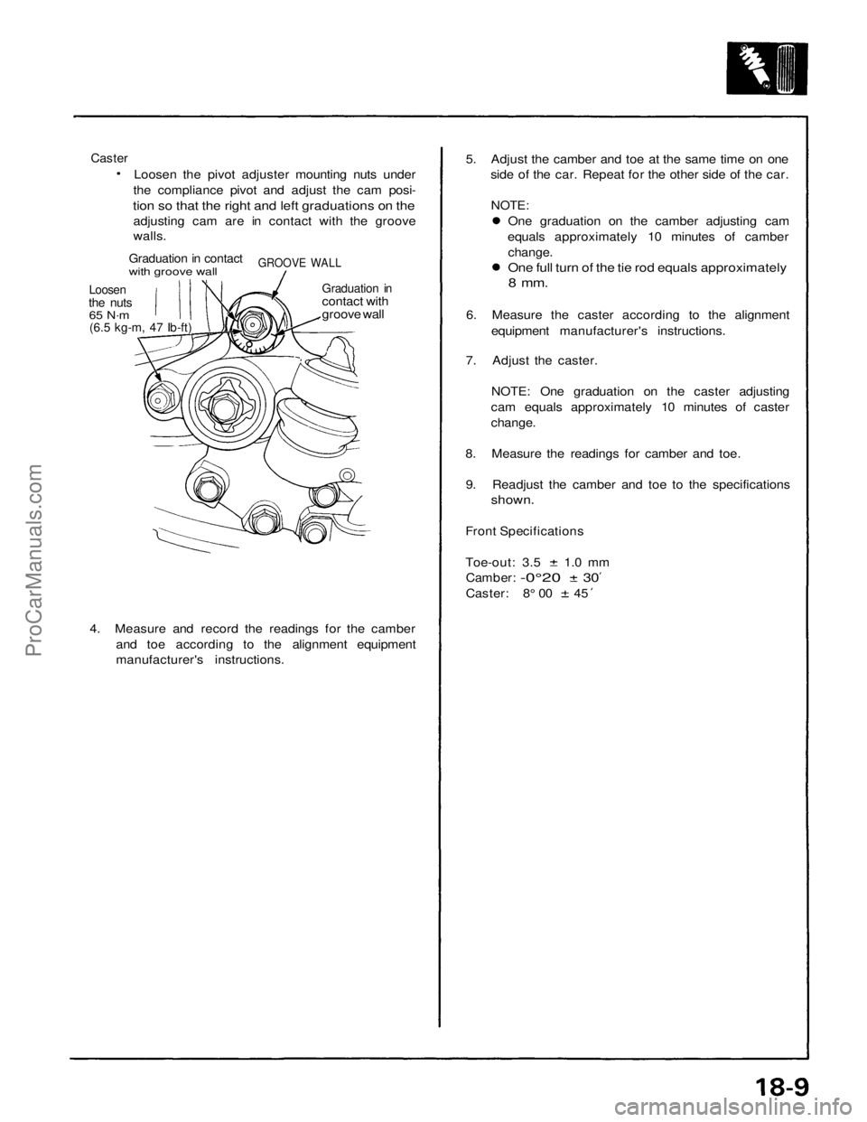
Caster
Loosen the pivot adjuster mounting nuts under
the compliance pivot and adjust the cam posi-
tion so that the right and left graduations on the
adjusting cam are in contact with the groove
walls.
Graduation in contact
with groove wall
GROOVE WALL
Loosen
the nuts
65 N·m
(6.5 kg-m, 47 Ib-ft)
Graduation in
contact with
groove wall
4. Measure and record the readings for the camber
and toe according to the alignment equipment
manufacturer's instructions.
5. Adjust the camber and toe at the same time on one
side of the car. Repeat for the other side of the car.
NOTE:
One graduation on the camber adjusting cam
equals approximately 10 minutes of camber
change.
One full turn of the tie rod equals approximately
8 mm.
6. Measure the caster according to the alignment
equipment manufacturer's instructions.
7. Adjust the caster.
NOTE: One graduation on the caster adjusting
cam equals approximately 10 minutes of caster
change.
8. Measure the readings for camber and toe.
9. Readjust the camber and toe to the specifications
shown.
Front Specifications
Toe-out: 3.5 1.0 mm
Camber:
-0°20
30
Caster: 8° 00 45ProCarManuals.com