1991 ACURA NSX check engine light
[x] Cancel search: check engine lightPage 230 of 1640
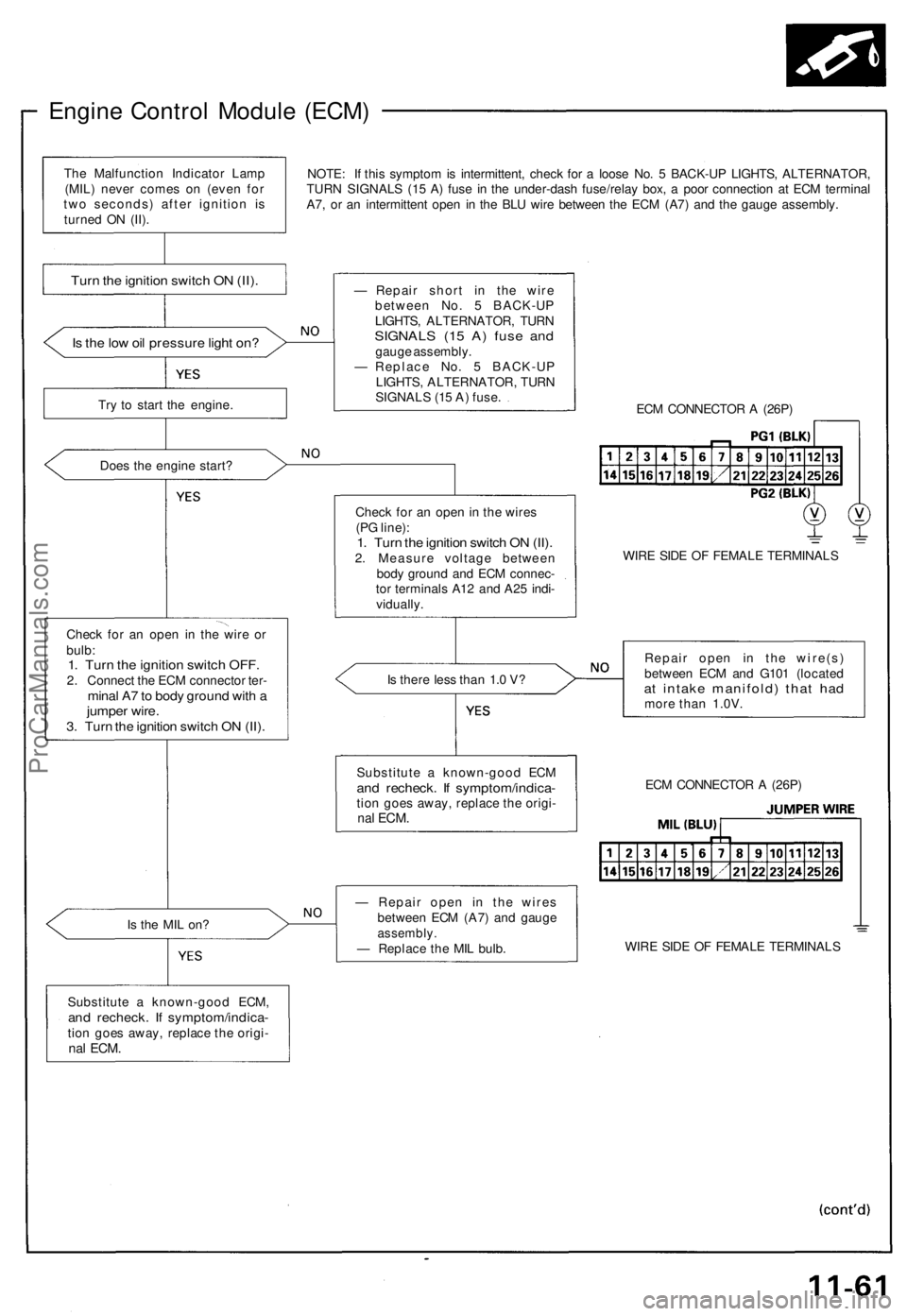
Engine Control Module (ECM)
NOTE: If this symptom is intermittent, check for a loose No. 5 BACK-UP LIGHTS, ALTERNATOR,
TURN SIGNALS (15 A) fuse in the under-dash fuse/relay box, a poor connection at ECM terminal
A7, or an intermittent open in the BLU wire between the ECM (A7) and the gauge assembly.
Is the low oil pressure light on?
Try to start the engine.
Does the engine start?
Check for an open in the wire or
bulb:
1. Turn the ignition switch OFF.
2. Connect the ECM connector ter-
minal A7 to body ground with a
jumper wire.
3. Turn the ignition switch ON (II).
Is the MIL on?
Substitute a known-good ECM,
and recheck. If symptom/indica-
tion goes away, replace the origi-
nal
ECM.
— Repair short in the wire
between No. 5 BACK-UP
LIGHTS, ALTERNATOR, TURN
SIGNALS (15 A) fuse and
gauge assembly.
— Replace No. 5 BACK-UP
LIGHTS, ALTERNATOR, TURN
SIGNALS (15 A) fuse.
ECM CONNECTOR A (26P)
Check for an open in the wires
(PG line):
1. Turn the ignition switch ON (II).
2. Measure voltage between
body ground and ECM connec-
tor terminals A12 and A25 indi-
vidually.
WIRE SIDE OF FEMALE TERMINALS
Is there less than 1.0 V?
Repair open in the wire(s)
between ECM and G101 (located
at intake manifold) that had
more than 1.0V.
— Repair open in the wires
between ECM (A7) and gauge
assembly.
— Replace the MIL bulb.
WIRE SIDE OF FEMALE TERMINALS
ECM CONNECTOR A (26P)
Substitute a known-good ECM
and recheck. If symptom/indica-
tion goes away, replace the origi-
nal
ECM.
Turn the ignition switch ON (II).
The Malfunction Indicator Lamp
(MIL) never comes on (even for
two seconds) after ignition is
turned ON (II).ProCarManuals.com
Page 238 of 1640
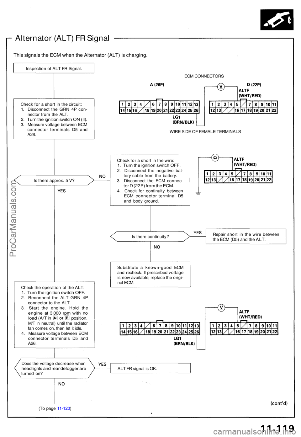
Alternator (ALT ) F R Signa l
This signal s th e EC M whe n th e Alternato r (ALT ) i s charging .
Inspection o f AL T F R Signal .
ECM CONNECTOR S
WIR E SID E O F FEMAL E TERMINAL S
Chec k fo r a shor t i n th e wire :
1. Tur n th e ignitio n switc h OFF .2. Disconnec t th e negativ e bat -
ter y cabl e fro m th e battery .
3 . Disconnec t th e EC M connec -
tor D (22P ) fro m th e ECM .4. Chec k fo r continuit y betwee n
EC M connecto r termina l D 5
an d bod y ground .
I
s ther e approx . 5 V ?
Chec
k fo r a shor t i n th e circuit :
1 . Disconnec t th e GR N 4 P con -
necto r fro m th e ALT .
2. Tur n th e ignitio n switc h O N (II) .3. Measur e voltag e betwee n EC M
connecto r terminal s D 5 an d
A26 .
Is ther e continuity ? Repai
r shor t i n th e wir e betwee nthe EC M (D5 ) and th e ALT .
Substitut e a known-goo d EC M
an d recheck . I f prescribe d voltag e
i s no w available , replac e th e origi -
nal ECM .Chec k th e operatio n o f th e ALT :1. Tur n th e ignitio n switc h OFF .2. Reconnec t th e AL T GR N 4 P
connecto r t o th e ALT .
3 . Star t th e engine . Hol d th e
engin e a t 3,00 0 rp m wit h n oloa d (A/ T in position ,M/T in neutral ) unti l th e radiato r
fa n come s on , the n le t i t idle .
4 . Measur e voltag e betwee n EC M
connecto r terminal s D 5 an d
A26.
Doe s th e voltag e decreas e whe nhead light s an d rea r defogge r ar eturne d on ? AL
T F R signa l i s OK .
(T o pag e 11-120 )
ProCarManuals.com
Page 420 of 1640
Troubleshooting Precautions
EPS Indicator Light
Under normal conditions, the EPS indicator light in the gauge assembly comes on when the ignition switch is turned to
the ON (II) position, then goes off after the engine is started. This indicates that the bulb and its circuits are operating cor-
rectly. If there is any trouble in the system, the EPS indicator light turns on during driving, and the power steering assist is
turned off. When the EPS indicator light comes on, the control unit memorizes the DTC. In this case, the control unit does
not activate the EPS system after the engine starts again but it keeps the EPS indicator light on.
Diagnostic Trouble Code (DTC)
• The lowest DTC is indicated first.
• The DTCs continue blinking until the ignition switch is turned off.
• The DTCs are erased from the control unit when the EPS control unit VBU power supply or connector is disconnected.
• The EPS system can be reset and the control unit's memory can be erased by disconnecting the CLOCK (7.5 A) fuse for
more than ten seconds.
Self-diagnosis:
The CPU (central processing unit) controls the following when it detects a problem during self-diagnosis:
1. Turns the EPS indicator light ON to alert the driver.
2. Power assist stops, and normal manual steering operation resumes (except DTC 21 and DTC 33).
3. The EPS control unit memorizes the diagnostic trouble code (DTC).
4. After the DTC is stored in the control unit, the CPU stops self-diagnosis.
Troubleshooting:
• Before starting the troubleshooting, clear the DTC by disconnecting the CLOCK (7.5 A) fuse for ten seconds or more,
and test-drive the car. Check that the symptom of the trouble appears again, and then troubleshoot. If the problem is an
intermittent problem, the system does not become active after the engine starts even though the problem is solved.
• When both EPS indicator light and A/T "D" indicator light come on, perform the A/T troubleshooting first.
• When the customer's reported problem cannot be verified in the car, ask the customer about the conditions when the
EPS indicator light came ON, then test-drive the car under those conditions, if possible. If the EPS indicator light does
not come ON during the test, check for loose connections or poor contacts at the connectors by wiggling the harness,
etc.
• The connector terminal numbers are viewed from the wire side for the female terminals and from the terminal side for
the male terminals.
• After the repair, test-drive the car and check that the EPS indicator light does not come ON again during the test. (Refer
to the Symptom-to-System Chart for diagnostic period.)ProCarManuals.com
Page 521 of 1640
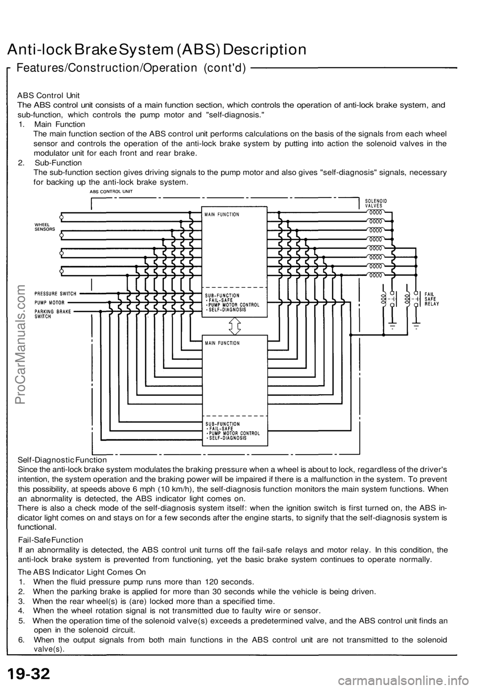
Anti-lock Brake System (ABS) Description
Features/Construction/Operation (cont'd)
ABS Control Unit
The ABS control unit consists of a main function section, which controls the operation of anti-lock brake system, and
sub-function, which controls the pump motor and "self-diagnosis."
1. Main Function
The main function section of the ABS control unit performs calculations on the basis of the signals from each wheel
sensor and controls the operation of the anti-lock brake system by putting into action the solenoid valves in the
modulator unit for each front and rear brake.
2. Sub-Function
The sub-function section gives driving signals to the pump motor and also gives "self-diagnosis" signals, necessary
for backing up the anti-lock brake system.
Self-Diagnostic Function
Since the anti-lock brake system modulates the braking pressure when a wheel is about to lock, regardless of the driver's
intention, the system operation and the braking power will be impaired if there is a malfunction in the system. To prevent
this possibility, at speeds above 6 mph (10 km/h), the self-diagnosis function monitors the main system functions. When
an abnormality is detected, the ABS indicator light comes on.
There is also a check mode of the self-diagnosis system itself: when the ignition switch is first turned on, the ABS in-
dicator light comes on and stays on for a few seconds after the engine starts, to signify that the self-diagnosis system is
functional.
Fail-Safe Function
If an abnormality is detected, the ABS control unit turns off the fail-safe relays and motor relay. In this condition, the
anti-lock brake system is prevented from functioning, yet the basic brake system continues to operate normally.
The ABS Indicator Light Comes On
1. When the fluid pressure pump runs more than 120 seconds.
2. When the parking brake is applied for more than 30 seconds while the vehicle is being driven.
3. When the rear wheel(s) is (are) locked more than a specified time.
4. When the wheel rotation signal is not transmitted due to faulty wire or sensor.
5. When the operation time of the solenoid valve(s) exceeds a predetermined valve, and the ABS control unit finds an
open in the solenoid circuit.
6. When the output signals from both main functions in the ABS control unit are not transmitted to the solenoid
valve(s).ProCarManuals.com
Page 531 of 1640
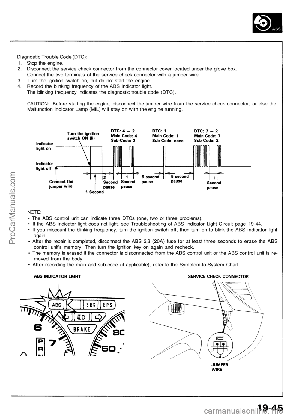
Diagnostic Trouble Code (DTC):
1. Stop the engine.
2. Disconnect the service check connector from the connector cover located under the glove box.
Connect the two terminals of the service check connector with a jumper wire.
3. Turn the ignition switch on, but do not start the engine.
4. Record the blinking frequency of the ABS indicator light.
The blinking frequency indicates the diagnostic trouble code (DTC).
CAUTION: Before starting the engine, disconnect the jumper wire from the service check connector, or else the
Malfunction Indicator Lamp (MIL) will stay on with the engine running.
NOTE:
• The ABS control unit can indicate three DTCs (one, two or three problems).
• If the ABS indicator light does not light, see Troubleshooting of ABS Indicator Light Circuit page 19-44.
• If you miscount the blinking frequency, turn the ignition switch off, then turn on to blink the ABS indicator light
again.
• After the repair is completed, disconnect the ABS 2,3 (20A) fuse for at least three seconds to erase the ABS
control unit's memory. Then turn the ignition key on again and recheck.
• The memory is erased if the connector is disconnected from the ABS control unit or the ABS control unit is re-
moved from the body.
• After recording the main and sub-code (if applicable), refer to the Symptom-to-System Chart.ProCarManuals.com
Page 558 of 1640
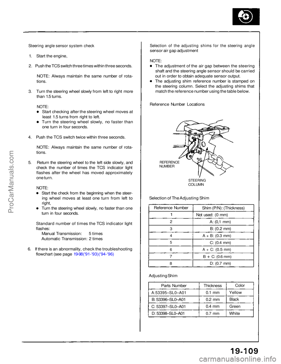
Steering angle sensor system check
1. Start the engine,
2. Push the TCS switch three times within three seconds.
NOTE: Always maintain the same number of rota-
tions.
3. Turn the steering wheel slowly from left to right more than 1.5 turns.
NOTE:
Start checking after the steering wheel moves at
least 1.5 turns from right to left.
Turn the steering wheel slowly, no faster than
one turn in four seconds.
4. Push the TCS switch twice within three seconds. NOTE: Always maintain the same number of rota-
tions.
5. Return the steering wheel to the left side slowly, and check the number of times the TCS indicator light
flashes after the wheel has moved approximately
one turn.
NOTE:
Start the check from the beginning when the steer-ing wheel moves at least one turn from left to
right, Turn the steering wheel slowly, no faster than one
turn in four seconds.
Standard number of times the TCS indicator light
flashes:
Manual Transmission: 5 times
Automatic Transmission: 2 times
6. If there is an abnormality, check the troubleshooting flowchart (see page 19-98('91-'93)('94-'96)
Selection of the adjusting shims for the steering angle
sensor air gap adjustment
NOTE:
The adjustment of the air gap between the steeringshaft and the steering angle sensor should be carried
out in order to obtain adequate sensor output.
The adjusting shim reference number is stamped on
the steering column. Select the adjusting shims that match the reference number using the table below.
Reference Number Locations
REFERENCE
NUMBER
STEERING
COLUMN
Selection of The Adjusting Shim
Adjusting Shim Parts Number
A:53395–SL0–A01
B: 53396–SL0–A01
C: 53397–SL0–A01
D: 53398–SL0–A01
Thickness
0.1 mm
0.2 mm
0.4 mm
0.7 mm
Color
Yellow
Black
Green
White
Reference Number
1
2
3
4
5
6
7
8
Shim (P/N): (Thickness)
Not used: (0 mm)
A:
(0,1
mm)
B:
(0.2
mm)
A + B:
(0.3
mm)
C:
(0.4
mm)
A + C:
(0.5
mm)
B + C:
(0.6
mm)
D:
(0.7
mm)ProCarManuals.com
Page 860 of 1640
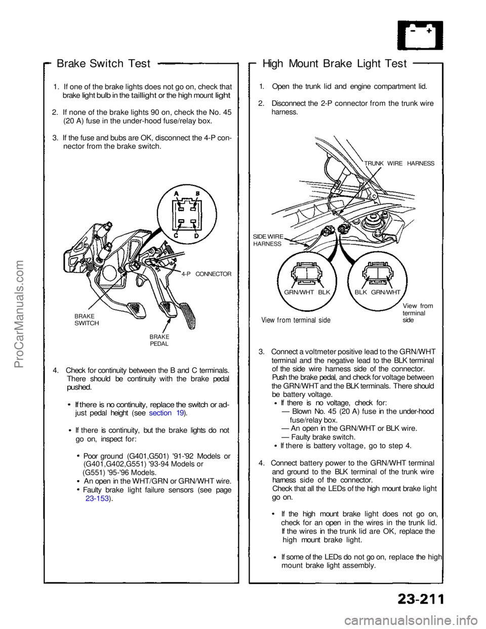
(G551) '95-'96 Models.
(G401,G402,G551) '93-94 Models or
Brake Switch
Test
1
.
If one of the brake lights does not go on, check that
brake
light bulb in the taillight or the high mount light
2
.
If none of the brake lights 90 on, check the No. 45 (2
0
A) fuse in the under-hood fuse/relay box.
3
.
If the fuse and bubs are OK, disconnect the 4-P con- necto
r
from the brake switch.
4-P CONNECTOR
BRAKE
SWITCH
BRAKE
PEDAL
4. Check for continuity between the B and C terminals. There should be continuity with the brake pedal
pushed.
If there is no continuity, replace the switch or ad-
just pedal height (see section 19).
If there is continuity, but the brake lights do not
go on, inspect for:
Poor ground (G401,G501) '91-'92 Models or
An open in the WHT/GRN or GRN/WHT wire. Faulty brake light failure sensors (see page 23-153). High Mount Brake Light Test
1. Open the trunk lid and engine compartment lid.
2. Disconnect the 2-P connector from the trunk wire
harness.
TRUNK WIRE HARNESS
SIDE WIRE
HARNESS
View from terminal side
View from
terminal
side
3. Connect a voltmeter positive lead to the GRN/WHT terminal and the negative lead to the BLK terminalof the side wire harness side of the connector.
Push the brake pedal, and check for voltage between
the GRN/WHT and the BLK terminals. There should be battery voltage. If there is no voltage, check for:
— Blown No. 45 (20 A) fuse in the under-hood
fuse/relay box.
— An open in the GRN/WHT or BLK wire.
— Faulty brake switch.
If there is battery voltage, go to step 4.
4. Connect battery power to the GRN/WHT terminal and ground to the BLK terminal of the trunk wireharness side of the connector.
Check that all the LEDs of the high mount brake light
go on.
If the high mount brake light does not go on,check for an open in the wires
in the trunk lid.
If the wires in the trunk lid are OK, replace the
high mount brake light.
If some of the LEDs do not go on,
replace the high
mount brake light assembly.
GRN/WHT BLK
BLK GRN/WHTProCarManuals.com
Page 1076 of 1640
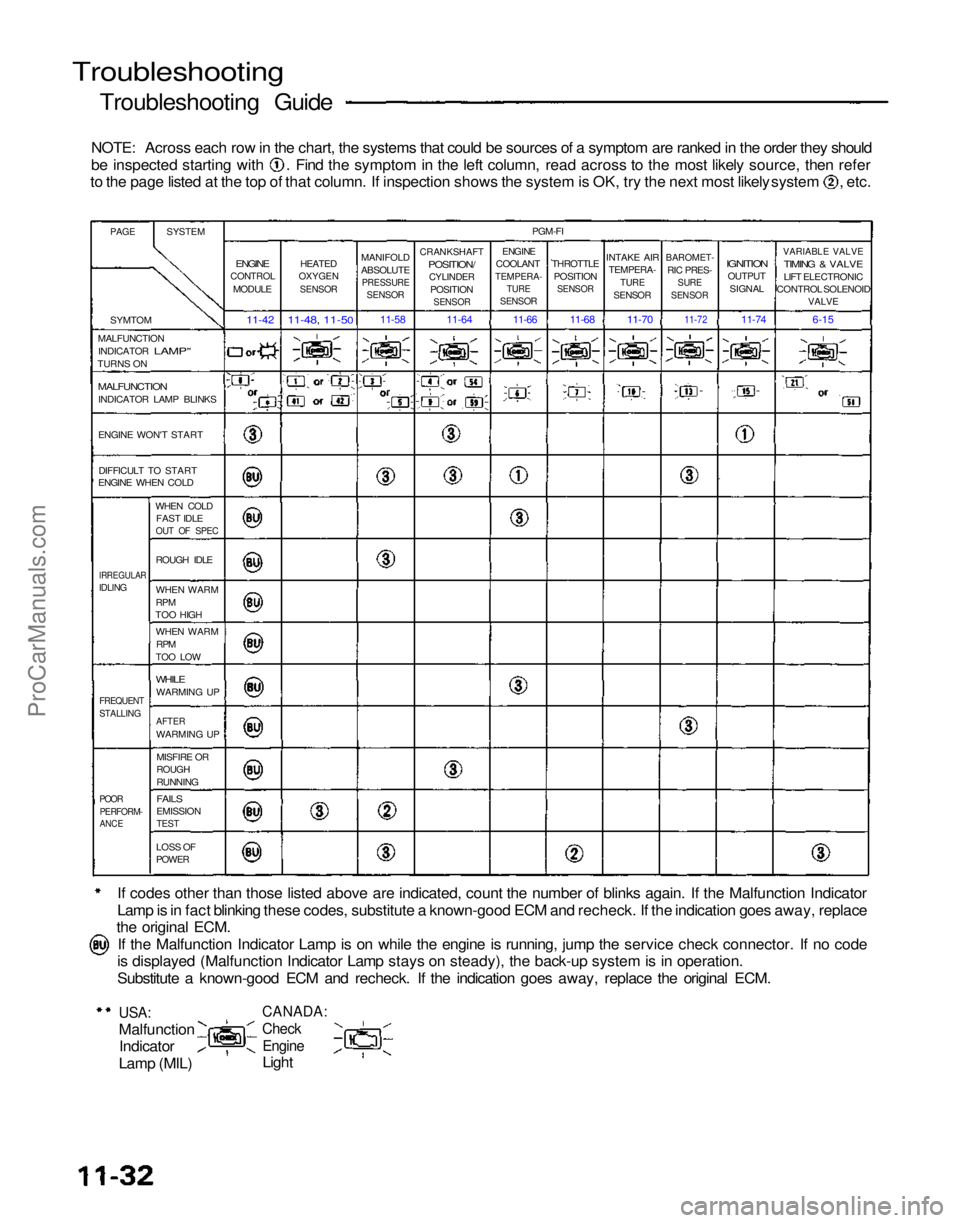
Troubleshooting
Troubleshooting Guide
NOTE: Across each row in the chart, the systems that could be sources of a symptom are ranked in the order they should be inspected starting with . Find the symptom in the left column, read across to the most likely source, then refer
to the page listed at the top of that column. If inspection shows the system is OK, try the next most likely system , etc.
If codes other than those listed above are indicated, count the number of blinks again. If the Malfunction Indicator
Lamp is in fact blinking these codes, substitute a known-good ECM and recheck. If the indication goes away, replace
the original ECM.
If the Malfunction Indicator Lamp is on while the engine is running, jump the service check connector. If no code
is displayed (Malfunction Indicator Lamp stays on steady), the back-up system is in operation.
Substitute a known-good ECM and recheck. If the indication goes away, replace the original ECM.
USA:
Malfunction
Indicator
Lamp (MIL)
CANADA:
Check
Engine
Light
PAGE
SYSTEM
SYMTOM
MALFUNCTION INDICATOR
LAMP"
TURNS ON
MALFUNCTION
INDICATOR LAMP BLINKS
ENGINE WON'T START
DIFFICULT TO START
ENGINE WHEN COLD
WHEN COLDFAST IDLE
OUT OF SPEC
IRREGULAR
IDLING
ROUGH IDLE
WHEN WARM
RPM
TOO HIGH
WHEN WARM
RPM
TOO LOW
WHILE
WARMING UP
FREQUENT
STALLING
AFTER
WARMING UP
MISFIRE OR
ROUGH
RUNNING
POOR
PERFORM-
ANCE
FAILS
EMISSION
TEST
LOSS OF
POWER
ENGINE
CONTROL
MODULE
11-42
HEATED
OXYGEN
SENSOR
11-48, 11-50
MANIFOLD
ABSOLUTE
PRESSURE
SENSOR
11-58
CRANKSHAFT
POSITION/
CYLINDER
POSITION
SENSOR
11-64
PGM-FI
ENGINE
COOLANT
TEMPERA-
TURE
SENSOR
THROTTLE
POSITION
SENSOR
INTAKE AIR
TEMPERA-
TURE
SENSOR
BAROMET-
RIC PRES-
SURE
SENSOR
IGNITION
OUTPUT
SIGNAL
VARIABLE VALVE
TIMING & VALVE
LIFT ELECTRONIC
CONTROL SOLENOID
VALVE
6-15
11-74
11-72
11-70
11-68
11-66
ProCarManuals.com