Page 1498 of 1640

Idle Control System
Idle Speed Setting
Inspection/Adjustment
1. Start the engine and warm it up to normal operating temperature (the cooling fan comes on).
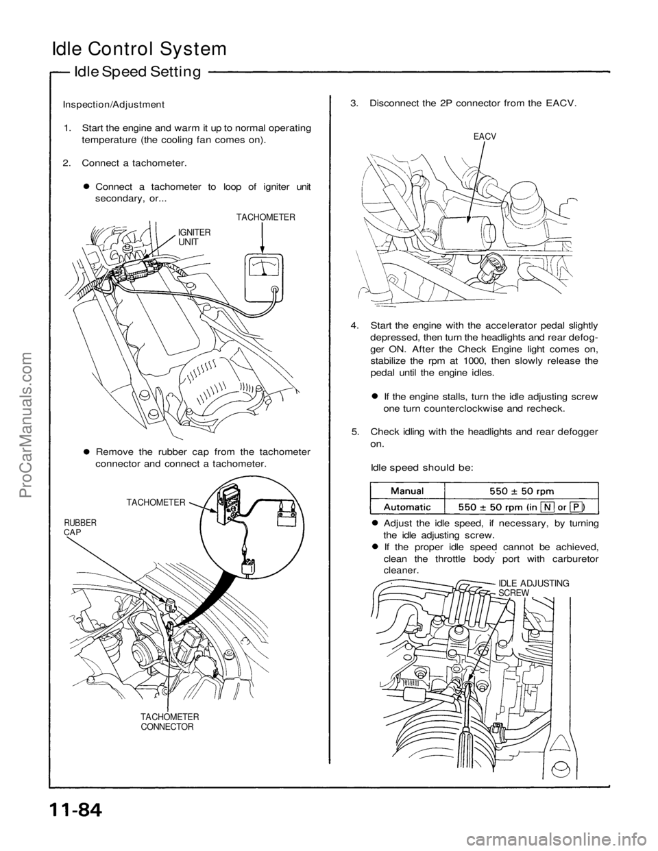
2. Connect a tachometer. Connect a tachometer to loop of igniter unit
secondary, or... 3. Disconnect the 2P connector from the EACV.
EACV
TACHOMETER
IGNITER
UNIT
4. Start the engine with the accelerator pedal slightlydepressed, then turn the headlights and rear defog-
ger ON. After the Check Engine light comes on,stabilize the rpm at 1000, then slowly release the
pedal until the engine idles. If the engine stalls, turn the idle adjusting screw
one turn counterclockwise and recheck.
5. Check idling with the headlights and rear defogger
on.
Idle speed should be:
Remove the rubber cap from the tachometer
connector and connect a tachometer.
TACHOMETER
RUBBER
CAP
Adjust the idle speed, if necessary, by turning
the idle adjusting screw. If the proper idle speed cannot be achieved,
clean the throttle body port with carburetor
cleaner.
IDLE ADJUSTING
SCREW
TACHOMETER CONNECTORProCarManuals.com
Page 1499 of 1640
6. Turn the ignition switch OFF.
7. Reconnect the 2P connector on the EACV, then
remove CLOCK fuse in the under-hood fuse/relay
box for 10 seconds to reset ECU.
8. Restart and idle the engine with no-load conditions
in which the headlights, blower fan, rear defogger,
cooling fan, and air conditioner are not operating
for one minute, then check the idle speed.
Idle speed should be:ProCarManuals.com
Page 1506 of 1640
Fuel Supply System
Pressure Regulator (cont'd)
3. Check that the fuel pressure rises when the vacuum hose from the regulator is disconnected again.
If the fuel pressure did not rise, check to see if it
rises with the fuel return hose lightly pinched.
If the fuel pressure still does not rise, replace the
pressure regulator.
Replacement
Do not smoke while working on fuel sys-
tem . Keep open flame away from work area.
1. Place a shop towel under pressure regulator, then
relieve fuel pressure (page
11-87).
2. Disconnect the vacuum hose and fuel return hose.
3. Remove the two 6 mm retainer bolts.
O-RING
Replace.
PRESSURE REGULATOR
RETURN HOSE
SHOP TOWEL
NOTE:
Replace the O-ring. When assembling the regulator, apply clean engine
oil to the O-ring and assemble it into its proper
position, taking care not to damage the O-ring.ProCarManuals.com
Page 1520 of 1640

Air Intake System
Throttle Body
Description
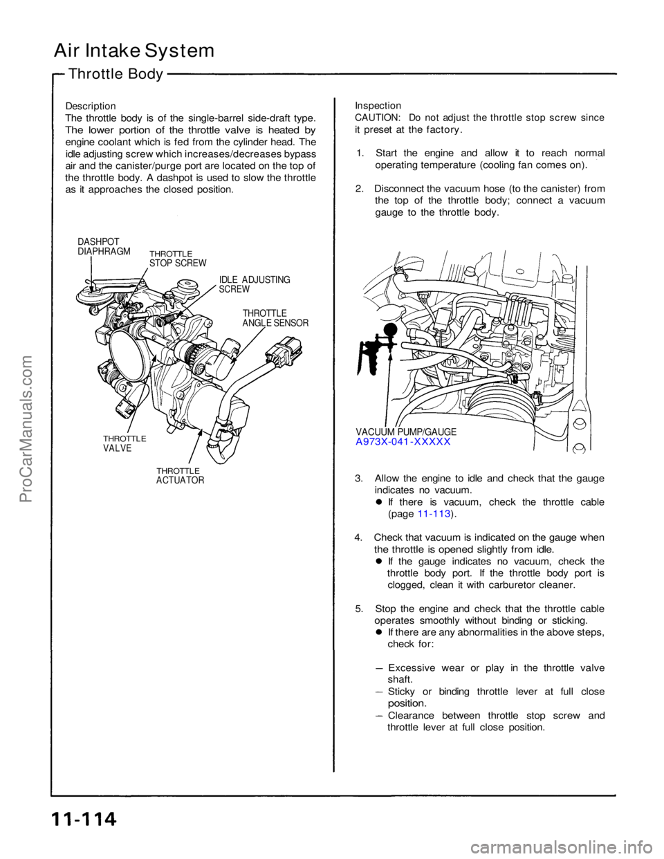
The throttle body is of the single-barrel side-draft type.
The lower portion of the throttle valve is heated by
engine coolant which is fed from the cylinder head. Theidle adjusting screw which increases/decreases bypass
air and the canister/purge port are located on the top of
the throttle body. A dashpot is used to slow the throttle as it approaches the closed position.
Inspection
CAUTION: Do not adjust the throttle stop screw since
it preset at the factory.
1. Start the engine and allow it to reach normal operating temperature (cooling fan comes on).
2. Disconnect the vacuum hose (to the canister) from the top of the throttle body; connect a vacuum
gauge to the throttle body.
DASHPOT
DIAPHRAGM
THROTTLE
STOP SCREW
IDLE ADJUSTING
SCREW
THROTTLE
ANGLE SENSOR
VACUUM PUMP/GAUGE
A973X-041 -XXXXX
THROTTLE
VALVE
THROTTLE
ACTUATOR
3. Allow the engine to idle and check that the gauge
indicates no vacuum. If there is vacuum, check the throttle cable
(page 11-113).
4. Check that vacuum is indicated on the gauge when
the throttle is opened slightly from idle.
If the gauge indicates no vacuum, check the
throttle body port. If the throttle body port is clogged, clean it with carburetor cleaner.
5. Stop the engine and check that the throttle cable operates smoothly without binding or sticking. If there are any abnormalities in the above steps,
check for:
Excessive wear or play in the throttle valve
shaft.
Sticky or binding throttle lever at full close
position.
Clearance between throttle stop screw and
throttle lever at full close position.ProCarManuals.com
Page 1528 of 1640
System Description
Tailpipe Emission
The emission control system includes a three-way catalytic converter, exhaust gas recirculation (EGR) system,
crankcase ventilation system and evaporative control
system.
The emission control system is designed to meet federal and
state emission standards.
Inspection
Do not smoke during this procedure. Keep
any open flame away from your work area.
1. Starting the engine and warm it up to normal operating temperature by driving the car on theroad.
2. Connect a tachometer.
3. Check idle speed and adjust the idle speed, if necessary (page 11-84).
4. Warm up and calibrate the CO meter according to the meter manufacturer's instructions.
5. Check idle CO with the headlights, heater blower, rear window defogger, cooling fan, and air conditioner off.
CO meter should indicate 0.1 % maximum.ProCarManuals.com
Page 1531 of 1640
Emission Control System
Positive Crankcase Ventilation System
Description The Positive Crankcase Ventilation (PCV) system is
designed to prevent blow-by gas from escaping to theatmosphere. The PCV valve contains a spring-loaded
plunger. When the engine starts, the plunger in the PCV
valve is lifted in proportion to intake manifold vacuum and
the blow-by gas is drawn directly into the intake manifold.
PCV HOSE
BLOW-BY VAPOR
FRESH AIR
PCV VALVE
Inspection
1 Check the crankcase ventilation hoses and connec- tions for leaks and clogging.
BREATHER
PIPE
2. At idle, make sure there is a clicking sound from the PCV valve when the hose between PCV valve and
intake manifold in lightly pinched with your fingers or
pliers.
If there is no clicking sound, check the PCV valve
grommet for cracks or damage. If the grommet is
OK, replace the PCV valve and recheck.
PCV VALVE
PCV HOSE
Gently pinch here
BREATHER HOSE
FRONT OF
VEHICLEProCarManuals.com
Page 1569 of 1640

Troubleshooting
Anti-lock Brake System Indicator Light
Temporary Driving Conditions:
1. The anti-lock brake system indicator light will come
on and the control unit memorizes the problem
under certain conditions.
NOTE: Problem codes are explained on pages
19 - 46.
The tire(s) adhesion is lost due to excessive cor-
nering speed.
Problem codes: 5, 5-4, 5-8. The vehicle loses traction when starting from a
stuck condition on a muddy, snowy, or sandy
road.
Problem code: 4-1, 4-2, 4-4, 4-8. When the parking brake is applied for more than
30 seconds while the vehicle is being driven.
Problem code: 2. The vehicle is driven on extremely rough road.
The anti-lock brake system is OK, if the anti-lock brake system indicator light goes off after the
engine is restarted.
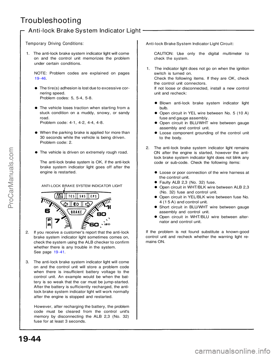
ANTI-LOCK BRAKE SYSTEM INDICATOR LIGHT
2. If you receive a customer's report that the anti-lock brake system indicator light sometimes comes on,
check the system using the ALB checker to confirm
whether there is any trouble in the system.
See page 19 - 41.
3. The anti-lock brake system indicator light will come on and the control unit will store a problem codewhen there is insufficient battery voltage to the
control unit. An example would be when the bat-
tery is so weak that the car must be jump-started. After the battery is sufficiently recharged, the anti-lock brake system indicator light will work normally
after the engine is stopped and restarted.
However, after recharging the battery, the problem
code must be cleared from the control unit's
memory by disconnecting the ALB 2,3 (No. 32)
fuse for at least 3 seconds. Anti-lock Brake System Indicator Light Circuit:
CAUTION: Use only the digital multimeter to
check the system.
1. The indicator light does not go on when the ignition switch is turned on.
Check the following items. If they are OK, check
the control unit connectors. If not loose or disconnected, install a new control
unit and recheck:
Blown anti-lock brake system indicator light
bulb.
Open circuit in YEL wire between No. 5 (10 A)
fuse and gauge assembly. Open circuit in BLU/WHT wire between gauge
assembly and control unit. Loose component grounding of the control unit
to the body.
2. The anti-lock brake system indicator light remains ON after the engine is started, however the anti-lock brake system indicator light does not blink any
code or sub-code. Check the following items:
Loose or poor connection of the wire harness at
the control unit.
Faulty ALB 2,3 (No. 32) fuse.
Open circuit in WHT/BLK wire between ALB 2,3(No. 32) fuse and control unit.
Open circuit in YEL/BLK wire between fuse No.
4 (1 5 A) and control unit.
Short circuit in BLU/WHT wire between gauge
assembly and control unit. Open circuit in WHT/BLU wire between alter-
nator and control unit.
If the problem is not found substitute a known-good
control unit and recheck whether the warning light re-
mains ON.ProCarManuals.com
Page 1570 of 1640

Comes on and remains on while running:
1. Stop the engine.
2. Turn the ignition switch on and make sure that the anti-lock brake system indicator light comes on.
3. Restart the engine and check the anti-lock brake system indicator light.
There is no problem in the anti-lock brake system, if the anti-lock brake system indicator light goes off. Go to step 4, if the anti-lock brake system indicator light remains on.
4. Stop the engine.
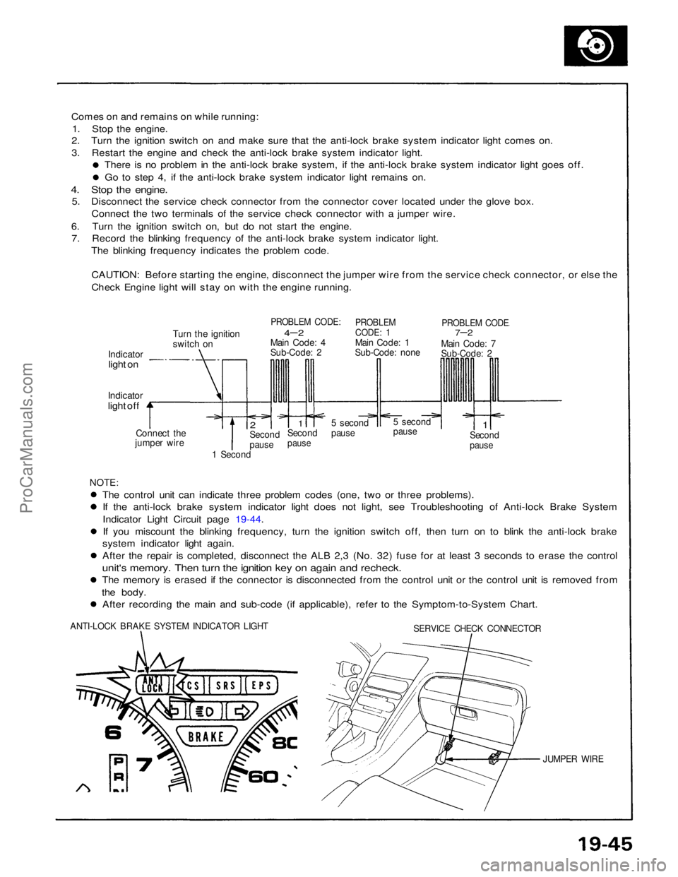
5. Disconnect the service check connector from the connector cover located under the glove box.
Connect the two terminals of the service check connector with a jumper wire.
6. Turn the ignition switch on, but do not start the engine. 7. Record the blinking frequency of the anti-lock brake system indicator light.
The blinking frequency indicates the problem code.
CAUTION: Before starting the engine, disconnect the jumper wire from the service check connector, or else the
Check Engine light will stay on with the engine running.
Turn the ignition
switch on
PROBLEM CODE:
4– 2
Main Code: 4
Sub-Code: 2
PROBLEM
CODE: 1
Main Code: 1
Sub-Code: none
PROBLEM CODE
7–2
Main Code: 7
Sub-Code: 2
Indicator
light on
Indicator
light off
Connect the
jumper wire
2
Second
pause
1
Second
pause
5 second
pause
5 second
pause
1
Second
pause
1 Second
NOTE:
The control unit can indicate three problem codes (one, two or three problems). If the anti-lock brake system indicator light does not light, see Troubleshooting of Anti-lock Brake System
Indicator Light Circuit page 19-44.
If you miscount the blinking frequency, turn the ignition switch off, then turn on to blink the anti-lock brake
system indicator light again. After the repair is completed, disconnect the ALB 2,3 (No. 32) fuse for at least 3 seconds to erase the control
unit's memory. Then turn the ignition key on again and recheck.
The memory is erased if the connector is disconnected from the control unit or the control unit is removed from
the body. After recording the main and sub-code (if applicable), refer to the Symptom-to-System Chart.
ANTI-LOCK BRAKE SYSTEM INDICATOR LIGHT
SERVICE CHECK CONNECTOR
JUMPER WIREProCarManuals.com