Page 1574 of 1640

Modulator/Solenoid Unit
Solenoid Leak Test
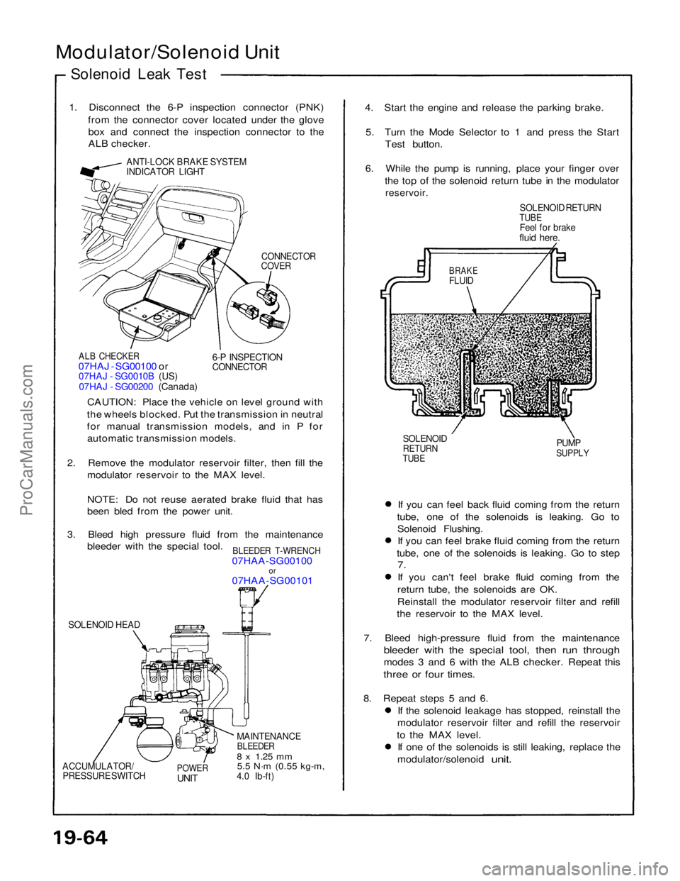
1. Disconnect the 6-P inspection connector (PNK) from the connector cover located under the glovebox and connect the inspection connector to the
ALB checker.
ANTI-LOCK BRAKE SYSTEM
INDICATOR LIGHT
CONNECTOR
COVER
ALB CHECKER
07HAJ - SG00100 or
07HAJ - SG0010B (US)
07HAJ - SG00200 (Canada)
6-P INSPECTION
CONNECTOR
CAUTION: Place the vehicle on level ground with
the wheels blocked. Put the transmission in neutral
for manual transmission models, and in P for automatic transmission models.
2. Remove the modulator reservoir filter, then fill the modulator reservoir to the MAX level.
NOTE: Do not reuse aerated brake fluid that has
been bled from the power unit.
3. Bleed high pressure fluid from the maintenance bleeder with the special tool.
BLEEDER T-WRENCH
07HAA-SG00100
or
07HAA-SG00101
SOLENOID HEAD
MAINTENANCE
BLEEDER
8 x
1.25
mm
5.5 N·m
(0.55 kg-m,
4.0 Ib-ft)
POWER
UNIT
ACCUMULATOR/
PRESSURE SWITCH
If you can feel back fluid coming from the return
tube, one of the solenoids is leaking. Go to Solenoid Flushing.If you can feel brake fluid coming from the return
tube, one of the solenoids is leaking. Go to step
7.
If you can't feel brake fluid coming from the return tube, the solenoids are OK.
Reinstall the modulator reservoir filter and refill
the reservoir to the MAX level.
7. Bleed high-pressure fluid from the maintenance
bleeder with the special tool, then run through
modes 3 and 6 with the ALB checker. Repeat this
three or four times.
8. Repeat steps 5 and 6. If the solenoid leakage has stopped, reinstall the
modulator reservoir filter and refill the reservoir
to the MAX level. If one of the solenoids is still leaking, replace the
modulator/solenoid
unit.
SOLENOID
RETURN
TUBE
PUMP
SUPPLY
BRAKE
FLUID
SOLENOID RETURN
TUBE
Feel for brake
fluid here.
4. Start the engine and release the parking brake.
5. Turn the Mode Selector to 1 and press the Start Test button.
6. While the pump is running, place your finger over the top of the solenoid return tube in the modulator
reservoir.ProCarManuals.com
Page 1576 of 1640

Bleeding
Air Bleeding with ALB Checker
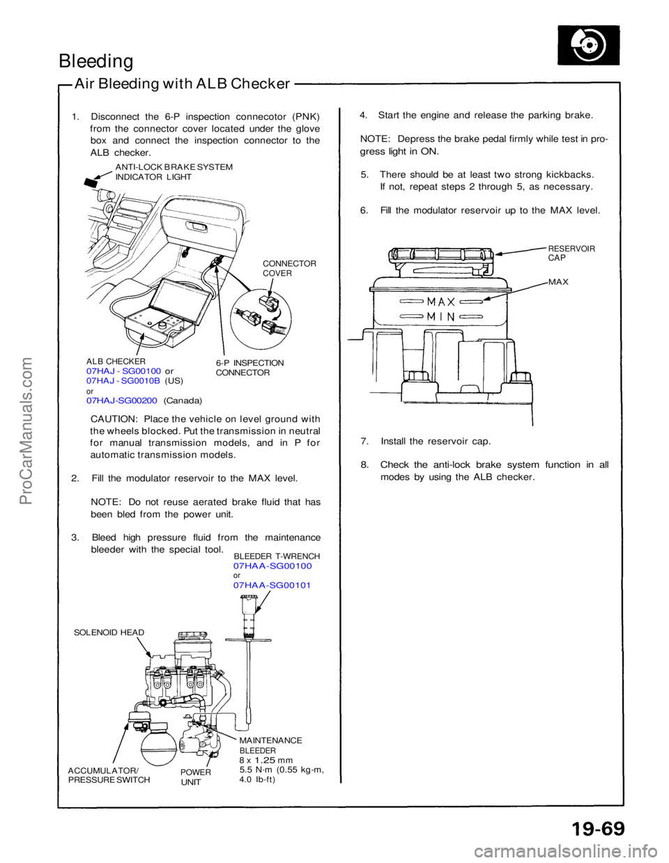
1. Disconnect the 6-P inspection connecotor (PNK) from the connector cover located under the glovebox and connect the inspection connector to the
ALB checker.
ANTI-LOCK BRAKE SYSTEM
INDICATOR LIGHT
CONNECTOR
COVER
ALB CHECKER
07HAJ - SG00100 or
07HAJ - SG0010B (US)
or
07HAJ-SG00200 (Canada)
6-P INSPECTION
CONNECTOR
CAUTION: Place the vehicle on level ground with
the wheels blocked. Put the transmission in neutral
for manual transmission models, and in P for automatic transmission models.
2. Fill the modulator reservoir to the MAX level.
NOTE: Do not reuse aerated brake fluid that has
been bled from the power unit.
3. Bleed high pressure fluid from the maintenance bleeder with the special tool.
BLEEDER T-WRENCH
07HAA-SG00100
or
07HAA-SG00101
SOLENOID HEAD
ACCUMULATOR/
PRESSURE SWITCH
POWER
UNIT
MAINTENANCE
BLEEDER
8 x
1.25
mm
5.5 N·m
(0.55 kg-m,
4.0 Ib-ft) 7. Install the reservoir cap.
8. Check the anti-lock brake system function in all
modes by using the ALB checker.
MAX
RESERVOIR
CAP
4. Start the engine and release the parking brake.
NOTE: Depress the brake pedal firmly while test in pro-
gress light in ON.
5. There should be at least two strong kickbacks. If not, repeat steps 2 through 5, as necessary.
6. Fill the modulator reservoir up to the MAX level.ProCarManuals.com
Page 1585 of 1640

Supplemental Restraint System (SRS)
Self-diagnosis Function
The SRS unit includes a self-diagnosis function. If there
is a failure in the sensors, SRS unit, inflator, or their cir-
cuits, the SRS light in the instrument panel goes ON.
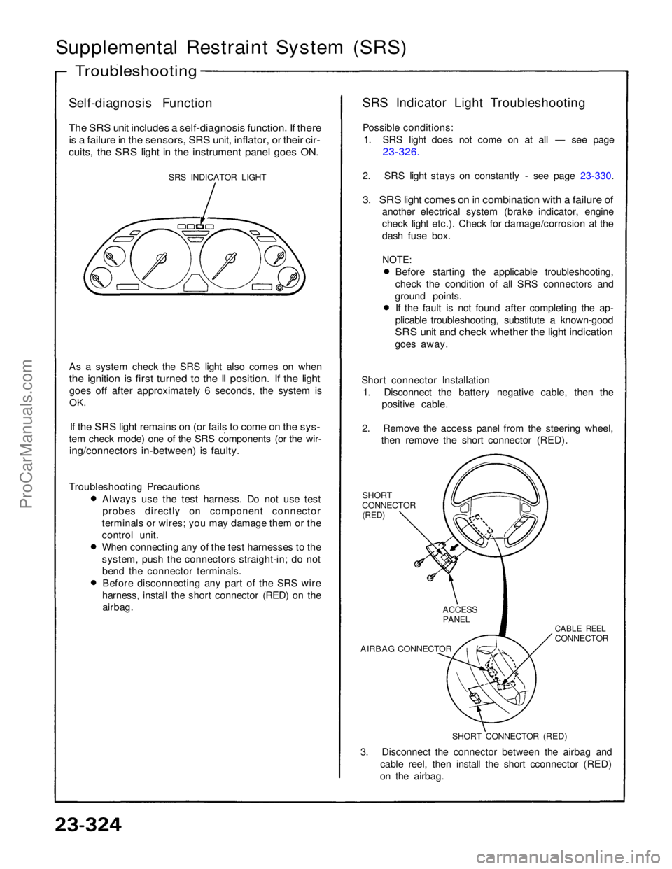
SRS INDICATOR LIGHT
As a system check the SRS light also comes on when
the ignition is first turned to the II position. If the light
goes off after approximately 6 seconds, the system is
OK.
If the SRS light remains on (or fails to come on the sys-
tem check mode) one of the SRS components (or the wir-
ing/connectors in-between) is faulty.
Troubleshooting Precautions Always use the test harness. Do not use test
probes directly on component connector
terminals or wires; you may damage them or the
control unit. When connecting any of the test harnesses to the
system, push the connectors straight-in; do not
bend the connector terminals. Before disconnecting any part of the SRS wire
harness, install the short connector (RED) on the airbag. SRS Indicator Light Troubleshooting
Possible conditions: 1. SRS light does not come on at all — see page
23-326.
2. SRS light stays on constantly - see page 23-330.
3. SRS light comes on in combination with a failure of
another electrical system (brake indicator, engine
check light etc.). Check for damage/corrosion at the
dash fuse box.
NOTE:
Before starting the applicable troubleshooting,
check the condition of all SRS connectors and
ground points. If the fault is not found after completing the ap-
plicable troubleshooting, substitute a known-good
SRS unit and check whether the light indication
goes away.
Short connector Installation 1. Disconnect the battery negative cable, then the positive cable.
2. Remove the access panel from the steering wheel, then remove the short connector (RED).
SHORT
CONNECTOR
(RED)
3. Disconnect the connector between the airbag and cable reel, then install the short cconnector (RED)
on the airbag.
Troubleshooting
SHORT CONNECTOR (RED)
AIRBAG CONNECTOR
CABLE REEL
CONNECTOR
ACCESS
PANELProCarManuals.com