1991 ACURA NSX drain bolt
[x] Cancel search: drain boltPage 72 of 1640
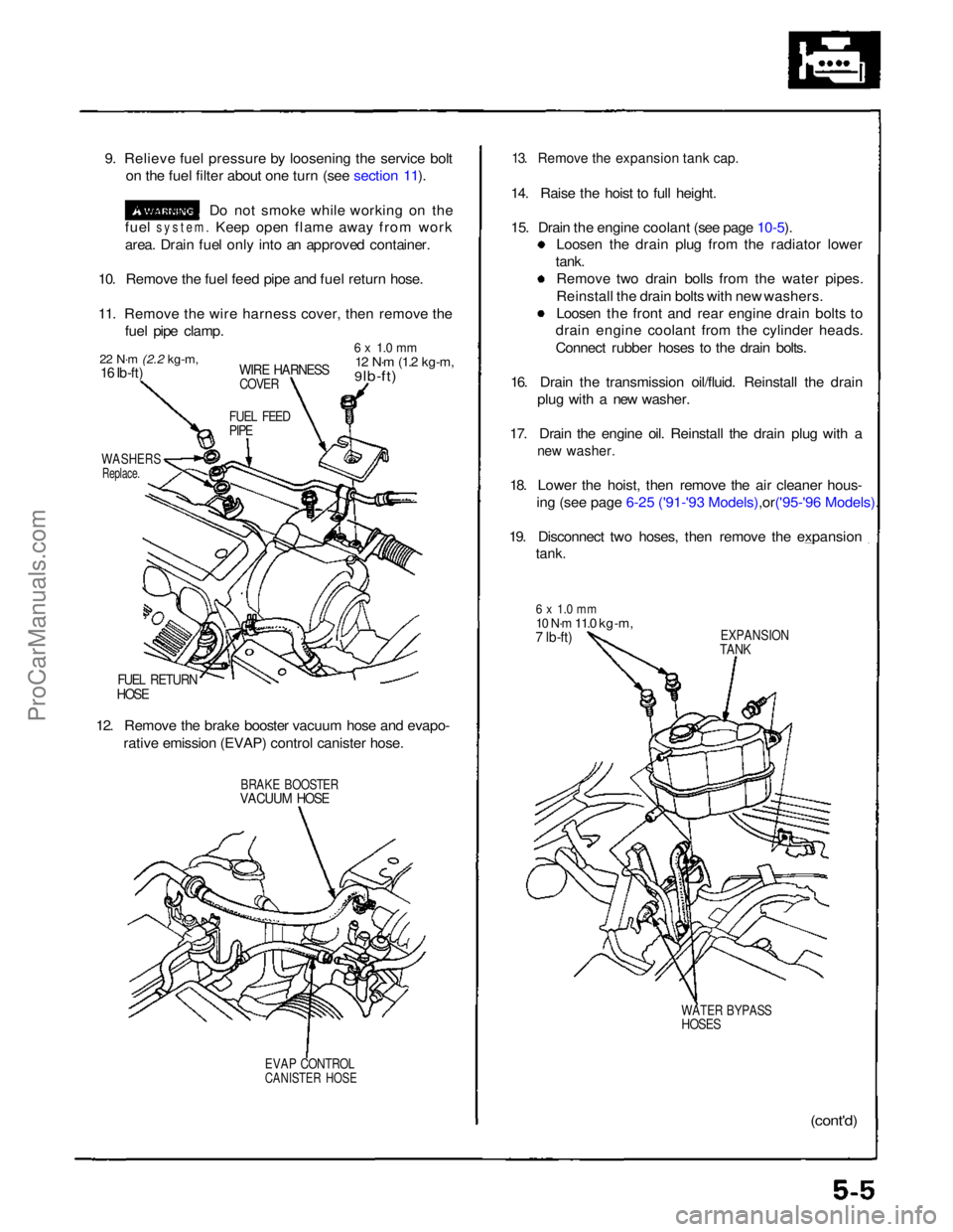
9. Relieve fuel pressure by loosening the service bolt
on the fuel filter about one turn (see section 11).
Do not smoke while working on the
fuel
system.
Keep open flame away from work
area. Drain fuel only into an approved container.
10. Remove the fuel feed pipe and fuel return hose.
11. Remove the wire harness cover, then remove the fuel pipe clamp.
22 N·m
(2.2 kg-m,
16 Ib-ft)
WIRE HARNESS
COVER
6 x 1.0 mm
12 N·m
(1.2 kg-m,
9 lb-ft)
FUEL FEED
PIPE
WASHERS
Replace.
FUEL RETURN
HOSE
12. Remove the brake booster vacuum hose and evapo- rative emission (EVAP) control canister hose.
BRAKE BOOSTER
VACUUM HOSE
EVAP CONTROL
CANISTER HOSE
13. Remove the expansion tank cap.
14. Raise the hoist to full height.
15. Drain the engine coolant (see page
10-5).
Loosen the drain plug from the radiator lower
tank. Remove two drain bolls from the water pipes.
Reinstall the drain bolts with new washers.
Loosen the front and rear engine drain bolts to
drain engine coolant from the cylinder heads.
Connect rubber hoses to the drain bolts.
16. Drain the transmission oil/fluid. Reinstall the drain plug with a new washer.
17. Drain the engine oil. Reinstall the drain plug with a
new washer.
18. Lower the hoist, then remove the air cleaner hous-
ing (see page 6-25 ('91-'93 Mode ls),or('95-'96 Models).
19. Disconnect two hoses, then remove the expansion
tank.
6 x 1.0 mm
10 N·m
11.0 kg-m,
7 lb-ft)
EXPANSION
TANK
WATER BYPASS
HOSES
(cont'd)ProCarManuals.com
Page 99 of 1640
Cylinder Heads
Removal
Engine removal is not required for this procedure. Make sure jacks and safety stands are
placed properly and hoist brackets ere attached to cor- rect positions on the engine.
CAUTION: Use a fender cover (special tool) to avoid damaging
painted surfaces. Unplug the wiring connectors carefully while holding
the connector portion to avoid damage.
To avoid damaging the cylinder heads, wait until the
engine coolant temperature drops below 100°F
(38°C) before loosening the retaining bolts. Do not open the engine cover when the roof panel is
stored (NSX-T open top).
NOTE:
Unspecified items are common.
Mark all wiring and hoses to avoid misconnection.
Also, be sure that they do not contact other wiring or
hoses or interfere with other parts.
Inspect the timing belt before removing the cylinder
head.
Turn the crankshaft pulley SO that the No. 1 piston is at top dead center (see page 6-19 ('91-'93) or ('94-'96)).
1. Disconnect the negative terminal from the battery.
2. Remove the expansion tank cap. Use care when removing the expan-
sion tank cap to avoid scalding by engine coolant
or steam.
3. Raise the car, then remove the right rear wheel/tire.
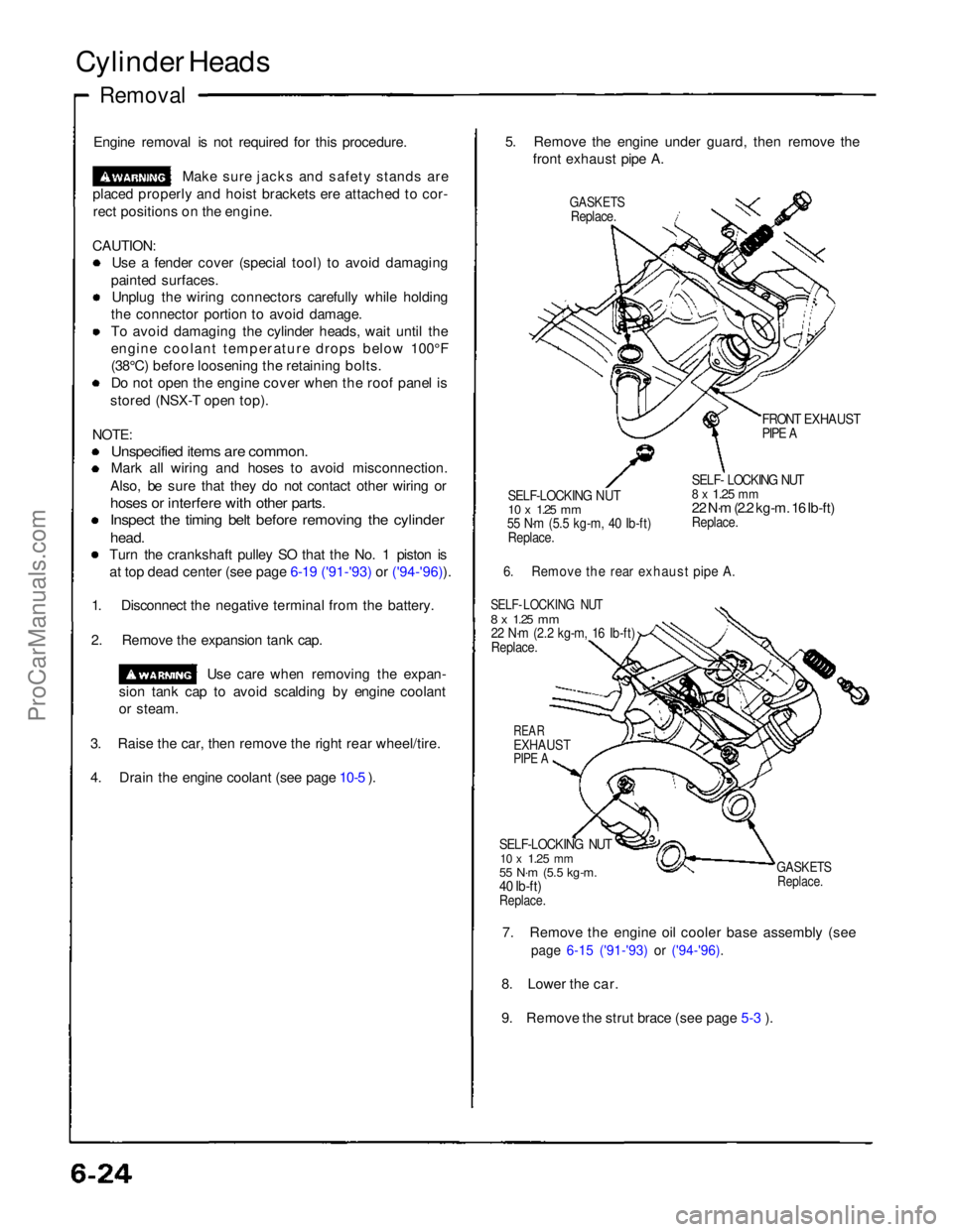
4. Drain the engine coolant (see page 10-5 ). 5. Remove the engine under guard, then remove the
front exhaust pipe A.
GASKETS
Replace.
FRONT EXHAUST
PIPE A
SELF-LOCKING NUT
10 x
1.25
mm
55 N·m (5.5 kg-m, 40 Ib-ft)
Replace.
SELF- LOCKING NUT
8 x
1.25
mm
22 N·m (2.2 kg-m. 16 Ib-ft)
Replace.
6. Remove the rear exhaust pipe A.
SELF- LOCKING NUT
8 x
1.25
mm
22 N·m (2.2 kg-m, 16 Ib-ft)
Replace.
REAR
EXHAUST
PIPE A
SELF-LOCKING NUT
10 x
1.25
mm
55 N·m (5.5 kg-m.
40 Ib-ft)
Replace.
GASKETS
Replace.
7. Remove the engine oil cooler base assembly (see
page 6-15 ('91-'93) or ('94-'96).
8. Lower the car.
9. Remove the strut brace (see page 5-3 ).ProCarManuals.com
Page 100 of 1640
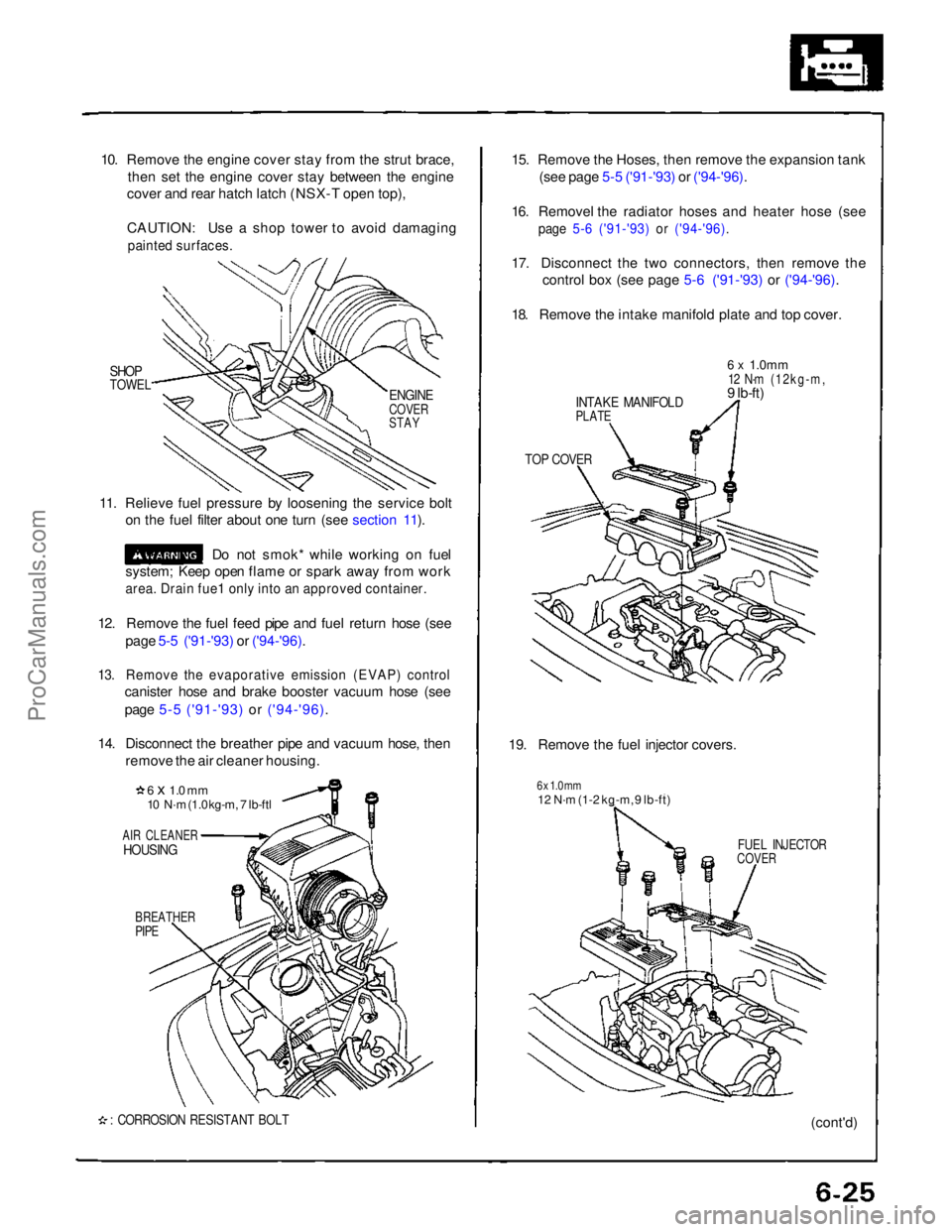
10. Remove the engine cover stay from the strut brace,
then set the engine cover stay between the engine
cover and rear hatch latch (NSX-T open top),
CAUTION: Use a shop tower to avoid damaging
painted surfaces.
SHOP
TOWEL
11. Relieve fuel pressure by loosening the service bolt on the fuel filter about one turn (see section 11).
Do not smok* while working on fuel
system; Keep open flame or spark away from work
area. Drain fue1 only into an approved container.
12. Remove the fuel feed pipe and fuel return hose (see page 5-5 ('91-'93) or ('94-'96).
13. Remove the evaporative emission (EVAP) control
canister hose and brake booster vacuum hose (see
page 5-5 ('91-'93) or ('94-'96).
14. Disconnect the breather pipe and vacuum hose, then remove the air cleaner housing.
6 x 1.0 mm
10 N·m (1.0 kg-m, 7 lb-ftl
AIR CLEANER
HOUSING
BREATHER
PIPE
: CORROSION RESISTANT BOLT
15. Remove the Hoses, then remove the expansion tank
(see page 5-5 ('91-'93) or ('94-'96).
16. Removel the radiator hoses and heater hose (see
page 5-6 ('91-'93) or ('94-'96).
17. Disconnect the two connectors, then remove the
control box (see page 5-6 ('91-'93) or ('94-'96).
18. Remove the intake manifold plate and top cover.
INTAKE MANIFOLD
PLATE
6 x
1.0mm
12 N·m (12kg-m,
9 lb-ft)
TOP COVER
19. Remove the fuel injector covers.
6 x 1.0 mm
12 N·m (1-2 kg-m, 9 lb-ft)
FUEL INJECTOR
COVER
(cont'd)
ENGINE
COVER
STAYProCarManuals.com
Page 153 of 1640
Oil Pump
Removal/lnspection/lnstallation
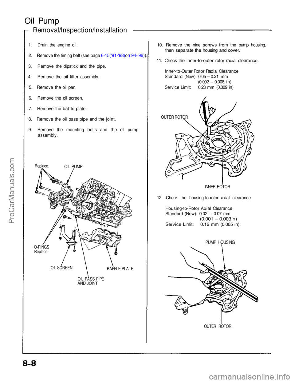
1. Drain the engine oil. 2. Remove the timing belt (see page 6-15('91-'93)or('94-'96)).
3. Remove the dipstick and the pipe.
4. Remove the oil filter assembly.
5. Remove the oil pan.
6. Remove the oil screen.
7. Remove the baffle plate,
8. Remove the oil pass
pipe and the joint.
9. Remove the mounting bolts and the oil pump
assembly.
Replace.
O-RINGS
Replace.
OIL SCREEN OIL PASS PIPE
AND JOINT
BAFFLE PLATE
OIL PUMP
10. Remove the nine screws from the pump housing,
then separate the housing and cover.
11. Check the inner-to-outer rotor radial clearance.
Inner-to-Outer Rotor Radial Clearance
Standard (New): 0.05 – 0.21 mm (0.002 – 0.008 in)
Service Limit: 0.23 mm (0.009 in)
OUTER ROTOR
INNER ROTOR
12. Check the housing-to-rotor axial clearance. Housing-to-Rotor Axial Clearance
Standard (New): 0.02 – 0.07 mm
(0.001 – 0.003 in)
Service Limit: 0.12 mm (0.005 in)
PUMP HOUSING
OUTER ROTORProCarManuals.com
Page 165 of 1640
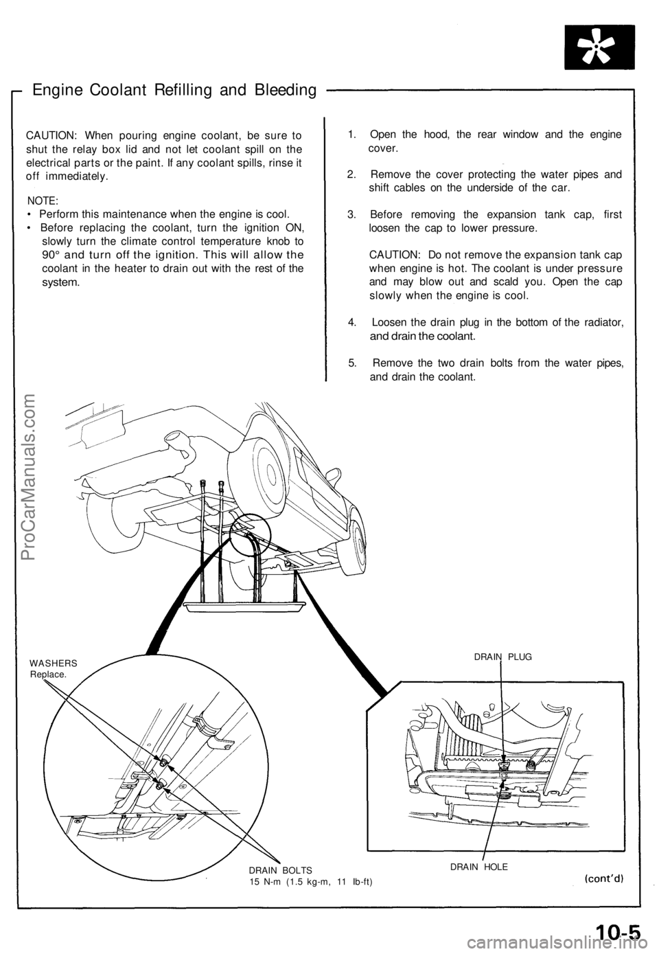
Engine Coolant Refilling and Bleeding
CAUTION: When pouring engine coolant, be sure to
shut the relay box lid and not let coolant spill on the
electrical parts or the paint. If any coolant spills, rinse it
off immediately.
NOTE:
• Perform this maintenance when the engine is cool.
• Before replacing the coolant, turn the ignition ON,
slowly turn the climate control temperature knob to
90° and turn off the ignition. This will allow the
coolant in the heater to drain out with the rest of the
system.
1. Open the hood, the rear window and the engine
cover.
2. Remove the cover protecting the water pipes and
shift cables on the underside of the car.
3. Before removing the expansion tank cap, first
loosen the cap to lower pressure.
CAUTION: Do not remove the expansion tank cap
when engine is hot. The coolant is under pressure
and may blow out and scald you. Open the cap
slowly when the engine is cool.
4. Loosen the drain plug in the bottom of the radiator,
and drain the coolant.
5. Remove the two drain bolts from the water pipes,
and drain the coolant.
WASHERS
Replace.
DRAIN BOLTS
15 N-m (1.5 kg-m, 11 Ib-ft)
DRAIN HOLE
DRAIN PLUGProCarManuals.com
Page 166 of 1640
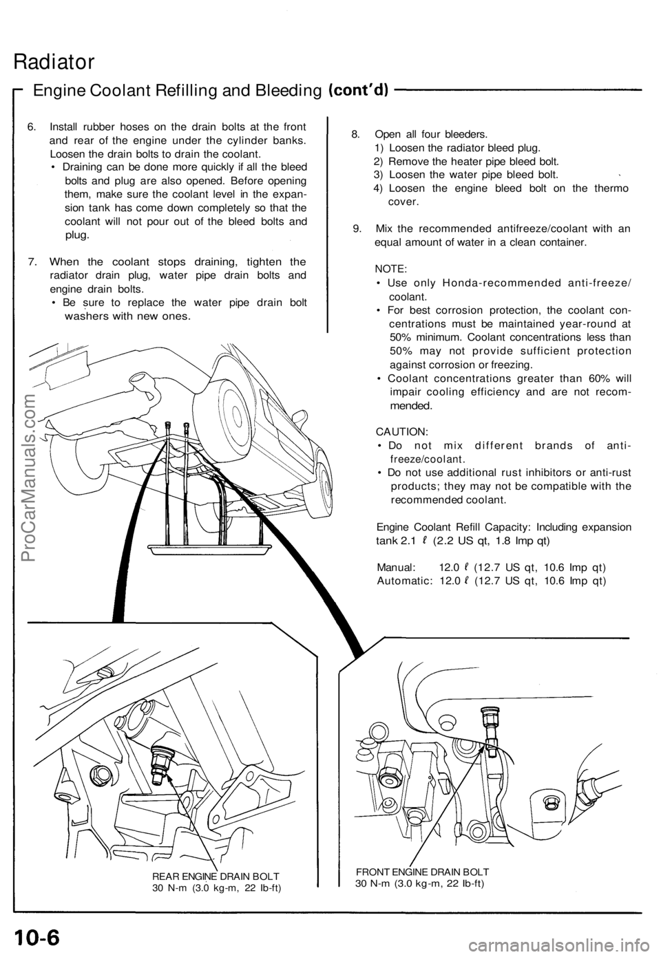
Radiator
Engine Coolan t Refillin g an d Bleedin g
6. Instal l rubbe r hose s o n th e drai n bolt s a t th e fron t
an d rea r of the engin e unde r th e cylinde r banks .
Loose n th e drai n bolt s t o drai n th e coolant .
• Drainin g ca n b e don e mor e quickl y i f al l th e blee d
bolt s an d plu g ar e als o opened . Befor e openin g
them , mak e sur e th e coolan t leve l i n th e expan -
sio n tan k ha s com e dow n completel y s o tha t th e
coolan t wil l no t pou r ou t o f th e blee d bolt s an d
plug .
7. Whe n th e coolan t stop s draining , tighte n th e
radiato r drai n plug , wate r pip e drai n bolt s an d
engin e drai n bolts .
• B e sur e t o replac e th e wate r pip e drai n bol t
washer s wit h ne w ones .
REAR ENGIN E DRAI N BOL T
3 0 N- m (3. 0 kg-m , 2 2 Ib-ft )
8. Ope n al l fou r bleeders .
1 ) Loose n th e radiato r blee d plug .
2 ) Remov e th e heate r pip e blee d bolt .
3 ) Loose n th e wate r pip e blee d bolt .
4 ) Loose n th e engin e blee d bol t o n th e therm o
cover.
9. Mi x th e recommende d antifreeze/coolan t wit h a n
equa l amoun t o f wate r i n a clea n container .
NOTE:
• Us e onl y Honda-recommende d anti-freeze /
coolant.
• Fo r bes t corrosio n protection , th e coolan t con -
centration s mus t b e maintaine d year-roun d a t
50 % minimum . Coolan t concentration s les s tha n
50 % ma y no t provid e sufficien t protectio n
agains t corrosio n o r freezing .
• Coolan t concentration s greate r tha n 60 % wil l
impai r coolin g efficienc y an d ar e no t recom -
mended.
CAUTION :
• D o no t mi x differen t brand s o f anti -
freeze/coolant .
• D o no t us e additiona l rus t inhibitor s o r anti-rus t
products ; the y ma y no t b e compatibl e wit h th e
recommende d coolant .
Engin e Coolan t Refil l Capacity : Includin g expansio n
tank 2. 1 (2. 2 U S qt , 1. 8 Im p qt )
Manual : 12. 0 (12. 7 U S qt , 10. 6 Im p qt )
Automatic : 12. 0 (12. 7 U S qt , 10. 6 Im p qt )
FRON T ENGIN E DRAI N BOL T30 N- m (3. 0 kg-m , 2 2 Ib-ft )
ProCarManuals.com
Page 170 of 1640
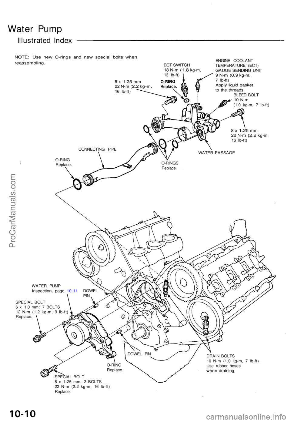
Water Pum p
Illustrate d Inde x
NOTE : Us e ne w O-ring s an d ne w specia l bolt s whe n
reassembling .
8 x 1.2 5 mm22 N- m (2. 2 kg- m16 Ib-ft )
ECT SWITC H18 N- m (1. 8 kg-m ,13 Ib-ft ) ENGIN
E COOLAN T
TEMPERATUR E (ECT )GAUG E SENDIN G UNI T9 N- m (0. 9 kg-m ,7 Ib-ft )Apply liqui d gaske tto th e threads .BLEED BOL T10 N- m(1.0 kg-m , 7 Ib-ft )
8 x 1.2 5 mm22 N- m (2. 2 kg-m ,16 Ib-ft )
O-RIN G
Replace .
DRAIN BOLT S
1 0 N- m (1. 0 kg-m , 7 Ib-ft )
Us e rubbe r hose s
when draining .
SPECIAL BOL T
8 x 1.2 5 mm : 2 BOLT S
2 2 N- m (2. 2 kg-m , 1 6 Ib-ft )
Replace . DOWE
L PI N
O-RIN G
Replace .
WATER PUM PInspection , pag e 10-1 1 DOWE LPIN
SPECIA L BOL T
6 x 1. 0 mm : 7 BOLT S
1 2 N- m (1. 2 kg-m , 9 Ib-ft )
Replace .
WATER PASSAG E
O-RING S
Replace .
CONNECTIN
G PIP E
ProCarManuals.com
Page 539 of 1640
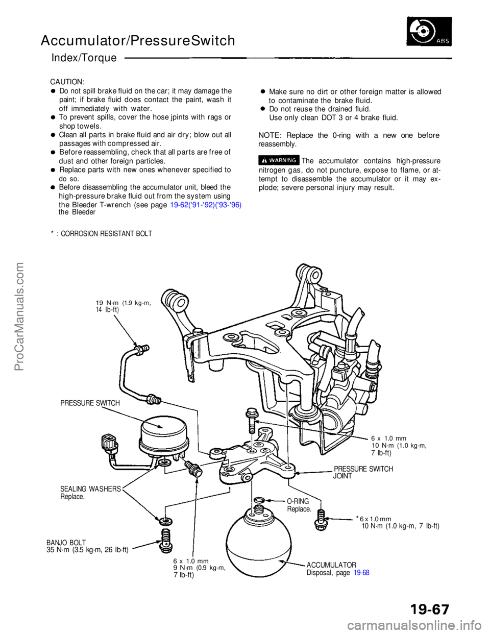
Accumulator/Pressure Switch
Index/Torque
CAUTION: Do not spill brake fluid on the car; it may damage the
paint; if brake fluid does contact the paint, wash it
off immediately with water.
To prevent spills, cover the hose jpints with rags or shop towels.
Clean all parts in brake fluid and air dry; blow out all passages with compressed air.
Before reassembling, check that all parts are free of
dust and other foreign particles. Replace parts with new ones whenever specified to
do so.
Before disassembling the accumulator unit, bleed the
high-pressure brake fluid out from the system using
the Bleeder T-wrench (see page 19-62('91-'92)('93-'96)
the Bleeder
*: CORROSION RESISTANT BOLT
Make sure no dirt or other foreign matter is allowed
to contaminate the brake fluid. Do not reuse the drained fluid.
Use only clean DOT 3 or 4 brake fluid.
NOTE: Replace the 0-ring with a new one before
reassembly. The accumulator contains high-pressure
nitrogen gas, do not puncture, expose to flame, or at-
tempt to disassemble the accumulator or it may ex-
plode; severe personal injury may result.
19 N·m
(1.9 kg-m,
14 Ib-ft)
PRESSURE SWITCH
SEALING WASHERS
Replace.
BANJO BOLT
35 N·m (3.5 kg-m, 26 Ib-ft)
6 x 1.0 mm
9 N·m
(0.9 kg-m,7 Ib-ft)
ACCUMULATOR
Disposal, page 19-68
* 6 x 1.0 mm
10 N·m (1.0 kg-m, 7 Ib-ft)
O-RING
Replace.
PRESSURE SWITCH
JOINT
6 x 1.0 mm
10 N·m
(1.0 kg-m,
7 Ib-ft)ProCarManuals.com