1991 ACURA NSX drain bolt
[x] Cancel search: drain boltPage 1148 of 1640
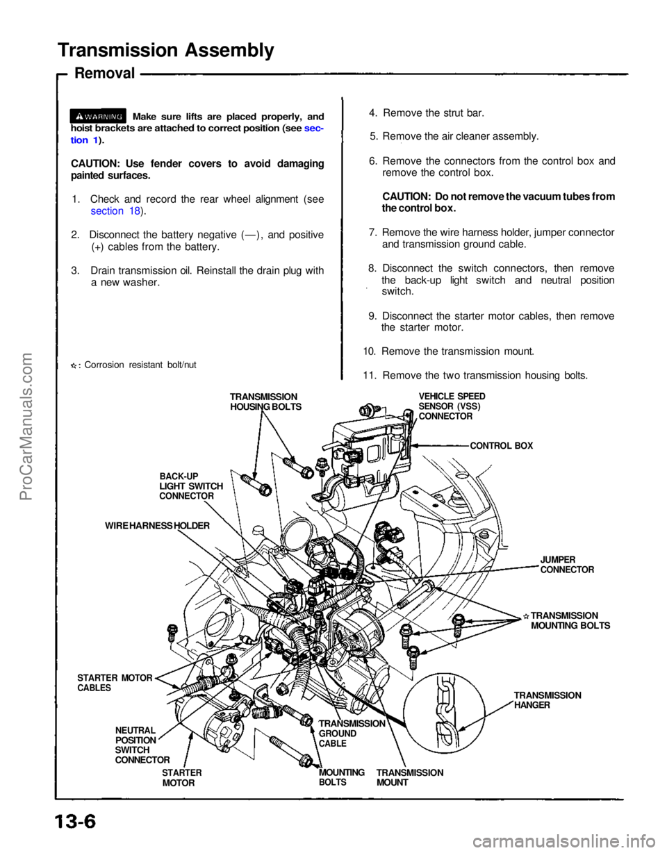
Transmission Assembly
Removal
CAUTION: Use fender covers to avoid damaging
painted surfaces.
1. Check and record the rear wheel alignment (see section 18).
2. Disconnect the battery negative (—), and positive (+) cables from the battery.
3. Drain transmission oil. Reinstall the drain plug with a new washer.
Corrosion resistant bolt/nut 4. Remove the strut bar.
5. Remove the air cleaner assembly.
6. Remove the connectors from the control box and remove the control box.
CAUTION: Do not remove the vacuum tubes from
the control box.
7. Remove the wire harness holder, jumper connector and transmission ground cable.
8. Disconnect the switch connectors, then remove the back-up light switch and neutral positionswitch.
9. Disconnect the starter motor cables, then remove the starter motor.
10. Remove the transmission mount.
11. Remove the two transmission housing bolts.
TRANSMISSION HOUSING BOLTS
BACK-UP
LIGHT SWITCH
CONNECTOR
WIRE HARNESS HOLDER
STARTER MOTOR
CABLES
NEUTRAL
POSITION
SWITCH
CONNECTOR
STARTER
MOTOR
TRANSMISSION
GROUND
CABLE
TRANSMISSION
MOUNT
MOUNTING
BOLTS
TRANSMISSION
HANGER
TRANSMISSION
MOUNTING BOLTS
JUMPER
CONNECTOR
VEHICLE SPEED
SENSOR (VSS)
CONNECTOR
CONTROL BOX
Make sure lifts are placed properly, and
hoist brackets are attached to correct position (see sec-
tion 1).ProCarManuals.com
Page 1153 of 1640
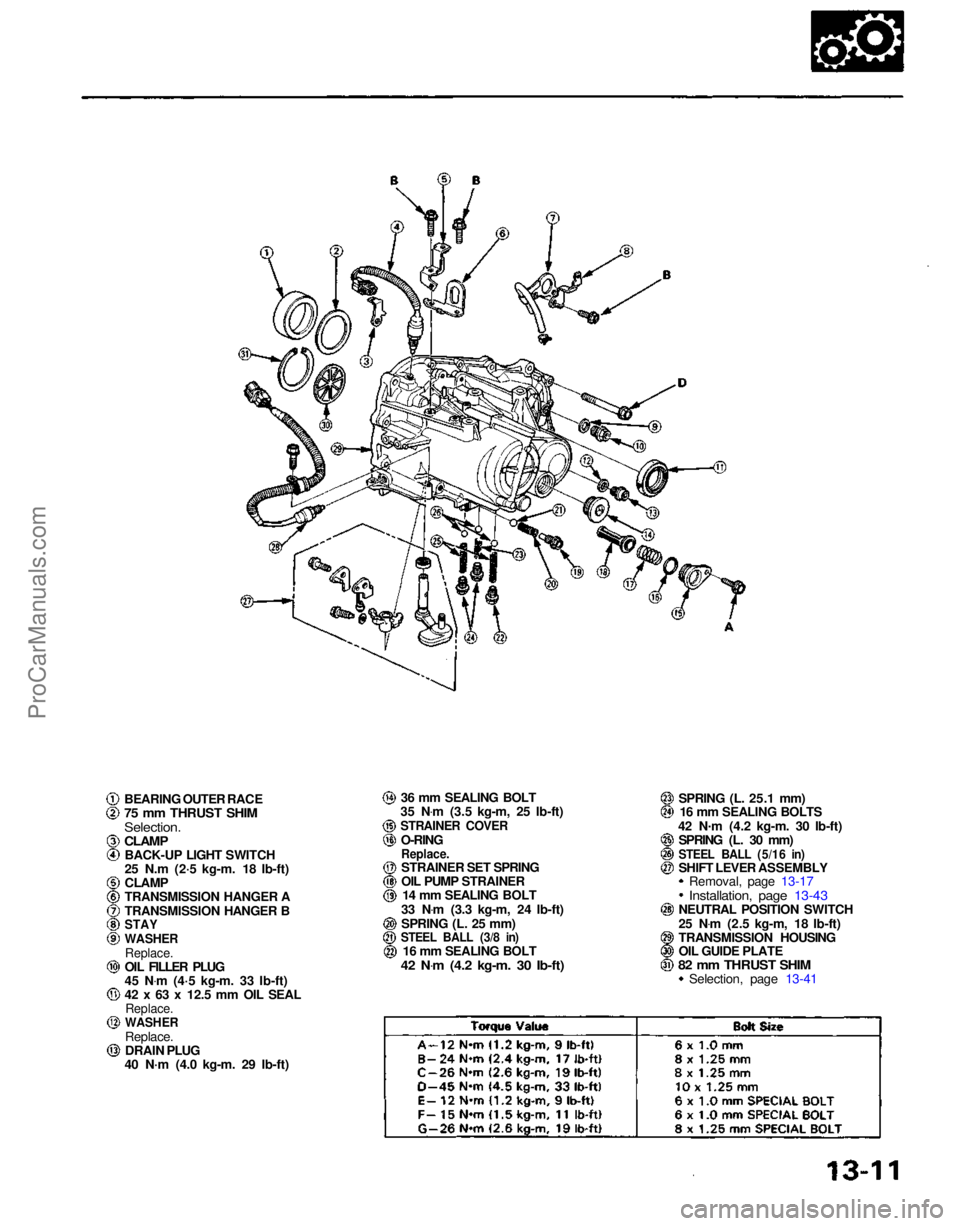
BEARING OUTER RACE
75 mm THRUST SHIM
Selection.
CLAMP
BACK-UP LIGHT SWITCH
25 N.m (2·5 kg-m. 18 Ib-ft)
CLAMP
TRANSMISSION HANGER A
TRANSMISSION HANGER B
STAY
WASHER
Replace.
OIL FILLER PLUG
45 N .
m (4·5 kg-m. 33 Ib-ft)
42 x 63 x 12.5 mm OIL SEAL
Replace.
WASHER
Replace.
DRAIN PLUG
40 N·m (4.0 kg-m. 29 Ib-ft) 36 mm SEALING BOLT
35 N .
m (3.5 kg-m, 25 Ib-ft)
STRAINER COVER
O-RING
Replace.
STRAINER SET SPRING
OIL PUMP STRAINER 14 mm SEALING BOLT
33 N .
m (3.3 kg-m, 24 Ib-ft)
SPRING (L. 25 mm)
STEEL BALL (3/8 in)
16 mm SEALING BOLT
42 N .
m (4.2 kg-m. 30 Ib-ft)
SPRING (L. 25.1 mm)
16 mm SEALING BOLTS
42 N .
m (4.2 kg-m. 30 Ib-ft)
SPRING (L. 30 mm)
STEEL BALL (5/16 in)
SHIFT LEVER ASSEMBLY Removal, page 13-17
Installation, page 13-43
NEUTRAL POSITION SWITCH
25 N .
m (2.5 kg-m, 18 Ib-ft)
TRANSMISSION HOUSING
OIL GUIDE PLATE
82 mm THRUST SHIM
Selection, page 13-41ProCarManuals.com
Page 1165 of 1640
Description
The automatic transmission is a combination of a 3-element torque converter and a triple-shaft electronically controlled
automatic transmission which provides 4 speeds forward and 1 in reverse. The entire unit is positioned in line with the
engine.
TORQUE CONVERTER, GEARS AND CLUTCHES
The torque converter consists of a pump, turbine and stator, assembled in a single unit.
They are connected to the engine crankshaft so they turn together as a unit as the engine turns.
Around the outside of the torque converter is a ring gear which meshes with the starter pinion when the engine is being
started. The entire torque converter assembly serves as a flywheel while transmitting power to the transmission mainshaft.
The transmission has three parallel shafts, the mainshaft, the countershaft, and the secondary shaft. The mainshaft is
in line with the engine crankshaft.
The mainshaft includes the clutches for 1st, and 4th, and gears for 3rd, 4th, Reverse and 1st (3rd gear is integral with
the mainshaft, while reverse gear is integral with 4th gear).
The countershaft includes the clutches for 1st-Hold and 3rd, and gears for 2nd, 3rd, 4th, Reverse and 1st.
The secondary shaft includes the 2nd clutch and gears for 2nd and 3rd.
The 4th and reverse gears can be locked to the countershaft at its center, providing 4th gear or Reverse, depending on
which way the selector is moved.
The gears on the mainshaft and secondary shaft are in constant mesh with those on the countershaft.
When certain combinations of gears in the transmission are engaged by clutches, power is transmitted from the main-
shaft to the countershaft to provide , , , and
ELECTRONIC CONTROL
The electronic control system consists of the Transmission Control Module (TCM), sensors, a linear solenoid and 4
solenoid valves. Shifting and lock-up are electronically controlled for comfortable driving under all conditions.
The TCM is located on the insulator center bulkhead, behind the driver's seat.
HYDRAULIC CONTROL
The valve bodies include the main valve body, secondary valve body, servo body, regulator valve body, throttle valve
body, lock-up valve body and the 2nd accumulator body.
They are bolted to the torque converter housing as an assembly.
The main valve body contains the manual valve, 1-2 shift valve, 2-3 shift valve, 3-4 shift valve, relief valve, one-way
relief valve and oil pump gears.
The secondary valve body contains the 3-2 kick-down valve, CPC (clutch pressure control) valve, 2nd orifice control
valve, 3rd orifice control valve, modulator valve, 4th exhaust valve, servo control valve, 2nd exhaust valve and 4-3 kick-
down valve.
The servo body contains the accumulator pistons and servo valve. The throttle valve body includes the throttle valve B
which is bolted onto the servo body.
The regulator valve body contains the pressure regulator valve, lock-up control valve and cooler relief valve. Fluid from
the regulator passes through the manual valve to the various control valves.
The lock-up valve body contains the lock-up timing B valve and lock-up shift valve. The 2nd accumulator body contains
the accumulator pistons and limited slip differential (LSD) relief valve.
The torque converter check valve is located in the torque converter housing, under the main valve body.
The 1st, 1st-hold, 3rd and 4th clutches receive oil from their respective feed pipes.
SHIFT CONTROL MECHANISM
Input from various sensors located throughout the car determines which shift control solenoid valve the TCM will ac-
tivate. Activating a shift control solenoid valve changes modulator pressure, causing a shift valve to move. This
pressurizes a line to one of the clutches, engaging that clutch and its corresponding gear.
LOCK-UP MECHANISM
In position and position in 2nd, 3rd and 4th, pressurized fluid is drained from the back of the torque converter
through an oil passage, causing the lock-up piston to be held, against the torque converter cover. As this takes place, the
mainshaft rotates at the same speed as the engine crankshaft. Together with hydraulic control, the TCM optimizes the
timing of the lock-up mechaism.
The lock-up valves control the range of lock-up according to lock-up control solenoid valves A and B, and throttle valve B.
When lock-up control solenoid valves A and B activate, modulator pressure changes. The lock-up control solenoid valves
A and B are mounted on the torque converter housing, and are controlled by the TCM.
(cont'd)ProCarManuals.com
Page 1229 of 1640
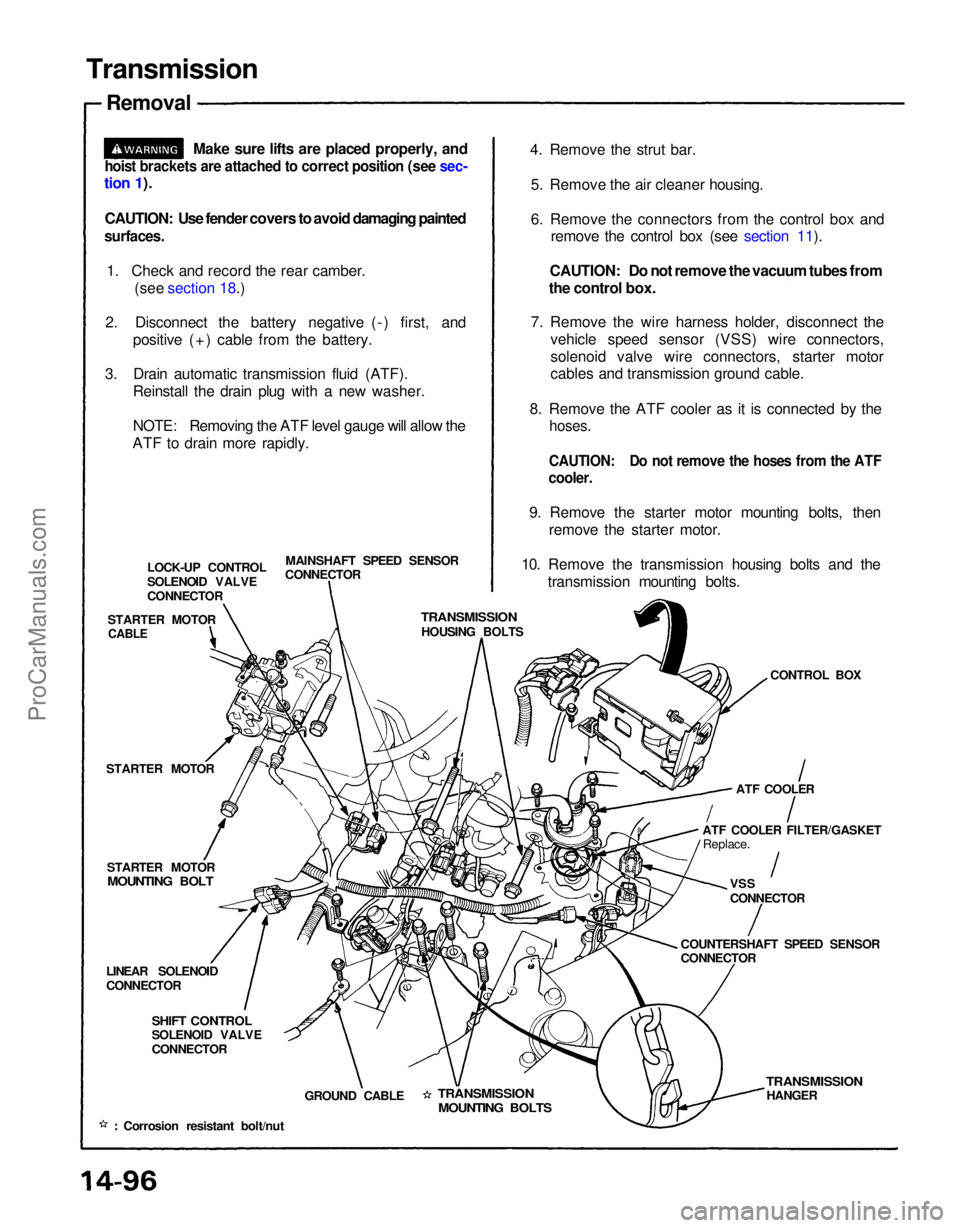
Transmission
Removal
Make sure lifts are placed properly, and
hoist brackets are attached to correct position (see sec-
tion 1).
CAUTION: Use fender covers to avoid damaging painted
surfaces.
1. Check and record the rear camber. (see section 18.)
2. Disconnect the battery negative (-) first, and positive (+) cable from the battery.
3. Drain automatic transmission fluid (ATF). Reinstall the drain plug with a new washer.
NOTE: Removing the ATF level gauge will allow the
ATF to drain more rapidly. 4. Remove the strut bar.
5. Remove the air cleaner housing.
6. Remove the connectors from the control box and remove the control box (see section 11).
CAUTION: Do not remove the vacuum tubes from
the control box.
7. Remove the wire harness holder, disconnect the vehicle speed sensor (VSS) wire connectors,
solenoid valve wire connectors, starter motor
cables and transmission ground cable.
8. Remove the ATF cooler as it is connected by the
hoses.
CAUTION: Do not remove the hoses from the ATF
cooler.
9. Remove the starter motor mounting bolts, then remove the starter motor.
10. Remove the transmission housing bolts and the transmission mounting bolts.
MAINSHAFT SPEED SENSOR
CONNECTOR
LOCK-UP CONTROL
SOLENOID VALVE
CONNECTOR
STARTER MOTOR
TRANSMISSION
HOUSING BOLTS
CONTROL BOX
STARTER MOTOR
STARTER MOTOR
MOUNTING BOLT
ATF COOLER
ATF COOLER FILTER/GASKET Replace.
VSS
CONNECTOR
COUNTERSHAFT SPEED SENSOR
CONNECTOR
LINEAR SOLENOID
CONNECTOR
SHIFT CONTROL
SOLENOID VALVE
CONNECTOR
GROUND CABLE
TRANSMISSION
MOUNTING BOLTS
TRANSMISSION
HANGER
Corrosion resistant bolt/nut
CABLEProCarManuals.com
Page 1515 of 1640
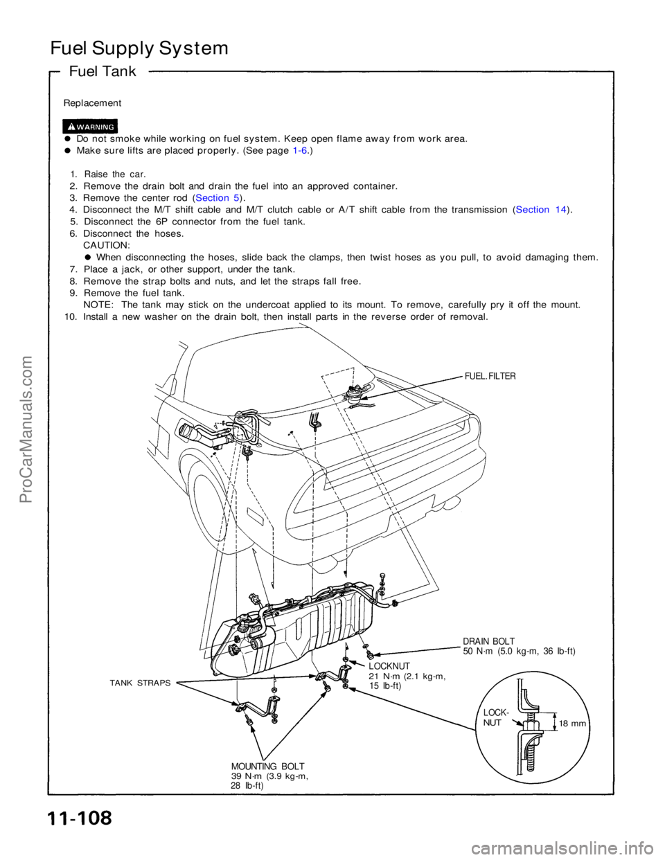
Fuel Supply System
Fuel Tank
Replacement
Do not smoke while working on fuel system. Keep open flame away from work area.Make sure lifts are placed properly. (See page 1-6.)
1. Raise the car.
2. Remove the drain bolt and drain the fuel into an approved container.
3. Remove the center rod (Section 5).
4. Disconnect the M/T shift cable and M/T clutch cable or A/T shift cable from the transmission (Section 14).
5. Disconnect the 6P connector from the fuel tank.
6. Disconnect the hoses. CAUTION: When disconnecting the hoses, slide back the clamps, then twist hoses as you pull, to avoid damaging them.
7. Place a jack, or other support, under the tank.
8. Remove the strap bolts and nuts, and let the straps fall free.
9. Remove the fuel tank. NOTE: The tank may stick on the undercoat applied to its mount. To remove, carefully pry it off the mount.
10. Install a new washer on the drain bolt, then install parts in the reverse order of removal.
FUEL. FILTER
DRAIN BOLT
50 N·m (5.0 kg-m, 36 Ib-ft)
LOCKNUT
21 N·m
(2.1 kg-m,
15 Ib-ft)
TANK STRAPS
LOCK-
NUT
18 mm
MOUNTING BOLT
39 N·m
(3.9 kg-m,
28 Ib-ft)ProCarManuals.com
Page 1539 of 1640
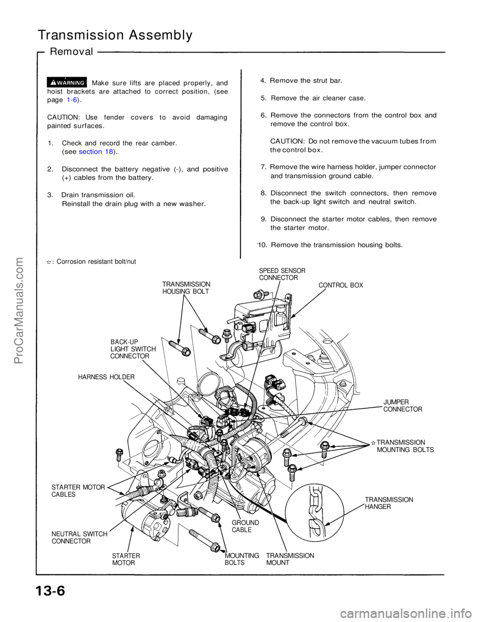
Transmission Assembly
Removal
Make sure lifts are placed properly, and
hoist brackets are attached to correct position, (see
page 1-6).
CAUTION: Use fender covers to avoid damaging
painted surfaces.
1. Check and record the rear camber.
(see section 18).
2. Disconnect the battery negative (-), and positive (+) cables from the battery.
3. Drain transmission oil. Reinstall the drain plug with a new washer.
Corrosion resistant bolt/nut
TRANSMISSION
HOUSING BOLT
BACK-UP
LIGHT SWITCH
CONNECTOR
HARNESS HOLDER
STARTER MOTOR
CABLES
NEUTRAL SWITCH
CONNECTOR
STARTER
MOTOR
MOUNTING
BOLTS
TRANSMISSION
MOUNT
GROUND
CABLE
TRANSMISSION
HANGER
TRANSMISSION
MOUNTING BOLTS
JUMPER
CONNECTOR
CONTROL BOX
SPEED SENSOR
CONNECTOR
4. Remove the strut bar.
5. Remove the air cleaner case.
6. Remove the connectors from the control box and remove the control box.
CAUTION: Do not remove the vacuum tubes from
the control box.
7. Remove the wire harness holder, jumper connector and transmission ground cable.
8. Disconnect the switch connectors, then remove the back-up light switch and neutral switch.
9. Disconnect the starter motor cables, then remove the starter motor.
10. Remove the transmission housing bolts.ProCarManuals.com
Page 1544 of 1640
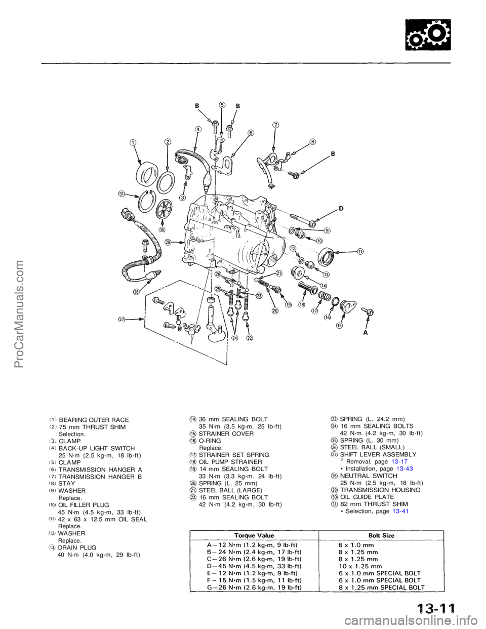
BEARING OUTER RACE
75 mm THRUST SHIM
Selection.
CLAMP
BACK-UP LIGHT SWITCH
25 N·m (2.5 kg-m, 18 Ib-ft)
CLAMP
TRANSMISSION HANGER A
TRANSMISSION HANGER B
STAY
WASHER
Replace.
OIL FILLER PLUG
45 N·m (4.5 kg-m, 33 Ib-ft)
42 x 63 x 12.5 mm OIL SEAL
Replace.
WASHER
Replace.
DRAIN PLUG
40 N·m (4.0 kg-m, 29 Ib-ft) 36 mm SEALING BOLT
35 N·m (3.5 kg-m. 25 Ib-ft)
STRAINER COVER O-RING
Replace.
STRAINER SET SPRING
OIL PUMP STRAINER
14 mm SEALING BOLT
33 N·m (3.3 kg-m. 24 Ib-ft)
SPRING (L. 25 mm)
STEEL BALL (LARGE) 16 mm SEALING BOLT
42 N·m (4.2 kg-m, 30 Ib-ft) SPRING (L. 24.2 mm)
16 mm SEALING BOLTS
42 N·m (4.2 kg-m, 30 Ib-ft)
SPRING (L. 30 mm)
STEEL BALL (SMALL)
SHIFT LEVER ASSEMBLY
0 Removal, page
13-17
• Installation, page 13-43
NEUTRAL SWITCH
25 N·m (2.5 kg-m, 18 Ib-ft)
TRANSMISSION HOUSING
OIL GUIDE PLATE
82 mm THRUST SHIM
• Selection, page
13-41
ProCarManuals.com